User Guide
Page 4
Contents 2.5.8 PIKE slot (Z8NA-D6 model only 2-20 2.5.9 Installing an ASUS PIKE RAID card (Z8NA-D6 model only 2-21 2.5.10 Installing i Button (Z8NA-D6 model only 2-22 2.5.11 Installing ASMB4 management board (Z8NA-D6 model only 2-22 2.5.12 Installing the audio card 2-23 2.5.13 Connect Thermal sensor cable 2-23 2.6 Jumpers 2-24 2.7 Connectors 2-29 2.7.1 Rear panel connectors 2-29 2.7.2 Internal connectors 2-30 Chapter...
Contents 2.5.8 PIKE slot (Z8NA-D6 model only 2-20 2.5.9 Installing an ASUS PIKE RAID card (Z8NA-D6 model only 2-21 2.5.10 Installing i Button (Z8NA-D6 model only 2-22 2.5.11 Installing ASMB4 management board (Z8NA-D6 model only 2-22 2.5.12 Installing the audio card 2-23 2.5.13 Connect Thermal sensor cable 2-23 2.6 Jumpers 2-24 2.7 Connectors 2-29 2.7.1 Rear panel connectors 2-29 2.7.2 Internal connectors 2-30 Chapter...
User Guide
Page 28
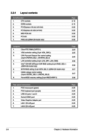
...BIOS recovery setting (3-pin RECOVERY1) Page 2-24 2-25 2-25 2-26 2-26 2-27 2-27 2-28 Rear panel connectors 1. PCI Express x8 slots (x4 link) 5. iBTN RAID setting (3-pin IBTN_SEL1) (Z8NA-D6 model only) 7. PS/2 mouse port (green) 2. Serial (COM1) port 5. Clear RTC RAM (CLRTC1)...1 (RJ-45) port 7. PCI Express x16 slot (x16 link) 4. VGA controller setting (3-pin VGA_SW1)) 3. Video Graphics Adapter port 6. PIKE slot (Z8NA-D6 model only) Page 2-10 2-15 2-20 2-20 2-20 2-20 2-20 Jumpers 1. LVDDR3_SEL2) 8. PCI slot 7. CPU sockets 2. MIO PCIE slot 6....
...BIOS recovery setting (3-pin RECOVERY1) Page 2-24 2-25 2-25 2-26 2-26 2-27 2-27 2-28 Rear panel connectors 1. PCI Express x8 slots (x4 link) 5. iBTN RAID setting (3-pin IBTN_SEL1) (Z8NA-D6 model only) 7. PS/2 mouse port (green) 2. Serial (COM1) port 5. Clear RTC RAM (CLRTC1)...1 (RJ-45) port 7. PCI Express x16 slot (x16 link) 4. VGA controller setting (3-pin VGA_SW1)) 3. Video Graphics Adapter port 6. PIKE slot (Z8NA-D6 model only) Page 2-10 2-15 2-20 2-20 2-20 2-20 2-20 Jumpers 1. LVDDR3_SEL2) 8. PCI slot 7. CPU sockets 2. MIO PCIE slot 6....

User Guide
Page 49
... table below for the LAN port LED indications. 7. This port is for a PS/2 mouse. 2. Refer to a Local Area Network (LAN) through a network hub. 2.7 Connectors 2.7.1 Rear panel connectors 1. Refer to a Local Area Network (LAN) through a network hub. These two 4-pin Universal Serial Bus (USB) ports are available for the LAN port LED... BLINKING Data activity Speed LED Status Description OFF 10 Mbps connection ORANGE 100 Mbps connection GREEN 1 Gbps connection ACT/LINK SPEED LED LED LAN port ASUS Z8NA-D6 Series 2-29
... table below for the LAN port LED indications. 7. This port is for a PS/2 mouse. 2. Refer to a Local Area Network (LAN) through a network hub. 2.7 Connectors 2.7.1 Rear panel connectors 1. Refer to a Local Area Network (LAN) through a network hub. These two 4-pin Universal Serial Bus (USB) ports are available for the LAN port LED... BLINKING Data activity Speed LED Status Description OFF 10 Mbps connection ORANGE 100 Mbps connection GREEN 1 Gbps connection ACT/LINK SPEED LED LED LAN port ASUS Z8NA-D6 Series 2-29

User Guide
Page 50
The read or write activities of any device connected to the SATA or SAS add-on card causes the front panel LED to light up to the SATA or SAS add-on the speed of data transfer rate. Hard disk activity LED connector (4-pin HDLED1) This ...
The read or write activities of any device connected to the SATA or SAS add-on card causes the front panel LED to light up to the SATA or SAS add-on the speed of data transfer rate. Hard disk activity LED connector (4-pin HDLED1) This ...

User Guide
Page 57
...the HDD Activity LED cable to hear system beeps and warnings. 4. ASUS Z8NA-D6 Series 2-37 System power LED (3-pin PLED) This 3-pin connector ...the power switch for more than four seconds while the system is for the system power button. 13. System panel connector (20-pin PANEL1) This connector supports several chassis-mounted functions. 1. Message LED (2-pin MLED) This ...(4-pin SPEAKER) This 4-pin connector is for the message LED cable that connects to the HDD. 5. ATX power button/soft-off button (2-pin PWRSW) This connector is for system reboot without turning off mode depending...
...the HDD Activity LED cable to hear system beeps and warnings. 4. ASUS Z8NA-D6 Series 2-37 System power LED (3-pin PLED) This 3-pin connector ...the power switch for more than four seconds while the system is for the system power button. 13. System panel connector (20-pin PANEL1) This connector supports several chassis-mounted functions. 1. Message LED (2-pin MLED) This ...(4-pin SPEAKER) This 4-pin connector is for the message LED cable that connects to the HDD. 5. ATX power button/soft-off button (2-pin PWRSW) This connector is for system reboot without turning off mode depending...

User Guide
Page 58
...locator. 2-38 Chapter 2: Hardware information LAN activity LED (2-pin LAN1_LED, LAN2_LED) These leads are for the locator button on the front panel. The LEDs will light up when the Locator button is short CASEOPEN and GND pin by jumper cap to these 2-pin connector. ... feature for Gigabit LAN activity LEDs on the front panel. 14. Chassis intrusion (4-1 pin CHASSIS) These leads are for additional front panel features including front panel SMB, locator LED and switch, chassis intrusion, and LAN LEDs. 1. Auxiliary panel connector (20-pin AUX_PANEL1) This connector is for ...
...locator. 2-38 Chapter 2: Hardware information LAN activity LED (2-pin LAN1_LED, LAN2_LED) These leads are for the locator button on the front panel. The LEDs will light up when the Locator button is short CASEOPEN and GND pin by jumper cap to these 2-pin connector. ... feature for Gigabit LAN activity LEDs on the front panel. 14. Chassis intrusion (4-1 pin CHASSIS) These leads are for additional front panel features including front panel SMB, locator LED and switch, chassis intrusion, and LAN LEDs. 1. Auxiliary panel connector (20-pin AUX_PANEL1) This connector is for ...

User Guide
Page 61
...that all the connections, replace the system case cover. 2. Turn on the system front panel case lights up or switch between orange and green after the system LED turns on ...in Chapter 4. Check the jumper settings and connections or call your monitor complies with a surge protector. 5. ASUS Z8NA-D6 Series 3-3 Monitor b. The system then runs the power-on , hold down the key to the power...off. 3. If you do not see anything within 30 seconds from the time you press the ATX power button. After making all switches are running, the BIOS beeps or additional messages appear on ...
...that all the connections, replace the system case cover. 2. Turn on the system front panel case lights up or switch between orange and green after the system LED turns on ...in Chapter 4. Check the jumper settings and connections or call your monitor complies with a surge protector. 5. ASUS Z8NA-D6 Series 3-3 Monitor b. The system then runs the power-on , hold down the key to the power...off. 3. If you do not see anything within 30 seconds from the time you press the ATX power button. After making all switches are running, the BIOS beeps or additional messages appear on ...


