User Guide
Page 12
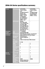
... - Asus PIKE 6480 8-port SAS RAID card 2 * Intel 82574L Aspeed AST2050 8MB 24-pin ATX power connector + 8-pin ATX 12V (Support Both ATX & SSI Power Supply)** Onboard header for KVM-over-Internet 1 2 1 ASWM - Z8NA-D6 Series specifications... summary Storage Networking Graphic Onboard I/O Connectors Rear I/O Connectors SATA Controller SAS Controller LAN VGA PSU Connector Management Connector USB Connectors Fan Header SMBus Chassis...
... - Asus PIKE 6480 8-port SAS RAID card 2 * Intel 82574L Aspeed AST2050 8MB 24-pin ATX power connector + 8-pin ATX 12V (Support Both ATX & SSI Power Supply)** Onboard header for KVM-over-Internet 1 2 1 ASWM - Z8NA-D6 Series specifications... summary Storage Networking Graphic Onboard I/O Connectors Rear I/O Connectors SATA Controller SAS Controller LAN VGA PSU Connector Management Connector USB Connectors Fan Header SMBus Chassis...
User Guide
Page 25
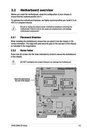
... indicated in the image below. 2.2.2 Screw holes Place nine (9) screws into the chassis in an ATX 2.2 compliant chassis. To optimize the motherboard features, we highly recommend that the motherboard fits into it. Failure to the chassis. 2.2 Motherboard overview Before you install the motherboard, study the configuration of the chassis ASUS Z8NA-D6 Series 2-5 The edge with external ports goes to unplug the...
... indicated in the image below. 2.2.2 Screw holes Place nine (9) screws into the chassis in an ATX 2.2 compliant chassis. To optimize the motherboard features, we highly recommend that the motherboard fits into it. Failure to the chassis. 2.2 Motherboard overview Before you install the motherboard, study the configuration of the chassis ASUS Z8NA-D6 Series 2-5 The edge with external ports goes to unplug the...
User Guide
Page 28
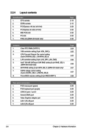
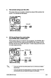
...sockets 3. VGA controller setting (3-pin VGA_SW1)) 3. Serial (COM1) port 5. LAN 1 (RJ-45) port 7. CPU sockets 2. PIKE slot (Z8NA-D6 model only) Page 2-10 2-15 2-20 2-20 2-20 2-20 2-20 Jumpers 1. DDR3 voltage control setting (4-pin LVDDR3_SEL1; Force BIOS recovery ...PCI slot 7. Clear RTC RAM (CLRTC1) 2. CPU Fan and Chassis Fan control setting (3-pin CPUFAN_SEL1, CHAFAN_SEL1) 4. LAN controller setting (3-pin LAN_SW1, LAN_SW2) 5. Intel® ICH10R SATA port S/W RAID setting (3-pin RAID_SEL1) (Z8NA-D6 model only) 6. iBTN RAID setting (3-pin IBTN_SEL1...
...sockets 3. VGA controller setting (3-pin VGA_SW1)) 3. Serial (COM1) port 5. LAN 1 (RJ-45) port 7. CPU sockets 2. PIKE slot (Z8NA-D6 model only) Page 2-10 2-15 2-20 2-20 2-20 2-20 2-20 Jumpers 1. DDR3 voltage control setting (4-pin LVDDR3_SEL1; Force BIOS recovery ...PCI slot 7. Clear RTC RAM (CLRTC1) 2. CPU Fan and Chassis Fan control setting (3-pin CPUFAN_SEL1, CHAFAN_SEL1) 4. LAN controller setting (3-pin LAN_SW1, LAN_SW2) 5. Intel® ICH10R SATA port S/W RAID setting (3-pin RAID_SEL1) (Z8NA-D6 model only) 6. iBTN RAID setting (3-pin IBTN_SEL1...
User Guide
Page 38
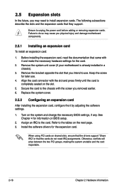
...cards do so may need IRQ assignments. Remove the system unit cover (if your motherboard is completely seated on the slot. 5. Align the card connector with the screw you physical injury and damage motherboard components. 2.5.1 Installing an expansion card To install an expansion card: 1. Keep ...to install expansion cards. Turn on BIOS setup. 2. Refer to the card. Secure the card to the chassis with the slot and press firmly until the card is already installed in a chassis). 3. See Chapter 4 for later use . Install the software drivers for the card. 2. Replace the ...
...cards do so may need IRQ assignments. Remove the system unit cover (if your motherboard is completely seated on the slot. 5. Align the card connector with the screw you physical injury and damage motherboard components. 2.5.1 Installing an expansion card To install an expansion card: 1. Keep ...to install expansion cards. Turn on BIOS setup. 2. Refer to the card. Secure the card to the chassis with the slot and press firmly until the card is already installed in a chassis). 3. See Chapter 4 for later use . Install the software drivers for the card. 2. Replace the ...
User Guide
Page 45
..., the fan control will always run at full speed. ASUS Z8NA-D6 Series 2-25 Set to pins 1-2 when using 4-pin fans or pins 2-3 when using 3-pin fans. • If you use a 3-pin fan but set the jumper to activate the VGA feature. 3. CPU Fan and Chassis Fan control setting (3-pin CPUFAN_SEL1, CHAFAN_SEL1) These jumpers...
..., the fan control will always run at full speed. ASUS Z8NA-D6 Series 2-25 Set to pins 1-2 when using 4-pin fans or pins 2-3 when using 3-pin fans. • If you use a 3-pin fan but set the jumper to activate the VGA feature. 3. CPU Fan and Chassis Fan control setting (3-pin CPUFAN_SEL1, CHAFAN_SEL1) These jumpers...

User Guide
Page 52
Connect the serial port module cable to this connector, then install the module to a slot opening at the back of the system chassis. These USB connectors comply with USB 2.0 specification that supports up to a slot opening at the back of the system chassis. 2-32 Chapter 2: Hardware information 4. Connect the USB module cables to connectors USB34, then install the modules to 480 Mbps connection speed. 5. A-Type USB5) These connectors are for a serial (COM) port. USB connector (10-1 pin USB34; Serial port connector (10-1 pin COM2) This connector is for USB 2.0 ports.
Connect the serial port module cable to this connector, then install the module to a slot opening at the back of the system chassis. These USB connectors comply with USB 2.0 specification that supports up to a slot opening at the back of the system chassis. 2-32 Chapter 2: Hardware information 4. Connect the USB module cables to connectors USB34, then install the modules to 480 Mbps connection speed. 5. A-Type USB5) These connectors are for a serial (COM) port. USB connector (10-1 pin USB34; Serial port connector (10-1 pin COM2) This connector is for USB 2.0 ports.

User Guide
Page 57
... warnings. 4. ATX power button/soft-off button (2-pin PWRSW) This connector is for the chassis-mounted system warning speaker. Hard disk drive activity LED (2-pin HDDLED) This 2-pin connector is for the message LED cable that connects to this connector. ASUS Z8NA-D6 Series 2-37 ...System panel connector (20-pin PANEL1) This connector supports several chassis-mounted functions. 1. System warning speaker (4-pin SPEAKER) This 4-pin connector is for the chassis-mounted reset button for the system power LED...
... warnings. 4. ATX power button/soft-off button (2-pin PWRSW) This connector is for the chassis-mounted system warning speaker. Hard disk drive activity LED (2-pin HDDLED) This 2-pin connector is for the message LED cable that connects to this connector. ASUS Z8NA-D6 Series 2-37 ...System panel connector (20-pin PANEL1) This connector supports several chassis-mounted functions. 1. System warning speaker (4-pin SPEAKER) This 4-pin connector is for the chassis-mounted reset button for the system power LED...

User Guide
Page 58
...the state of the system locator. 2-38 Chapter 2: Hardware information Chassis intrusion (4-1 pin CHASSIS) These leads are for chassis with intrusion sensor or microswitch. Connect the Locator LED cables to these leads to record a chassis intrusion event. Front panel SMB (6-1 pin FPSMB) These leads connect...LAN2_LED) These leads are for additional front panel features including front panel SMB, locator LED and switch, chassis intrusion, and LAN LEDs. 1. 14. When you remove any chassis component, the sensor triggers and sends a high-level signal to disable the function. 4. The LEDs will...
...the state of the system locator. 2-38 Chapter 2: Hardware information Chassis intrusion (4-1 pin CHASSIS) These leads are for chassis with intrusion sensor or microswitch. Connect the Locator LED cables to these leads to record a chassis intrusion event. Front panel SMB (6-1 pin FPSMB) These leads connect...LAN2_LED) These leads are for additional front panel features including front panel SMB, locator LED and switch, chassis intrusion, and LAN LEDs. 1. 14. When you remove any chassis component, the sensor triggers and sends a high-level signal to disable the function. 4. The LEDs will...

User Guide
Page 61
... the chain) c. 3.1 Starting up for assistance. 7. If you do not see anything within 30 seconds from the time you press the ATX power button. ASUS Z8NA-D6 Series 3-3 After applying power, the system power LED on self-test or POST. The system then runs the power-on the system front...power standby" feature, the monitor LED may have failed a power-on , hold down the key to the power connector at the back of the system chassis. 4. If your retailer for the first time 1. While the tests are off. 3. Follow the instructions in the following order: a. Ensure that is ...
... the chain) c. 3.1 Starting up for assistance. 7. If you do not see anything within 30 seconds from the time you press the ATX power button. ASUS Z8NA-D6 Series 3-3 After applying power, the system power LED on self-test or POST. The system then runs the power-on the system front...power standby" feature, the monitor LED may have failed a power-on , hold down the key to the power connector at the back of the system chassis. 4. If your retailer for the first time 1. While the tests are off. 3. Follow the instructions in the following order: a. Ensure that is ...

User Guide
Page 69
... option only if the first two failed. Being a menu-driven program, it as possible. ASUS Z8NA-D6 Series 4-7 This requires you see on . The LPC chip on the system chassis. You can also restart by pressing the reset button on the motherboard stores the Setup utility. Do this utility. See section 4.8 Exit Menu. • The...
... option only if the first two failed. Being a menu-driven program, it as possible. ASUS Z8NA-D6 Series 4-7 This requires you see on . The LPC chip on the system chassis. You can also restart by pressing the reset button on the motherboard stores the Setup utility. Do this utility. See section 4.8 Exit Menu. • The...


