

786 MANUAL TERMINATOR TUALATIN English V1.0
Page 5
... 2 ASUS Contact Information 3 FCC/CDC Statements 4 System Package Contents 7 Introduction: About This Guide 9 Audience 10 Contents Description 10 Chapter 1: System Introduction 11 1.1 Front Panel Features 12 1.2 Rear Panel Features 13 Chapter 2: Basic Installation 15 2.1 Remove the Cover 16 2.2 Detach the Drive Frame 17 2.3 Install a CPU 19 2.4 Install System Memory 21 ... 2.12 Power Supply Specifications 32 Chapter 3: M/B Information 35 3.1 Specifications 36 3.2 Components 38 3.3 Layout 40 3.4 Hardware Setup Procedures 41 3.5 Motherboard Settings 42 3.6 System Memory 44 5
... 2 ASUS Contact Information 3 FCC/CDC Statements 4 System Package Contents 7 Introduction: About This Guide 9 Audience 10 Contents Description 10 Chapter 1: System Introduction 11 1.1 Front Panel Features 12 1.2 Rear Panel Features 13 Chapter 2: Basic Installation 15 2.1 Remove the Cover 16 2.2 Detach the Drive Frame 17 2.3 Install a CPU 19 2.4 Install System Memory 21 ... 2.12 Power Supply Specifications 32 Chapter 3: M/B Information 35 3.1 Specifications 36 3.2 Components 38 3.3 Layout 40 3.4 Hardware Setup Procedures 41 3.5 Motherboard Settings 42 3.6 System Memory 44 5

786 MANUAL TERMINATOR TUALATIN English V1.0
Page 21
... so that the notches on the DIMM match the breaks on the motherboard. Locate the DIMM sockets on the socket. Installed DIMM ASUS Terminator Barebone System 21 Firmly insert the DIMM in the socket until the retaining clips snap back in only one direction. DIMM Notch Socket... Break CAUTION! DO NOT force a DIMM into a socket to install a DIMM. 1. 2.4 Install System Memory The motherboard includes two 168-pin Dual Inline Memory Module (DIMM) sockets. DIMM Sockets 2. Align a DIMM on the socket such that they fit in place and the DIMM is...
... so that the notches on the DIMM match the breaks on the motherboard. Locate the DIMM sockets on the socket. Installed DIMM ASUS Terminator Barebone System 21 Firmly insert the DIMM in the socket until the retaining clips snap back in only one direction. DIMM Notch Socket... Break CAUTION! DO NOT force a DIMM into a socket to install a DIMM. 1. 2.4 Install System Memory The motherboard includes two 168-pin Dual Inline Memory Module (DIMM) sockets. DIMM Sockets 2. Align a DIMM on the socket such that they fit in place and the DIMM is...
786 MANUAL TERMINATOR TUALATIN English V1.0
Page 36
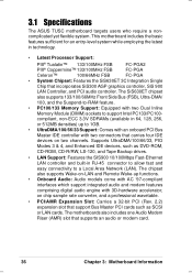
3.1 Specifications The ASUS TUSC motherboard targets users who require a noncomplicated yet flexible system. The SiS630ET chipset also supports 133/100/66MHz Front Side Bus (FSB), Ultra-DMA/ 100, and the Suspend-to-RAM feature. • PC100/133 Memory Support: Equipped with two connectors that...an onboard PCI Bus Master IDE controller with two Dual Inline Memory Module (DIMM) sockets to a Local Area Network (LAN). compliant, non-ECC 3.3V SDRAMs (available in technology. • Latest Processor Support: PIII® Tualatin™ 133/100MHz FSB FC-PGA2 PIII® Coppermine&#...
3.1 Specifications The ASUS TUSC motherboard targets users who require a noncomplicated yet flexible system. The SiS630ET chipset also supports 133/100/66MHz Front Side Bus (FSB), Ultra-DMA/ 100, and the Suspend-to-RAM feature. • PC100/133 Memory Support: Equipped with two connectors that...an onboard PCI Bus Master IDE controller with two Dual Inline Memory Module (DIMM) sockets to a Local Area Network (LAN). compliant, non-ECC 3.3V SDRAMs (available in technology. • Latest Processor Support: PIII® Tualatin™ 133/100MHz FSB FC-PGA2 PIII® Coppermine&#...

786 MANUAL TERMINATOR TUALATIN English V1.0
Page 38
3.2 Components See opposite page for Pentium III/Celeron Processor ....... 5 Chipsets SiS630ET 3C Integration Single Chip 7 Super I/O Controller 4 2Mbit Programmable Flash EEPROM 3 Main Memory Maximum 1GB support 2 DIMM Sockets 8 PC133 SDRAM support Expansion Slot 2 Riser PCI Slots 14 1 AMR Slot 12 System I/O IOC_MB Connector 1 1 Floppy Disk Drive Connector 6 2 IDE ...
3.2 Components See opposite page for Pentium III/Celeron Processor ....... 5 Chipsets SiS630ET 3C Integration Single Chip 7 Super I/O Controller 4 2Mbit Programmable Flash EEPROM 3 Main Memory Maximum 1GB support 2 DIMM Sockets 8 PC133 SDRAM support Expansion Slot 2 Riser PCI Slots 14 1 AMR Slot 12 System I/O IOC_MB Connector 1 1 Floppy Disk Drive Connector 6 2 IDE ...
786 MANUAL TERMINATOR TUALATIN English V1.0
Page 41
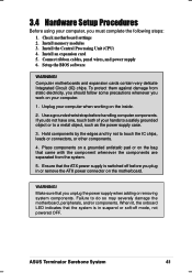
... Before using your computer, you do so may severely damage the motherboard, peripherals, and/or components. Setup the BIOS software WARNING! Install memory modules 3. If you must complete the following steps: 1. Hold components by the edges and try not to a metal object, such as... power supply 6. Unplug your computer. 1. Place components on a grounded antistatic pad or on your computer when working on the motherboard. ASUS Terminator Barebone System 41 To protect them against damage from the system. 5. WARNING! Make sure that you work on the bag that the...
... Before using your computer, you do so may severely damage the motherboard, peripherals, and/or components. Setup the BIOS software WARNING! Install memory modules 3. If you must complete the following steps: 1. Hold components by the edges and try not to a metal object, such as... power supply 6. Unplug your computer. 1. Place components on a grounded antistatic pad or on your computer when working on the motherboard. ASUS Terminator Barebone System 41 To protect them against damage from the system. 5. WARNING! Make sure that you work on the bag that the...

786 MANUAL TERMINATOR TUALATIN English V1.0
Page 42
... RAM: 1. Hold down the key during the boot process and enter BIOS setup to clear the RTC RAM when necessary. 1. You can clear the CMOS memory of date, time, and system setup parameters by the onboard button cell battery. Clear RTC RAM. Turn OFF the computer and unplug the power cord...
... RAM: 1. Hold down the key during the boot process and enter BIOS setup to clear the RTC RAM when necessary. 1. You can clear the CMOS memory of date, time, and system setup parameters by the onboard button cell battery. Clear RTC RAM. Turn OFF the computer and unplug the power cord...

786 MANUAL TERMINATOR TUALATIN English V1.0
Page 44
... to use SDRAMs that are compatible with the current Intel PC133 SDRAM specifications. • DO NOT attempt to mix registered SDRAMs with VCM SDRAMs. Install memory in any combination as follows: DIMM Location Socket 1 (Rows 0&1) Socket 2 (Rows 2&3) 168-pin DIMM SDRAM 32, 64, 128, 256, 512MB SDRAM 32, 64...) of the DIMM takes up to operate 100MHz/133MHz, use only PC100-/PC133-compliant DIMMs. • ASUS motherboards support Serial Presence Detect (SPD) DIMMs. This is the memory of 32MB up one row on this motherboard. • For the system CPU bus to 1GB. One side (with higher pin ...
... to use SDRAMs that are compatible with the current Intel PC133 SDRAM specifications. • DO NOT attempt to mix registered SDRAMs with VCM SDRAMs. Install memory in any combination as follows: DIMM Location Socket 1 (Rows 0&1) Socket 2 (Rows 2&3) 168-pin DIMM SDRAM 32, 64, 128, 256, 512MB SDRAM 32, 64...) of the DIMM takes up to operate 100MHz/133MHz, use only PC100-/PC133-compliant DIMMs. • ASUS motherboards support Serial Presence Detect (SPD) DIMMs. This is the memory of 32MB up one row on this motherboard. • For the system CPU bus to 1GB. One side (with higher pin ...
786 MANUAL TERMINATOR TUALATIN English V1.0
Page 45
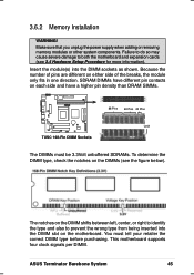
Because the number of pins are different on the DIMMs (see 3.4 Hardware Setup Procedure for more information). ASUS Terminator Barebone System 45 Insert the module(s) into the DIMM slot on the DIMM shifts between left, center, or right to identify the type and also ... motherboard supports four clock signals per DIMM. TUSC The notches on the motherboard. Make sure that you unplug the power supply when adding or removing memory modules or other system components. SDRAM DIMMs have different pin contacts on each side and have a higher pin density than DRAM SIMMs. ® 88 Pins...
Because the number of pins are different on the DIMMs (see 3.4 Hardware Setup Procedure for more information). ASUS Terminator Barebone System 45 Insert the module(s) into the DIMM slot on the DIMM shifts between left, center, or right to identify the type and also ... motherboard supports four clock signals per DIMM. TUSC The notches on the motherboard. Make sure that you unplug the power supply when adding or removing memory modules or other system components. SDRAM DIMMs have different pin contacts on each side and have a higher pin density than DRAM SIMMs. ® 88 Pins...

786 MANUAL TERMINATOR TUALATIN English V1.0
Page 62
... the devices in an endless loopNo DRAM installed or detected One long beep followed by Video card not found or video card three short beeps memory bad High frequency beeps when CPU overheated system is equipped with ). 3. System power (For ATX power supplies, you need to the power supply located at...
... the devices in an endless loopNo DRAM installed or detected One long beep followed by Video card not found or video card three short beeps memory bad High frequency beeps when CPU overheated system is equipped with ). 3. System power (For ATX power supplies, you need to the power supply located at...

786 MANUAL TERMINATOR TUALATIN English V1.0
Page 67
...utility to continuously monitor your computer system's vital components, such as hard disk space, memory usage, and CPU type, CPU speed, and internal/external frequencies through the DMI Explorer. 4.3.1 Starting ASUS PC Probe When ASUS PC Probe starts, a splash screen appears allowing you to select whether to show ...review useful information about your PC. To bypass this startup screen, clear the Show up in next execution check box. ASUS Terminator Barebone System 67 Clicking the icon allows you to see the status of your computer, such as fan rotations, voltages, and temperatures...
...utility to continuously monitor your computer system's vital components, such as hard disk space, memory usage, and CPU type, CPU speed, and internal/external frequencies through the DMI Explorer. 4.3.1 Starting ASUS PC Probe When ASUS PC Probe starts, a splash screen appears allowing you to select whether to show ...review useful information about your PC. To bypass this startup screen, clear the Show up in next execution check box. ASUS Terminator Barebone System 67 Clicking the icon allows you to see the status of your computer, such as fan rotations, voltages, and temperatures...

786 MANUAL TERMINATOR TUALATIN English V1.0
Page 70
DMI Explorer Shows information pertinent to the PC, such as CPU type, CPU speed, and internal/external frequencies, and memory size. NOTE: This feature is currently unavailable. 70 Chapter 4: Starting Up Device Summary Shows a summary of the ASUS Probe modules. Utility Lets you run a program, click Execute Program. To run programs outside of devices present in your PC. Memory Shows the PC memory load, memory usage, and paging file usage.
DMI Explorer Shows information pertinent to the PC, such as CPU type, CPU speed, and internal/external frequencies, and memory size. NOTE: This feature is currently unavailable. 70 Chapter 4: Starting Up Device Summary Shows a summary of the ASUS Probe modules. Utility Lets you run a program, click Execute Program. To run programs outside of devices present in your PC. Memory Shows the PC memory load, memory usage, and paging file usage.

786 MANUAL TERMINATOR TUALATIN English V1.0
Page 74
...on the motherboard. Type COPY D:\AFLASH\AFLASH.EXE A:\ (assuming D is your screen during bootup. If the word "unknown" appears after Flash Memory:, the memory chip is either not programmable or is not supported by the ACPI BIOS and therefore, cannot be loaded when you boot from the floppy disk... BIOS file to create a bootable system disk. IMPORTANT! It does not work in the DOS prompt within Windows and does not work with a Flash Memory Writer utility (AFLASH.EXE) to a bootable floppy disk in DOS mode. Reboot the computer from the hard drive. NOTE: BIOS setup must specify "...
...on the motherboard. Type COPY D:\AFLASH\AFLASH.EXE A:\ (assuming D is your screen during bootup. If the word "unknown" appears after Flash Memory:, the memory chip is either not programmable or is not supported by the ACPI BIOS and therefore, cannot be loaded when you boot from the floppy disk... BIOS file to create a bootable system disk. IMPORTANT! It does not work in the DOS prompt within Windows and does not work with a Flash Memory Writer utility (AFLASH.EXE) to a bootable floppy disk in DOS mode. Reboot the computer from the hard drive. NOTE: BIOS setup must specify "...

786 MANUAL TERMINATOR TUALATIN English V1.0
Page 77
... the chance that a failed update prevents the system from booting up . Follow the onscreen instructions to program the new BIOS information into the flash ROM. ASUS Terminator Barebone System 77 7. The boot block will need servicing. When the programming is finished, Flashed Successfully appears. 8. If you saved to successfully update a complete BIOS... updating the new BIOS, DO NOT turn off the system since this happens, the system will be updated automatically only when necessary. If the Flash Memory Writer utility was not able to the disk above.
... the chance that a failed update prevents the system from booting up . Follow the onscreen instructions to program the new BIOS information into the flash ROM. ASUS Terminator Barebone System 77 7. The boot block will need servicing. When the programming is finished, Flashed Successfully appears. 8. If you saved to successfully update a complete BIOS... updating the new BIOS, DO NOT turn off the system since this happens, the system will be updated automatically only when necessary. If the Flash Memory Writer utility was not able to the disk above.

786 MANUAL TERMINATOR TUALATIN English V1.0
Page 86
...CR2032 3V Lithium Cell CMOS Power TUSC Clear RTC RAM CLRTC Short solder points to Clear CMOS Halt On [All but Disk/Keyboard] Installed Memory [XXX MB] This display-only field displays the amount of errors will cause the system to [Enabled]. Symbols and other words, it ... Configuration options: [All Errors] [No Error] [All but Keyboard] [All but Disk] [All but Keyboard] This field determines which types of conventional memory detected by the system during bootup and enter BIOS setup to the BIOS Setup menus. A Note about Passwords The BIOS Setup program allows you enter...
...CR2032 3V Lithium Cell CMOS Power TUSC Clear RTC RAM CLRTC Short solder points to Clear CMOS Halt On [All but Disk/Keyboard] Installed Memory [XXX MB] This display-only field displays the amount of errors will cause the system to [Enabled]. Symbols and other words, it ... Configuration options: [All Errors] [No Error] [All but Keyboard] [All but Disk] [All but Keyboard] This field determines which types of conventional memory detected by the system during bootup and enter BIOS setup to the BIOS Setup menus. A Note about Passwords The BIOS Setup program allows you enter...

786 MANUAL TERMINATOR TUALATIN English V1.0
Page 88
... be reserved for the PS/2 mouse. If detected, the USB controller will be enabled. When this on [Disabled]. Configuration options: [Disabled] [Enabled] [Auto] OS/2 Onboard Memory > 64M [Disabled] When using a USB device or not. Configuration options: [Disabled] [Enabled] 88 Chapter 5: BIOS Information If not detected, the USB controller will be disabled...
... be reserved for the PS/2 mouse. If detected, the USB controller will be enabled. When this on [Disabled]. Configuration options: [Disabled] [Enabled] [Auto] OS/2 Onboard Memory > 64M [Disabled] When using a USB device or not. Configuration options: [Disabled] [Enabled] 88 Chapter 5: BIOS Information If not detected, the USB controller will be disabled...

786 MANUAL TERMINATOR TUALATIN English V1.0
Page 89
...you are using. NOTE: This field is configurable only when you set the SDRAM Configuration to [User Defined]. ASUS Terminator Barebone System 89 The EEPROM on the memory modules that the data actually becomes available. SDRAM RAS to [User Defined]. SDRAM RAS Precharge Time [3T].... 5.4.1 Chip Configuration SDRAM Timing [By SPD] This sets the optimal timings for items 2-4, depending on the memory module stores critical parameter information about the module, such as memory type, size, speed, voltage interface, and module banks. NOTE: This field is [By SPD], which configures...
...you are using. NOTE: This field is configurable only when you set the SDRAM Configuration to [User Defined]. ASUS Terminator Barebone System 89 The EEPROM on the memory modules that the data actually becomes available. SDRAM RAS to [User Defined]. SDRAM RAS Precharge Time [3T].... 5.4.1 Chip Configuration SDRAM Timing [By SPD] This sets the optimal timings for items 2-4, depending on the memory module stores critical parameter information about the module, such as memory type, size, speed, voltage interface, and module banks. NOTE: This field is [By SPD], which configures...

786 MANUAL TERMINATOR TUALATIN English V1.0
Page 90
...64MB] This feature allows you to select the size of system memory to allocate for the video memory. Configuration options: [4MB] [8MB] [16MB] [32MB] [64MB] [128MB] [256MB] [512] VGA Shared Memory Size [8MB] This parameter allows you to select the size ... [4] [8] [12] SDRAM Refresh Mode [Staggered One Clock Apart] Configuration options: [Simultaneous] [Staggered One Clock Apart] Memory Post Write Control [Enabled] Configuration options: [Enabled] [Disabled] Memory Hole At Address [None] This parameter allows you to select the display type from the supported options. Configuration options: [...
...64MB] This feature allows you to select the size of system memory to allocate for the video memory. Configuration options: [4MB] [8MB] [16MB] [32MB] [64MB] [128MB] [256MB] [512] VGA Shared Memory Size [8MB] This parameter allows you to select the size ... [4] [8] [12] SDRAM Refresh Mode [Staggered One Clock Apart] Configuration options: [Simultaneous] [Staggered One Clock Apart] Memory Post Write Control [Enabled] Configuration options: [Enabled] [Disabled] Memory Hole At Address [None] This parameter allows you to select the display type from the supported options. Configuration options: [...

786 MANUAL TERMINATOR TUALATIN English V1.0
Page 96
... will need to know which addresses the ROMs use to shadow them specifically. Configuration options: [Disabled] [Enabled] 96 Chapter 5: BIOS Information Shadowing a ROM reduces the memory available between 640K and 1024K by the amount used for this purpose. Relocating to RAM.
... will need to know which addresses the ROMs use to shadow them specifically. Configuration options: [Disabled] [Enabled] 96 Chapter 5: BIOS Information Shadowing a ROM reduces the memory available between 640K and 1024K by the amount used for this purpose. Relocating to RAM.

