
Terminator P4-533 English user''''s manual
Page 3
Features Table of contents Disclaimer/Copyrights 2 FCC/CDC statements 5 Safety information 6 About this guide 7 ASUS contact information 9 System package contents 10 Chapter 1: System Introduction 11 1.1 Front Panel Features 12 1.2 Rear Panel Features 13 1.3 Internal Features 14 Chapter... 2.12 Power Supply Specifications 34 2.12.1 Input Characteristics 34 2.12.2 Output Characteristics 34 2.12.3 Over-Voltage Protection (OVP 34 Chapter 3: Motherboard Information 35 3.1 Introduction 36 3.2 Motherboard components 36 3.3 Motherboard layout 39 3.4 Central Processing Unit (CPU 40 3
Features Table of contents Disclaimer/Copyrights 2 FCC/CDC statements 5 Safety information 6 About this guide 7 ASUS contact information 9 System package contents 10 Chapter 1: System Introduction 11 1.1 Front Panel Features 12 1.2 Rear Panel Features 13 1.3 Internal Features 14 Chapter... 2.12 Power Supply Specifications 34 2.12.1 Input Characteristics 34 2.12.2 Output Characteristics 34 2.12.3 Over-Voltage Protection (OVP 34 Chapter 3: Motherboard Information 35 3.1 Introduction 36 3.2 Motherboard components 36 3.3 Motherboard layout 39 3.4 Central Processing Unit (CPU 40 3

Terminator P4-533 English user''''s manual
Page 4
3.5 System memory 41 3.5.1 Memory configurations 41 3.6 Expansion slots 42 3.6.1 Configuring an expansion card 42 3.6.2 Standard Interrupt Assignments 42 3.6.3 IRQ assignments for this motherboard 42 3.7 Jumpers 43 3.8 Connectors 45 Chapter 4: BIOS Information 55 4.1 Managing and updating the BIOS 54 4.1.1 Using the computer system for the first time ............ system 90 5.2 Support CD information 90 5.2.1 Running the support CD 90 5.2.2 Installation menus 91 5.2.3 Software and drivers description 92 5.3 Software information 94 5.3.1 ASUS Update 94 5.3.2 ASUS PC Probe 96 4
3.5 System memory 41 3.5.1 Memory configurations 41 3.6 Expansion slots 42 3.6.1 Configuring an expansion card 42 3.6.2 Standard Interrupt Assignments 42 3.6.3 IRQ assignments for this motherboard 42 3.7 Jumpers 43 3.8 Connectors 45 Chapter 4: BIOS Information 55 4.1 Managing and updating the BIOS 54 4.1.1 Using the computer system for the first time ............ system 90 5.2 Support CD information 90 5.2.1 Running the support CD 90 5.2.2 Installation menus 91 5.2.3 Software and drivers description 92 5.3 Software information 94 5.3.1 ASUS Update 94 5.3.2 ASUS PC Probe 96 4

Terminator P4-533 English user''''s manual
Page 6
... connected and the power cables are unplugged. • Seek professional assistance before the signal cables are connected. • Before connecting or removing cables from the motherboard, ensure that all power cables are not damaged. If you are not sure about the voltage of the electrical outlet you detect any area where...
... connected and the power cables are unplugged. • Seek professional assistance before the signal cables are connected. • Before connecting or removing cables from the motherboard, ensure that all power cables are not damaged. If you are not sure about the voltage of the electrical outlet you detect any area where...

Terminator P4-533 English user''''s manual
Page 7
... came with the support CD. 7 It includes introduction on the front panel. 4. Chapter 3: Motherboard Information This chapter gives information about the ASUS Terminator P4 533 Barebone System. It includes detailed descriptions of the ASUS Terminator P4 533 barebone system. This guide is organized This document contains the following parts: 1. Chapter 1: System Introduction This chapter gives... chapter helps you power up your system and install drivers and utilities that came with the system.This chapter includes the motherboard layout, jumper settings, and connector locations.
... came with the support CD. 7 It includes introduction on the front panel. 4. Chapter 3: Motherboard Information This chapter gives information about the ASUS Terminator P4 533 Barebone System. It includes detailed descriptions of the ASUS Terminator P4 533 barebone system. This guide is organized This document contains the following parts: 1. Chapter 1: System Introduction This chapter gives... chapter helps you power up your system and install drivers and utilities that came with the system.This chapter includes the motherboard layout, jumper settings, and connector locations.

Terminator P4-533 English user''''s manual
Page 10
... items is damaged or missing, contact your dealer immediately. Motherboard 3. System package contents Check your package. If any of time not having to prepare all the components before starting. Barebone system 2. User's guide NOTE Optional items may not be present in your ASUS Terminator P4 533 pacakge for the following items: 1. Switching power supply 4. 1.44MB...
... items is damaged or missing, contact your dealer immediately. Motherboard 3. System package contents Check your package. If any of time not having to prepare all the components before starting. Barebone system 2. User's guide NOTE Optional items may not be present in your ASUS Terminator P4 533 pacakge for the following items: 1. Switching power supply 4. 1.44MB...

Terminator P4-533 English user''''s manual
Page 12
...Headphone Jack USB 2.0 Ports Microphone Jack Front Panel I/O Door Front Panel I/O Door The lower part of the ASUS P4SC-E motherboard, a power supply, and a floppy disk drive in the ASUS TriOptix form factor chassis. Open chassis 1 I/O door by flipping up the door. Open chassis 2 I/O door... reader. 12 Chapter 1: System Introduction NOTE On request, the optional 4-in-1 card reader may vary as shown. 1.1 Front Panel Features The ASUS Terminator P4 533 barebone system is composed of the front panel is a door that covers accessible I/O features including a CF card reader (or a 4-in-1 ...
...Headphone Jack USB 2.0 Ports Microphone Jack Front Panel I/O Door Front Panel I/O Door The lower part of the ASUS P4SC-E motherboard, a power supply, and a floppy disk drive in the ASUS TriOptix form factor chassis. Open chassis 1 I/O door by flipping up the door. Open chassis 2 I/O door... reader. 12 Chapter 1: System Introduction NOTE On request, the optional 4-in-1 card reader may vary as shown. 1.1 Front Panel Features The ASUS Terminator P4 533 barebone system is composed of the front panel is a door that covers accessible I/O features including a CF card reader (or a 4-in-1 ...

Terminator P4-533 English user''''s manual
Page 14
You will see here the standard components that come already installed in the system and the places where you remove the cover and flip out the drive frame. Game/MIDI/COM1 Extension Module Two 5.25" 3.5" HDD Drive Bays Drive Bay 3.5" Floppy Drive Modem Card (optional) Motherboard USB/audio Board Power Supply 14 Chapter 1: System Introduction 1.3 Internal Features The figure below shows the internal view of the system when you can install the other required components to get the system running.
You will see here the standard components that come already installed in the system and the places where you remove the cover and flip out the drive frame. Game/MIDI/COM1 Extension Module Two 5.25" 3.5" HDD Drive Bays Drive Bay 3.5" Floppy Drive Modem Card (optional) Motherboard USB/audio Board Power Supply 14 Chapter 1: System Introduction 1.3 Internal Features The figure below shows the internal view of the system when you can install the other required components to get the system running.
Terminator P4-533 English user''''s manual
Page 19
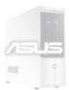
... for the Intel® Pentium® 4 478/Northwood Processor. 2.3 Install a CPU The P4SC-E motherboard comes with a surface mount 478-pin Zero Insertion Force (ZIF) socket. Locate the 478-pin CPU socket on the motherboard. 478-pin CPU socket 2. ASUS Terminator P4 533 Barebone System 19 Unlock the socket by pressing the lever sideways then lifting it...
... for the Intel® Pentium® 4 478/Northwood Processor. 2.3 Install a CPU The P4SC-E motherboard comes with a surface mount 478-pin Zero Insertion Force (ZIF) socket. Locate the 478-pin CPU socket on the motherboard. 478-pin CPU socket 2. ASUS Terminator P4 533 Barebone System 19 Unlock the socket by pressing the lever sideways then lifting it...
Terminator P4-533 English user''''s manual
Page 21
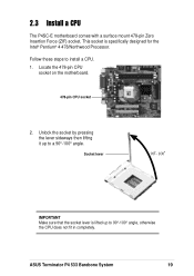
Position the fan heatsink assembly on top of the installed CPU such that the fan cable is on the motherboard (marked CPU_FAN1). 2. Snap the hook of the metal retention bracket into the hole of the heatsink. Orient the bracket such that you buy... bracket. Locking lever Retention bracket Hole on the side of the retention module. 4. Align one retention bracket with the rail on the retention module ASUS Terminator P4 533 Barebone System 21 2.4 Install the CPU heatsink and fan The Intel® Pentium® 4 478/Northwood Processor requires a specially designed heatsink and ...
Position the fan heatsink assembly on top of the installed CPU such that the fan cable is on the motherboard (marked CPU_FAN1). 2. Snap the hook of the metal retention bracket into the hole of the heatsink. Orient the bracket such that you buy... bracket. Locking lever Retention bracket Hole on the side of the retention module. 4. Align one retention bracket with the rail on the retention module ASUS Terminator P4 533 Barebone System 21 2.4 Install the CPU heatsink and fan The Intel® Pentium® 4 478/Northwood Processor requires a specially designed heatsink and ...
Terminator P4-533 English user''''s manual
Page 23
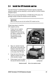
... memory The motherboard comes with a notch so that the notch on the DIMM matches the break on the motherboard. 2. These sockets support up to 2GB system memory using unbuffered ECC or non-ECC PC2700/1600/2100 DIMMs. Follow these steps to avoid damaging the DIMM. CAUTION A DDR DIMM is properly seated. ASUS Terminator P4 533 Barebone...
... memory The motherboard comes with a notch so that the notch on the DIMM matches the break on the motherboard. 2. These sockets support up to 2GB system memory using unbuffered ECC or non-ECC PC2700/1600/2100 DIMMs. Follow these steps to avoid damaging the DIMM. CAUTION A DDR DIMM is properly seated. ASUS Terminator P4 533 Barebone...
Terminator P4-533 English user''''s manual
Page 25
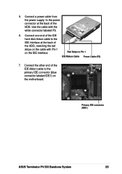
5. Use the cable with Pin 1 on the motherboard. Connect one end of the IDE hard disk ribbon cable to the IDE interface at the back of the HDD. Red Stripe to the primary IDE connector (blue connector labeled IDE1) on the IDE interface. Connect the other end of the HDD, matching the red stripe on the cable with the white connector labeled P3. 6. Connect a power cable from the power supply to the power connector at the back of the IDE ribbon cable to Pin 1 IDE Ribbon Cable Power Cable (P3) 7. Primary IDE connector (IDE1) ASUS Terminator P4 533 Barebone System 25
5. Use the cable with Pin 1 on the motherboard. Connect one end of the IDE hard disk ribbon cable to the IDE interface at the back of the HDD. Red Stripe to the primary IDE connector (blue connector labeled IDE1) on the IDE interface. Connect the other end of the HDD, matching the red stripe on the cable with the white connector labeled P3. 6. Connect a power cable from the power supply to the power connector at the back of the IDE ribbon cable to Pin 1 IDE Ribbon Cable Power Cable (P3) 7. Primary IDE connector (IDE1) ASUS Terminator P4 533 Barebone System 25

Terminator P4-533 English user''''s manual
Page 27
Use the cable with Pin 1 CD-ROM Audio Cable on the motherboard. 9. Connect one end of the IDE ribbon cable to Pin 1 Power Cable (P1) the CD-ROM. 8. Secondary IDE connector (IDE2) CD-ROM Connector (CD1) ASUS Terminator P4 533 Barebone System 27 Connect the other end of Red Stripe to the IDE ... CD-ROM audio cable to the 4-pin connector at the back of the IDE ribbon cable to the black 4-pin connector labeled CD on the motherboard. IDE Ribbon Cable 7. Connect the other end of the CD-ROM. 5. Connect a power cable from the power supply to the power connector ...
Use the cable with Pin 1 CD-ROM Audio Cable on the motherboard. 9. Connect one end of the IDE ribbon cable to Pin 1 Power Cable (P1) the CD-ROM. 8. Secondary IDE connector (IDE2) CD-ROM Connector (CD1) ASUS Terminator P4 533 Barebone System 27 Connect the other end of Red Stripe to the IDE ... CD-ROM audio cable to the 4-pin connector at the back of the IDE ribbon cable to the black 4-pin connector labeled CD on the motherboard. IDE Ribbon Cable 7. Connect the other end of the CD-ROM. 5. Connect a power cable from the power supply to the power connector ...

Terminator P4-533 English user''''s manual
Page 28
... you can install on the chassis. PCI Slot 1 (PCI1) PCI Slot 2 (PCI2) NOTE If your system came with a bracket screw. 2.8 Install a PCI expansion card The motherboard has two 32-bit PCI slots.
... you can install on the chassis. PCI Slot 1 (PCI1) PCI Slot 2 (PCI2) NOTE If your system came with a bracket screw. 2.8 Install a PCI expansion card The motherboard has two 32-bit PCI slots.

Terminator P4-533 English user''''s manual
Page 29
...* * Requires an ATX power supply. • Connect the power switch and power LED cables to their respective leads in the PANEL1 connector on the motherboard. • Connect the HDD LED cable to the 2-pin lead marked IDE_LED1. You must re-connect these cables before you were installing components. ASUS Terminator P4 533 Barebone System 29
...* * Requires an ATX power supply. • Connect the power switch and power LED cables to their respective leads in the PANEL1 connector on the motherboard. • Connect the HDD LED cable to the 2-pin lead marked IDE_LED1. You must re-connect these cables before you were installing components. ASUS Terminator P4 533 Barebone System 29

Terminator P4-533 English user''''s manual
Page 30
...contain the front panel I/O ports and the connectors to re-connect the USB cable in each module. The following illustrations show where to the motherboard. CF Card Reader module 4-in -1 card reader module (optional). UAEX module USB T: Port0 B: Port1 UAEX ® LOUT LO2 MIC... MIC2 USB2P Connect to MIC_LOUT1 connector on the motherboard Connect to USB_56 connector on the motherboard Connector locations on the motherboard The system may come with either a CF card reader module (standard) or a 4-in -1 Card Reader module ...
...contain the front panel I/O ports and the connectors to re-connect the USB cable in each module. The following illustrations show where to the motherboard. CF Card Reader module 4-in -1 card reader module (optional). UAEX module USB T: Port0 B: Port1 UAEX ® LOUT LO2 MIC... MIC2 USB2P Connect to MIC_LOUT1 connector on the motherboard Connect to USB_56 connector on the motherboard Connector locations on the motherboard The system may come with either a CF card reader module (standard) or a 4-in -1 Card Reader module ...
Terminator P4-533 English user''''s manual
Page 35
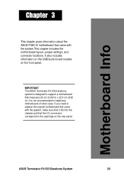
... into the chassis and that the I/O connectors correspond to the openings on the front panel. ASUS Terminator P4 533 Barebone System 35 Motherboard Info Chapter 3 This chapter gives information about the ASUS P4SC-E motherboard that came with the system.This chapter includes the motherboard layout, jumper settings, and connector locations. It also includes information on the USB/audio...
... into the chassis and that the I/O connectors correspond to the openings on the front panel. ASUS Terminator P4 533 Barebone System 35 Motherboard Info Chapter 3 This chapter gives information about the ASUS P4SC-E motherboard that came with the system.This chapter includes the motherboard layout, jumper settings, and connector locations. It also includes information on the USB/audio...
Terminator P4-533 English user''''s manual
Page 36
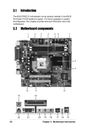
3.1 Introduction The ASUS P4SC-E motherboard comes already installed in the ASUS Terminator P4 533 barebone system. For future upgrades or system reconfiguration, this chapter provides technical information about the motherboard. 3.2 Motherboard components 1 2 3 4 56 7 8 9 12 11 10 13 14 22 21 36 20 19 18 17 16 15 Chapter 3: Motherboard information
3.1 Introduction The ASUS P4SC-E motherboard comes already installed in the ASUS Terminator P4 533 barebone system. For future upgrades or system reconfiguration, this chapter provides technical information about the motherboard. 3.2 Motherboard components 1 2 3 4 56 7 8 9 12 11 10 13 14 22 21 36 20 19 18 17 16 15 Chapter 3: Motherboard information

Terminator P4-533 English user''''s manual
Page 38
... or other devices. 15 USB 2.0 ports 0 and 1. 11 PCI slots. These two 4-pin Universal Serial Bus (USB) ports are available for a PS/2 keyboard. 38 Chapter 3: Motherboard information This audio CODEC is AC '97 compliant. 13 PS/2 mouse port. This 25-pin port connects a parallel printer, a scanner, or other audio sources. 20...
... or other devices. 15 USB 2.0 ports 0 and 1. 11 PCI slots. These two 4-pin Universal Serial Bus (USB) ports are available for a PS/2 keyboard. 38 Chapter 3: Motherboard information This audio CODEC is AC '97 compliant. 13 PS/2 mouse port. This 25-pin port connects a parallel printer, a scanner, or other audio sources. 20...

Terminator P4-533 English user''''s manual
Page 40
... transfer rate of 4.3GB/s and 3.2GB/s. The Intel NetBurst micro-architecture features the hyper-pipelined technology, rapid execution engine, 533/400MHz system bus, and execution trace cache. This socket is specifically designed for instructions on installing the Intel Pentium 4 CPU ...and the heatsink/fan assembly. 40 Chapter 3: Motherboard information 3.4 Central Processing Unit (CPU) The motherboard comes with a surface mount 478-pin Zero Insertion Force (ZIF) socket. The Intel Pentium 4 Processor in ...
... transfer rate of 4.3GB/s and 3.2GB/s. The Intel NetBurst micro-architecture features the hyper-pipelined technology, rapid execution engine, 533/400MHz system bus, and execution trace cache. This socket is specifically designed for instructions on installing the Intel Pentium 4 CPU ...and the heatsink/fan assembly. 40 Chapter 3: Motherboard information 3.4 Central Processing Unit (CPU) The motherboard comes with a surface mount 478-pin Zero Insertion Force (ZIF) socket. The Intel Pentium 4 Processor in ...

Terminator P4-533 English user''''s manual
Page 41
3.5 System memory The motherboard has two Double Data Rate (DDR) DIMM sockets that supports up to 2GB unbuffered non-ECC PC2700/2100/1600 DDR DIMMs. A DDR DIMM has the ... while an SDR DIMM is not backward compatible with SDR, and should be installed only in a socket specially designed for instructions on installing DDR DIMMs. ASUS Terminator P4 533 Barebone System 41
3.5 System memory The motherboard has two Double Data Rate (DDR) DIMM sockets that supports up to 2GB unbuffered non-ECC PC2700/2100/1600 DDR DIMMs. A DDR DIMM has the ... while an SDR DIMM is not backward compatible with SDR, and should be installed only in a socket specially designed for instructions on installing DDR DIMMs. ASUS Terminator P4 533 Barebone System 41


