

Terminator A7VT User Manual
Page 3
... 2.8 Installing an expansion card 28 2.8.1 Expansion slots 28 2.8.2 Expansion card installation 29 2.8.3 Configuring an expansion card 29 2.8.4 Standard interrupt assignments 30 2.8.5 IRQ assignments for this motherboard 30 2.9 Installing a CD-ROM drive 31 2.10 Installing a hard disk drive 33 2.11 Re-connecting cables 35 2.11.1 LED cables 35 2.11.2 UAEX module 36...
... 2.8 Installing an expansion card 28 2.8.1 Expansion slots 28 2.8.2 Expansion card installation 29 2.8.3 Configuring an expansion card 29 2.8.4 Standard interrupt assignments 30 2.8.5 IRQ assignments for this motherboard 30 2.9 Installing a CD-ROM drive 31 2.10 Installing a hard disk drive 33 2.11 Re-connecting cables 35 2.11.1 LED cables 35 2.11.2 UAEX module 36...

Terminator A7VT User Manual
Page 4
... an operating system 42 3.2 Support CD information 42 3.2.1 Running the support CD 42 3.2.2 Utilities menu 43 3.2.3 ASUS Contact information 44 3.2.4 Other information 45 3.3 Software information 47 3.3.1 ASUS PC Probe 47 3.3.2 ASUS Update 51 Chapter 4: Motherboard Info 4.1 Introduction 54 4.2 Motherboard layout 54 4.3 Jumpers 55 4.4 Connectors 58 Chapter 5: BIOS Information 5.1 Managing and updating your BIOS 66 5.1.1 Creating...
... an operating system 42 3.2 Support CD information 42 3.2.1 Running the support CD 42 3.2.2 Utilities menu 43 3.2.3 ASUS Contact information 44 3.2.4 Other information 45 3.3 Software information 47 3.3.1 ASUS PC Probe 47 3.3.2 ASUS Update 51 Chapter 4: Motherboard Info 4.1 Introduction 54 4.2 Motherboard layout 54 4.3 Jumpers 55 4.4 Connectors 58 Chapter 5: BIOS Information 5.1 Managing and updating your BIOS 66 5.1.1 Creating...
Terminator A7VT User Manual
Page 8
... parameters. 8 Chapter 3: Starting up This chapter helps you power up the system and install drivers and utilities from the support CD. 4. Chapter 4: Motherboard information This chapter gives information about the ASUS Terminator 1 barebone system. Chapter 5: BIOS information This chapter tells how to install components in the system. 3. Chapter 2: Basic installation This chapter provides...
... parameters. 8 Chapter 3: Starting up This chapter helps you power up the system and install drivers and utilities from the support CD. 4. Chapter 4: Motherboard information This chapter gives information about the ASUS Terminator 1 barebone system. Chapter 5: BIOS information This chapter tells how to install components in the system. 3. Chapter 2: Basic installation This chapter provides...

Terminator A7VT User Manual
Page 10
ASUS Terminator 1 barebone system with: • ASUS A7VT motherboard • Floppy disk drive • Optical drive (optional)* 2. User guide * CD-ROM/CD-RW/DVD-ROM/DVD-RW If any of the items is damaged or missing, contact your ASUS Terminator 1 package for the following items: 1. Support CD 4. Power cable and plug 3. System package contents Check your retailer immediately. 10
ASUS Terminator 1 barebone system with: • ASUS A7VT motherboard • Floppy disk drive • Optical drive (optional)* 2. User guide * CD-ROM/CD-RW/DVD-ROM/DVD-RW If any of the items is damaged or missing, contact your ASUS Terminator 1 package for the following items: 1. Support CD 4. Power cable and plug 3. System package contents Check your retailer immediately. 10

Terminator A7VT User Manual
Page 12
... supply, and a floppy disk drive in a stylish mini-tower casing, and is powered by the ASUS A7VT motherboard that supports AMD Athlon™ and AMD Duron™ processors. 1.2 Front panel The ASUS Terminator 1 barebone system is an optional IDE optical drive. 2. 1.1 Welcome! Optical drive. This covered slot is for a second optical drive or other 5.25...
... supply, and a floppy disk drive in a stylish mini-tower casing, and is powered by the ASUS A7VT motherboard that supports AMD Athlon™ and AMD Duron™ processors. 1.2 Front panel The ASUS Terminator 1 barebone system is an optional IDE optical drive. 2. 1.1 Welcome! Optical drive. This covered slot is for a second optical drive or other 5.25...

Terminator A7VT User Manual
Page 16
The system may come with either a PFC (Power Factor Correction) or non-PFC power supply. 3 1 4 5 2 6 7 1. Two 5.25" drive bays (Optional CD-ROM) 4. 3.5" HDD drive bay 5. 3.5" floppy drive 6. PFC/Non-PFC power supply 7. 1.4 Internal components The figure below shows the internal view of the available drive bays are pointed out. Motherboard 3. USB/audio board 16 Chapter 1: System introduction The standard components already installed in the system and the locations of the system when you remove the cover and flip out the drive frame. Game/MIDI/COM1 extension module 2.
The system may come with either a PFC (Power Factor Correction) or non-PFC power supply. 3 1 4 5 2 6 7 1. Two 5.25" drive bays (Optional CD-ROM) 4. 3.5" HDD drive bay 5. 3.5" floppy drive 6. PFC/Non-PFC power supply 7. 1.4 Internal components The figure below shows the internal view of the available drive bays are pointed out. Motherboard 3. USB/audio board 16 Chapter 1: System introduction The standard components already installed in the system and the locations of the system when you remove the cover and flip out the drive frame. Game/MIDI/COM1 extension module 2.
Terminator A7VT User Manual
Page 18
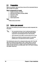
... system component. 18 Chapter 2: Basic Installation Central processing unit (CPU) 2. DDR Dual Inline Memory Module (DIMM) 3. Expansion card(s) 4. This LED lights up to install 1. The motherboard comes with the component. 2.1 Preparation Before you proceed, make sure that the standby power LED is ON, in sleep mode or in the system. Hard...
... system component. 18 Chapter 2: Basic Installation Central processing unit (CPU) 2. DDR Dual Inline Memory Module (DIMM) 3. Expansion card(s) 4. This LED lights up to install 1. The motherboard comes with the component. 2.1 Preparation Before you proceed, make sure that the standby power LED is ON, in sleep mode or in the system. Hard...

Terminator A7VT User Manual
Page 22
Locate the 462-pin ZIF socket on the socket to ensure correct installation. 2.5 Installing a CPU The motherboard comes with gold triangle) on the CPU. Take note of the marked corner (with a surface mount 462-pin Zero Insertion Force (ZIF) socket designed for the AMD Athlon™ and AMD Duron™ processors. Gold triangle CPU installation To install the CPU. 1. This mark should match a specific corner on the motherboard. 22 Chapter 2: Basic Installation
Locate the 462-pin ZIF socket on the socket to ensure correct installation. 2.5 Installing a CPU The motherboard comes with gold triangle) on the CPU. Take note of the marked corner (with a surface mount 462-pin Zero Insertion Force (ZIF) socket designed for the AMD Athlon™ and AMD Duron™ processors. Gold triangle CPU installation To install the CPU. 1. This mark should match a specific corner on the motherboard. 22 Chapter 2: Basic Installation

Terminator A7VT User Manual
Page 26
... Module (DIMM) sockets. These sockets support up to 2 GB system memory using unbuffered ECC or non-ECC PC2700/2100 DIMMs. 104 Pins 80 Pins A7VT ® DIMM2 DIMM1 A7VT 184-Pin DDR DIMM sockets 2.7.1 Memory configurations You may run only at a maximum of 266 MHz due to 333 MHz. 26 Chapter 2: Basic...
... Module (DIMM) sockets. These sockets support up to 2 GB system memory using unbuffered ECC or non-ECC PC2700/2100 DIMMs. 104 Pins 80 Pins A7VT ® DIMM2 DIMM1 A7VT 184-Pin DDR DIMM sockets 2.7.1 Memory configurations You may run only at a maximum of 266 MHz due to 333 MHz. 26 Chapter 2: Basic...
Terminator A7VT User Manual
Page 27
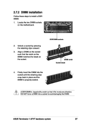
... pressing the retaining clips outward. 3. DDR DIMM sockets DIMM notch Socket break 4. ASUS Terminator 1 A7VT barebone system 27 Align a DIMM on the socket such that it fits in place and the DIMM is properly seated. A DDR DIMM is keyed with a notch so that the notch on the DIMM matches the break on the motherboard. 2.
... pressing the retaining clips outward. 3. DDR DIMM sockets DIMM notch Socket break 4. ASUS Terminator 1 A7VT barebone system 27 Align a DIMM on the socket such that it fits in place and the DIMM is properly seated. A DDR DIMM is keyed with a notch so that the notch on the DIMM matches the break on the motherboard. 2.

Terminator A7VT User Manual
Page 28
2.8 Installing an expansion card In the future, you physical injury and damage the motherboard. 28 Chapter 2: Basic Installation When you ask for one Accelerated Graphic Port (AGP) slot. Install only +1....Failure to do so may cause you may need to unplug the power cord before adding or removing expansion cards. The motherboard has one 32-bit PCI slot and one with PCI specifications AGP slot The AGP slot supports AGP 4x cards. Make..., and other cards that you buy an AGP card, make sure that comply with 1.5V specification. The motherboard does not support 3.3V AGP cards.
2.8 Installing an expansion card In the future, you physical injury and damage the motherboard. 28 Chapter 2: Basic Installation When you ask for one Accelerated Graphic Port (AGP) slot. Install only +1....Failure to do so may cause you may need to unplug the power cord before adding or removing expansion cards. The motherboard has one 32-bit PCI slot and one with PCI specifications AGP slot The AGP slot supports AGP 4x cards. Make..., and other cards that you buy an AGP card, make sure that comply with 1.5V specification. The motherboard does not support 3.3V AGP cards.

Terminator A7VT User Manual
Page 30
... Mouse Port Numeric Data Processor Primary IDE Channel Secondary IDE Channel * These IRQs are usually available for ISA or PCI devices. 2.8.5 IRQ assignments for this motherboard PCI slot AGP slot USB 1.1 UHCI 1 USB 1.1 UHCI 1 USB 1.1 UHCI 1 USB 2.0 EHCI Onboard Audio Onboard LAN ABC - shared - - - - - 2.8.4 Standard interrupt assignments IRQ Priority 0 1 1 2 2 N/A 3* 11 4* 12...
... Mouse Port Numeric Data Processor Primary IDE Channel Secondary IDE Channel * These IRQs are usually available for ISA or PCI devices. 2.8.5 IRQ assignments for this motherboard PCI slot AGP slot USB 1.1 UHCI 1 USB 1.1 UHCI 1 USB 1.1 UHCI 1 USB 2.0 EHCI Onboard Audio Onboard LAN ABC - shared - - - - - 2.8.4 Standard interrupt assignments IRQ Priority 0 1 1 2 2 N/A 3* 11 4* 12...

Terminator A7VT User Manual
Page 32
Secondary IDE connector (SEC_IDE) CD-ROM connector (CD) 32 Chapter 2: Basic Installation Use the cable with Pin 1 on the motherboard. Connect one end of the IDE ribbon cable to the black 4-pin connector labeled CD on the IDE interface. 7. CD-ROM audio cable IDE ribbon ...-ROM. 5. Connect a power cable from the power supply to the power connector at the back of the CD-ROM, matching the red stripe on the motherboard. 9.
Secondary IDE connector (SEC_IDE) CD-ROM connector (CD) 32 Chapter 2: Basic Installation Use the cable with Pin 1 on the motherboard. Connect one end of the IDE ribbon cable to the black 4-pin connector labeled CD on the IDE interface. 7. CD-ROM audio cable IDE ribbon ...-ROM. 5. Connect a power cable from the power supply to the power connector at the back of the CD-ROM, matching the red stripe on the motherboard. 9.

Terminator A7VT User Manual
Page 34
Connect a power cable from the power supply to Pin 1 IDE ribbon cable Power cable (P3) 7. Use the cable with Pin 1 on the IDE interface. Primary IDE connector (PRI_IDE) 34 Chapter 2: Basic Installation Red stripe to the power connector at the back of the HDD, matching the red stripe on the motherboard. Connect the other end of the IDE ribbon cable to the IDE interface at the back of the IDE hard disk ribbon cable to the primary IDE connector (blue connector labeled PRI_IDE1) on the cable with the white connector labeled P3. 6. 5. Connect one end of the HDD.
Connect a power cable from the power supply to Pin 1 IDE ribbon cable Power cable (P3) 7. Use the cable with Pin 1 on the IDE interface. Primary IDE connector (PRI_IDE) 34 Chapter 2: Basic Installation Red stripe to the power connector at the back of the HDD, matching the red stripe on the motherboard. Connect the other end of the IDE ribbon cable to the IDE interface at the back of the IDE hard disk ribbon cable to the primary IDE connector (blue connector labeled PRI_IDE1) on the cable with the white connector labeled P3. 6. 5. Connect one end of the HDD.
Terminator A7VT User Manual
Page 35
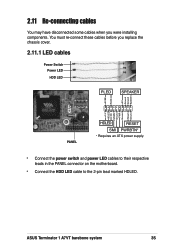
...* * Requires an ATX power supply. • Connect the power switch and power LED cables to their respective leads in the PANEL connector on the motherboard. • Connect the HDD LED cable to the 2-pin lead marked HDLED. You must re-connect these cables before you were installing components. ASUS Terminator 1 A7VT barebone system 35
...* * Requires an ATX power supply. • Connect the power switch and power LED cables to their respective leads in the PANEL connector on the motherboard. • Connect the HDD LED cable to the 2-pin lead marked HDLED. You must re-connect these cables before you were installing components. ASUS Terminator 1 A7VT barebone system 35

Terminator A7VT User Manual
Page 36
USB T: Port0 B: Port1 J1 UAEX HPHONE1 J2 MIC ® Connect to MIC_LOUT connector on the motherboard Connect to the motherboard. 2.11.2 UAEX module The system front I/O panel has a UAEX module that contains the front panel I/O ports and the connectors to USB34 connector on the motherboard Connector locations on the motherboard USB34 USB56 MIC_LOUT connector (for Microphone/Line Out cable) 36 Chapter 2: Basic Installation
USB T: Port0 B: Port1 J1 UAEX HPHONE1 J2 MIC ® Connect to MIC_LOUT connector on the motherboard Connect to the motherboard. 2.11.2 UAEX module The system front I/O panel has a UAEX module that contains the front panel I/O ports and the connectors to USB34 connector on the motherboard Connector locations on the motherboard USB34 USB56 MIC_LOUT connector (for Microphone/Line Out cable) 36 Chapter 2: Basic Installation

Terminator A7VT User Manual
Page 42
Visit the ASUS website for more information 42 Chapter3: Starting up If Autorun is enabled in this chapter for general reference only. 3.1 Installing an operating system The A7VT motherboard supports Windows® 98/ME/NT/2000/XP operating systems (OS). Refer to your OS documentation for updates. ...are subject to display more information. 3.2 Support CD information The support CD that came with the motherboard contains useful software and several utility drivers that enhance the motherboard features. Click an item to install Click an icon to change at any time without notice. ...
Visit the ASUS website for more information 42 Chapter3: Starting up If Autorun is enabled in this chapter for general reference only. 3.1 Installing an operating system The A7VT motherboard supports Windows® 98/ME/NT/2000/XP operating systems (OS). Refer to your OS documentation for updates. ...are subject to display more information. 3.2 Support CD information The support CD that came with the motherboard contains useful software and several utility drivers that enhance the motherboard features. Click an item to install Click an icon to change at any time without notice. ...
Terminator A7VT User Manual
Page 43
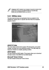
... item installs the ASUS Update. ASUS Terminator 1 A7VT barebone system 43 Simply click on a specific item then follow the installation wizard to run the CD. 3.2.2 Utilities menu The menu lists the drivers and applications that are available for this motherboard. ASUS PC Probe This smart utility monitors the fan speed, CPU temperature, and system voltages, and...
... item installs the ASUS Update. ASUS Terminator 1 A7VT barebone system 43 Simply click on a specific item then follow the installation wizard to run the CD. 3.2.2 Utilities menu The menu lists the drivers and applications that are available for this motherboard. ASUS PC Probe This smart utility monitors the fan speed, CPU temperature, and system voltages, and...

Terminator A7VT User Manual
Page 45
The screen image below is for general reference only. Motherboard Info Displays the general specifications of the motherboard. The support CD will automatically detect the motherboard information and display it on the motherboard and the contents of the support CD. Click an icon to display the specified information. ASUS Terminator 1 A7VT barebone system 45 3.2.4 Other information The icons on the top right of the screen give additional information on your screen.
The screen image below is for general reference only. Motherboard Info Displays the general specifications of the motherboard. The support CD will automatically detect the motherboard information and display it on the motherboard and the contents of the support CD. Click an icon to display the specified information. ASUS Terminator 1 A7VT barebone system 45 3.2.4 Other information The icons on the top right of the screen give additional information on your screen.
Terminator A7VT User Manual
Page 51
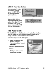
... your desired update method, then click Next. ASUS Terminator 1 A7VT barebone system 51 Select your Windows Start menu: Programs/AsusUpdate Vx.xx.xx/ AsusUpdate The ASUS Update initial screen appears. 2. ASUS PC Probe Task Bar Icon Right clicking the PC Probe icon brings up a menu to update the motherboard BIOS and drivers. Follow these steps to...
... your desired update method, then click Next. ASUS Terminator 1 A7VT barebone system 51 Select your Windows Start menu: Programs/AsusUpdate Vx.xx.xx/ AsusUpdate The ASUS Update initial screen appears. 2. ASUS PC Probe Task Bar Icon Right clicking the PC Probe icon brings up a menu to update the motherboard BIOS and drivers. Follow these steps to...


