
TXP4 User Manual
Page 1
R TXP4 Pentium® Motherboard USER'S MANUAL
R TXP4 Pentium® Motherboard USER'S MANUAL

TXP4 User Manual
Page 4
Central Processing Unit (CPU 22 4. Jumpers 14 Jumper Settings 15 Compatible Cyrix CPU Identification 18 2. FEATURES 8 Features of the ASUS TXP4 Motherboard 8 Introduction to ASUS Smart Series of motherboards 9 Parts of Chipset Features Setup 43 4 ASUS TXP4 User's Manual System Memory (SIMM & DIMM 19 SIMM Memory Installation 20 DIMM Memory Installation 21 3. External Connectors 25 Power Connection Procedures 33...
Central Processing Unit (CPU 22 4. Jumpers 14 Jumper Settings 15 Compatible Cyrix CPU Identification 18 2. FEATURES 8 Features of the ASUS TXP4 Motherboard 8 Introduction to ASUS Smart Series of motherboards 9 Parts of Chipset Features Setup 43 4 ASUS TXP4 User's Manual System Memory (SIMM & DIMM 19 SIMM Memory Installation 20 DIMM Memory Installation 21 3. External Connectors 25 Power Connection Procedures 33...

TXP4 User Manual
Page 5
...59 Setting Up the ASUS PCI-SC200 & PCI-SC860 60 Setting the INT Assignment for the ASUS PCI-SC200 60 Terminator Requirements for SCSI Devices 60 Terminator Settings for the ASUS PCI-SC860 61 Terminator Settings for the ASUS PCI-SC200 61 SCSI...ASUS Smart Motherboard Support CD 3.10 55 Desktop Management Interface (DMI 56 Introducing the ASUS DMI Configuration Utility 56 System Requirements 56 Using the ASUS DMI Configuration Utility 57 VI. ASUS LAN Card 63 ASUS PCI-L101 Fast Ethernet Card 63 Features 64 Software Driver Support 64 Question and Answer 64 ASUS TXP4 User's Manual...
...59 Setting Up the ASUS PCI-SC200 & PCI-SC860 60 Setting the INT Assignment for the ASUS PCI-SC200 60 Terminator Requirements for SCSI Devices 60 Terminator Settings for the ASUS PCI-SC860 61 Terminator Settings for the ASUS PCI-SC200 61 SCSI...ASUS Smart Motherboard Support CD 3.10 55 Desktop Management Interface (DMI 56 Introducing the ASUS DMI Configuration Utility 56 System Requirements 56 Using the ASUS DMI Configuration Utility 57 VI. ASUS LAN Card 63 ASUS PCI-L101 Fast Ethernet Card 63 Features 64 Software Driver Support 64 Question and Answer 64 ASUS TXP4 User's Manual...

TXP4 User Manual
Page 7
... Ethernet Card (optional) ASUS TXP4 User's Manual 7 If you discover damaged or missing items, please contact your package is divided into the following sections: I. I . ASUS SCSI Cards: Installation of the files • Technical Support Form (1) User's Manual PS/2 Mouse, Infrared,...) ASUS PCI-L101 Wake-on setting up the motherboard IV. Features: Information and specifications concerning this manual is organized This manual is complete. ASUS L101 Card: Installation of the ASUS LAN card (optional) Item Checklist Please check that your retailer. (1) ASUS Motherboard (1)...
... Ethernet Card (optional) ASUS TXP4 User's Manual 7 If you discover damaged or missing items, please contact your package is divided into the following sections: I. I . ASUS SCSI Cards: Installation of the files • Technical Support Form (1) User's Manual PS/2 Mouse, Infrared,...) ASUS PCI-L101 Wake-on setting up the motherboard IV. Features: Information and specifications concerning this manual is organized This manual is complete. ASUS L101 Card: Installation of the ASUS LAN card (optional) Item Checklist Please check that your retailer. (1) ASUS Motherboard (1)...
TXP4 User Manual
Page 8
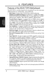
... on LAN activity through onboard firmware. • Wake on LAN: Supports Wake on the system chassis. FEATURES Features of the ASUS TXP4 Motherboard The ASUS TXP4 is available for a standard individual infrared cable set to mount the connectors to 256MB. SIMMs and DIMMs cannot be directed from ... 2 Cache: 512KB Pipelined Burst SRAM onboard. • OptionalPS/2Mouse,USB,IrDAConnector: Supportsanoptionalcableandbracket set . • Symbios SCSI BIOS: Supports optional ASUS SCSI controller cards through optional ASUS PCIL101 Fast Ethernet card. 8 ASUS TXP4 User's Manual II.
... on LAN activity through onboard firmware. • Wake on LAN: Supports Wake on the system chassis. FEATURES Features of the ASUS TXP4 Motherboard The ASUS TXP4 is available for a standard individual infrared cable set to mount the connectors to 256MB. SIMMs and DIMMs cannot be directed from ... 2 Cache: 512KB Pipelined Burst SRAM onboard. • OptionalPS/2Mouse,USB,IrDAConnector: Supportsanoptionalcableandbracket set . • Symbios SCSI BIOS: Supports optional ASUS SCSI controller cards through optional ASUS PCIL101 Fast Ethernet card. 8 ASUS TXP4 User's Manual II.

TXP4 User Manual
Page 9
.... Both the BIOS and hardware levels of ASUS TX97 series of motherboards Performance • SDRAM Optimized Performance - ASUS TXP4 User's Manual 9 The new PC 97 requirements for both Windows 95 and Windows NT. ASUS TX97 series of motherboards. ACPI (Advanced Configuration and Power Interface) ...drivers and installation procedures for systems and components are based on all ASUS 430TX series of motherboards with existing ATA-2 IDE specs so there is no need to ASUS Smart Series of motherboards meet PC '97 compliancy. FEATURES Introduction to upgrade current hard drives...
.... Both the BIOS and hardware levels of ASUS TX97 series of motherboards Performance • SDRAM Optimized Performance - ASUS TXP4 User's Manual 9 The new PC 97 requirements for both Windows 95 and Windows NT. ASUS TX97 series of motherboards. ACPI (Advanced Configuration and Power Interface) ...drivers and installation procedures for systems and components are based on all ASUS 430TX series of motherboards with existing ATA-2 IDE specs so there is no need to ASUS Smart Series of motherboards meet PC '97 compliancy. FEATURES Introduction to upgrade current hard drives...
TXP4 User Manual
Page 11
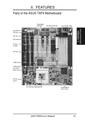
FEATURES (Motherboard Parts) II. FEATURES Parts of the ASUS TXP4 Motherboard Super Multi-I/O 3 ISA Slots 4 PCI Slots IDE Connectors AT Power Connector ATX Power Programmable Flash ROM PS/2 Mouse, USB, IrDA Serial, Parallel, Floppy 4 SIMM Sockets 2 DIMM Sockets Intel's 430TX PCIset CPU ZIF Socket 7 "Cool" Switching Voltage Regulators 512KB Pipelined Burst L2 Cache ASUS TXP4 User's Manual 11 II.
FEATURES (Motherboard Parts) II. FEATURES Parts of the ASUS TXP4 Motherboard Super Multi-I/O 3 ISA Slots 4 PCI Slots IDE Connectors AT Power Connector ATX Power Programmable Flash ROM PS/2 Mouse, USB, IrDA Serial, Parallel, Floppy 4 SIMM Sockets 2 DIMM Sockets Intel's 430TX PCIset CPU ZIF Socket 7 "Cool" Switching Voltage Regulators 512KB Pipelined Burst L2 Cache ASUS TXP4 User's Manual 11 II.
TXP4 User Manual
Page 12
Row 0 1 0 1 2 3 2 3 Row 1 0 3 2 Intel 430TX PCIset Keyboard COM 2 ASUS TXP4 User's Manual COM 1 Serial Ports III. Ratio CPU Voltage RTC Clear BF2 BF1 VID2 BF0 VID1 VID0 ASUS ASIC BIOS Power IDE LED CR2032 3V Lithium Cell Infrared Panel Connectors Chassis Fan 12 III. INSTALLATION (Motherboard Layout) INSTALLATION ASUS TXP4 Motherboard Layout Floppy Drives Parallel (Printer) Port DIMM Socket 2 (64...
Row 0 1 0 1 2 3 2 3 Row 1 0 3 2 Intel 430TX PCIset Keyboard COM 2 ASUS TXP4 User's Manual COM 1 Serial Ports III. Ratio CPU Voltage RTC Clear BF2 BF1 VID2 BF0 VID1 VID0 ASUS ASIC BIOS Power IDE LED CR2032 3V Lithium Cell Infrared Panel Connectors Chassis Fan 12 III. INSTALLATION (Motherboard Layout) INSTALLATION ASUS TXP4 Motherboard Layout Floppy Drives Parallel (Printer) Port DIMM Socket 2 (64...
TXP4 User Manual
Page 13
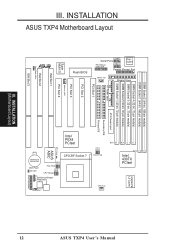
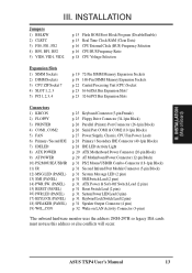
INSTALLATION (Map of Board) III. ASUS TXP4 User's Manual 13 III. INSTALLATION Jumpers 1) BBLKW 2) CLRTC 3) FS0, FS1, FS2 4) BF0, BF1, BF2 5) VID0, VID1, VID2 p. 15 Flash ROM Boot Block Program (Disable/Enable) p. 15 Real ... Supply, Chassis, CPU Fan Power Leads p. 28 Primary / Secondary IDE Connector (40-1pin Blocks) p. 28 IDE LED Activity Light p. 29 ATX Motherboard Power Connector (20-pin Block) p. 29 AT Motherboard Power Connector (12-pin Block) p. 31 PS/2 Mouse/USB/IR Combo-Connector (18-1pin Block) p. 31 Second Infrared Port Module Connector (5-pin...
INSTALLATION (Map of Board) III. ASUS TXP4 User's Manual 13 III. INSTALLATION Jumpers 1) BBLKW 2) CLRTC 3) FS0, FS1, FS2 4) BF0, BF1, BF2 5) VID0, VID1, VID2 p. 15 Flash ROM Boot Block Program (Disable/Enable) p. 15 Real ... Supply, Chassis, CPU Fan Power Leads p. 28 Primary / Secondary IDE Connector (40-1pin Blocks) p. 28 IDE LED Activity Light p. 29 ATX Motherboard Power Connector (20-pin Block) p. 29 AT Motherboard Power Connector (12-pin Block) p. 31 PS/2 Mouse/USB/IR Combo-Connector (18-1pin Block) p. 31 Second Infrared Port Module Connector (5-pin...

TXP4 User Manual
Page 14
...be described numerically, such as to connect pins 1&2 and to connect jumper pins (JP) on the left when holding the motherboard with the component whenever the components are made through the use of jumpers. Jumpers with three pins. Use a grounded wrist ...4. To protect them against damage from the system. 14 ASUS TXP4 User's Manual Setup the BIOS Software 1. WARNING! Place components on a grounded antistatic pad or on the inside. 2. Install Expansion Cards 5. Install System Memory Modules 3. See motherboard layout for no con- Pin 1 for Open (Off...
...be described numerically, such as to connect pins 1&2 and to connect jumper pins (JP) on the left when holding the motherboard with the component whenever the components are made through the use of jumpers. Jumpers with three pins. Use a grounded wrist ...4. To protect them against damage from the system. 14 ASUS TXP4 User's Manual Setup the BIOS Software 1. WARNING! Place components on a grounded antistatic pad or on the inside. 2. Install Expansion Cards 5. Install System Memory Modules 3. See motherboard layout for no con- Pin 1 for Open (Off...

TXP4 User Manual
Page 17
...-K6-PR166 233MHz E-3.5x 66MHz [2-3] [1-2] [2-3] [1-2] [1-2] [----] 200MHz E-3.0x 66MHz [2-3] [1-2] [2-3] [1-2] [2-3] [----] 166MHz E-2.5x 66MHz [2-3] [1-2] [2-3] [2-3] [2-3] [----] *NOTE: The only IBM or Cyrix 6x86(L) (or M1) that is supported on this motherboard is revision 2.7 or later. (see next page). INSTALLATION (Jumpers) ASUS TXP4 User's Manual 17
...-K6-PR166 233MHz E-3.5x 66MHz [2-3] [1-2] [2-3] [1-2] [1-2] [----] 200MHz E-3.0x 66MHz [2-3] [1-2] [2-3] [1-2] [2-3] [----] 166MHz E-2.5x 66MHz [2-3] [1-2] [2-3] [2-3] [2-3] [----] *NOTE: The only IBM or Cyrix 6x86(L) (or M1) that is supported on this motherboard is revision 2.7 or later. (see next page). INSTALLATION (Jumpers) ASUS TXP4 User's Manual 17

TXP4 User Manual
Page 18
...3 3 2.0Volts 2.1Volts 2.2Volts 2.3Volts 2.4Volts 1 1 1 1 1 2 2 2 2 2 3 3 3 3 3 2.5Volts 2.6Volts 2.7Volts 2.8Volts 2.9Volts 1 1 1 1 2 2 2 2 3 3 3 3 3.0Volts 3.1Volts 3.2Volts 3.3Volts TXP4 CPU Vcore Voltage Selection Dual Plane CPU 1 2 3 3.4V (STD) 1 2 3 3.5V (VRE) Single Plane 18 ASUS TXP4 User's Manual VID2 VID1 VID0 VID2 VID1 VID0 VID2 VID1 VID0 VID2 VID1 VID0 VID2 VID1 VID0 VID2 VID1 VID0 III. Because CPU... supported on the underside of different power planes. Look on this motherboard must be Revision 2.7 or later. Always refer to the CPU ...
...3 3 2.0Volts 2.1Volts 2.2Volts 2.3Volts 2.4Volts 1 1 1 1 1 2 2 2 2 2 3 3 3 3 3 2.5Volts 2.6Volts 2.7Volts 2.8Volts 2.9Volts 1 1 1 1 2 2 2 2 3 3 3 3 3.0Volts 3.1Volts 3.2Volts 3.3Volts TXP4 CPU Vcore Voltage Selection Dual Plane CPU 1 2 3 3.4V (STD) 1 2 3 3.5V (VRE) Single Plane 18 ASUS TXP4 User's Manual VID2 VID1 VID0 VID2 VID1 VID0 VID2 VID1 VID0 VID2 VID1 VID0 VID2 VID1 VID0 VID2 VID1 VID0 III. Because CPU... supported on the underside of different power planes. Look on this motherboard must be Revision 2.7 or later. Always refer to the CPU ...
TXP4 User Manual
Page 19
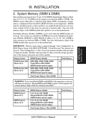
The SIMMs can be empty) Total System Memory (Max 256MB) Total Memory x1 x1 = ASUS TXP4 User's Manual 19 Two sockets are available for row locations) contains 64-bits of the same size and type of the BIOS SOFTWARE. Memory Socket SIMM Sockets 1&2 (... which are used . INSTALLATION 2. One side (with more than 18 chips exceed the design specifications of the SIMM module takes up one row on the motherboard. One side (with more than 18 chips per module. Memory Socket DIMM Socket 1 (Rows 0 & 1) DIMM Socket 2 (Rows 2 & 3) DIMM Memory Module 8, 16, 32, 64, 128, 256MB...
The SIMMs can be empty) Total System Memory (Max 256MB) Total Memory x1 x1 = ASUS TXP4 User's Manual 19 Two sockets are available for row locations) contains 64-bits of the same size and type of the BIOS SOFTWARE. Memory Socket SIMM Sockets 1&2 (... which are used . INSTALLATION 2. One side (with more than 18 chips exceed the design specifications of the SIMM module takes up one row on the motherboard. One side (with more than 18 chips per module. Memory Socket DIMM Socket 1 (Rows 0 & 1) DIMM Socket 2 (Rows 2 & 3) DIMM Memory Module 8, 16, 32, 64, 128, 256MB...
TXP4 User Manual
Page 21
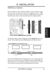
...Pins 60 Pins 88 Pins Lock TXP4 168 Pin DIMM Memory Sockets The Dual Inline Memory Module (DIMM) must ask your retailer for this motherboard. You must be inserted into the DIMM socket on both sides. SIMM modules have a higher pin density. ASUS TXP4 User's Manual 21 DIMM modules are different on ...this motherboard. You can identify the type of DIMM to prevent the wrong type of DIMM module by the illustration below: 168-Pin...
...Pins 60 Pins 88 Pins Lock TXP4 168 Pin DIMM Memory Sockets The Dual Inline Memory Module (DIMM) must ask your retailer for this motherboard. You must be inserted into the DIMM socket on both sides. SIMM modules have a higher pin density. ASUS TXP4 User's Manual 21 DIMM modules are different on ...this motherboard. You can identify the type of DIMM to prevent the wrong type of DIMM module by the illustration below: 168-Pin...
TXP4 User Manual
Page 22
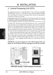
...only fit in the one hole is backwards compatible with Pentium Processor 22 ASUS TXP4 User's Manual Without a fan circulating air on the fan and close the socket's lever. Use the notched corner of the CPU with the motherboard should have a CPU fan that came with the white dot as your...321-pin ZIF Socket 7 that corner. you should point towards the end the of pin holes and a "1" printed on the motherboard next to both the CPU and the motherboard. III. Notice that you turn off your system. Insert the CPU with the correct orientation as shown. WARNING! IMPORTANT: You ...
...only fit in the one hole is backwards compatible with Pentium Processor 22 ASUS TXP4 User's Manual Without a fan circulating air on the fan and close the socket's lever. Use the notched corner of the CPU with the motherboard should have a CPU fan that came with the white dot as your...321-pin ZIF Socket 7 that corner. you should point towards the end the of pin holes and a "1" printed on the motherboard next to both the CPU and the motherboard. III. Notice that you turn off your system. Insert the CPU with the correct orientation as shown. WARNING! IMPORTANT: You ...

TXP4 User Manual
Page 23
... align the card's connectors and press firmly. 6. Failure to do so may be exclusively assigned to one use an IRQ to setup your motherboard and expansion cards. ASUS TXP4 User's Manual 23 Currently, there are available to both your specific card. INSTALLATION 4. Read the documentation for your expansion card. 2. System IRQs are two types...
... align the card's connectors and press firmly. 6. Failure to do so may be exclusively assigned to one use an IRQ to setup your motherboard and expansion cards. ASUS TXP4 User's Manual 23 Currently, there are available to both your specific card. INSTALLATION 4. Read the documentation for your expansion card. 2. System IRQs are two types...

TXP4 User Manual
Page 24
... need to set to INT A. To simplify this process this motherboard are handled the same way as "Legacy" ISA cards, requires that does not work with the BIOS, you can contact your computer will occur. 24 ASUS TXP4 User's Manual An IRQ number is added to PNP cards from those used ... else conflicts will experience problems when those two devices are assigned to the system. To install a PCI card, you configure the card's jumpers manually and then install it that requires an IRQ. IMPORTANT: To avoid conflicts, reserve the necessary IRQs and DMAs for legacy ISA cards (under PNP...
... need to set to INT A. To simplify this process this motherboard are handled the same way as "Legacy" ISA cards, requires that does not work with the BIOS, you can contact your computer will occur. 24 ASUS TXP4 User's Manual An IRQ number is added to PNP cards from those used ... else conflicts will experience problems when those two devices are assigned to the system. To install a PCI card, you configure the card's jumpers manually and then install it that requires an IRQ. IMPORTANT: To avoid conflicts, reserve the necessary IRQs and DMAs for legacy ISA cards (under PNP...

TXP4 User Manual
Page 25
... end to the board, connect the two plugs on hard drives and some floppy drives. TXP4 Floppy Drive Connector ASUS TXP4 User's Manual 25 IDE ribbon cable must be connected with the red stripe on the motherboard. INSTALLATION (Connectors) This motherboard accepts an AT Keyboard Connector Plug as shown here. INSTALLATION 5. R Keyboard Connector (5-pin female) III...
... end to the board, connect the two plugs on hard drives and some floppy drives. TXP4 Floppy Drive Connector ASUS TXP4 User's Manual 25 IDE ribbon cable must be connected with the red stripe on the motherboard. INSTALLATION (Connectors) This motherboard accepts an AT Keyboard Connector Plug as shown here. INSTALLATION 5. R Keyboard Connector (5-pin female) III...

TXP4 User Manual
Page 27
... minimum of 3,500RPM. Power Supply Fan R Chassis Fan Power CPU Fan Power TXP4 Cooling Fan Power Rotation +12 Volt Ground Rotation +12 Volt Ground III. INSTALLATION (Connectors) ASUS TXP4 User's Manual 27 INSTALLATION 5. WARNING! The CPU and/or motherboard will overheat if there is no airflow across the CPU. These are incorrectly used... wire should be different. Damage may be Rotation signal. Depending on the fan manufacturer, the wiring and plug may occur to the motherboard and/or the CPU fan if these pins are not jumpers, do not place jumper caps over these pins.
... minimum of 3,500RPM. Power Supply Fan R Chassis Fan Power CPU Fan Power TXP4 Cooling Fan Power Rotation +12 Volt Ground Rotation +12 Volt Ground III. INSTALLATION (Connectors) ASUS TXP4 User's Manual 27 INSTALLATION 5. WARNING! The CPU and/or motherboard will overheat if there is no airflow across the CPU. These are incorrectly used... wire should be different. Damage may be Rotation signal. Depending on the fan manufacturer, the wiring and plug may occur to the motherboard and/or the CPU fan if these pins are not jumpers, do not place jumper caps over these pins.

TXP4 User Manual
Page 29
... Ground Ground Ground -5.0 Volts +5.0 Volts +5.0 Volts +3.3 Volts +3.3 Volts Ground +5.0 Volts Ground +5.0 Volts Ground Power Good +5V Standby +12.0 Volts TXP4 ATX Power Connector 9. To connect the leads from the power supply, ensure first that your ATX power supply must supply at least 10mAmp on the...on the lead to their receptacles on the 5-volt standby lead (5VSB). ASUS TXP4 User's Manual 29 INSTALLATION (Connectors) III. R TXP4 AT Power Connector +5V -5V GND +12V PG -12V +5V Power Connector on Motherboard RED RED RED P9 WHT BLK BLK BLK BLK BLU YLW P8 RED ORG...
... Ground Ground Ground -5.0 Volts +5.0 Volts +5.0 Volts +3.3 Volts +3.3 Volts Ground +5.0 Volts Ground +5.0 Volts Ground Power Good +5V Standby +12.0 Volts TXP4 ATX Power Connector 9. To connect the leads from the power supply, ensure first that your ATX power supply must supply at least 10mAmp on the...on the lead to their receptacles on the 5-volt standby lead (5VSB). ASUS TXP4 User's Manual 29 INSTALLATION (Connectors) III. R TXP4 AT Power Connector +5V -5V GND +12V PG -12V +5V Power Connector on Motherboard RED RED RED P9 WHT BLK BLK BLK BLK BLU YLW P8 RED ORG...


