User Manual
Page 8
...174; 6x86MX™ (PR166 & faster), AMD-K5™ (PR75-PR133), AMD-K6™ (PR166 & faster). • Versatile Memory Support: Is equipped with four SIMM sockets to support 4-64MB 72-pin Fast Page Mode (FPM) or Extended Data Out (EDO) memory modules up . • Level 2 Cache: 512KB Pipelined Burst SRAM onboard... (Features) II. FEATURES Features of either 5.25-inch (360KB or 1.2MB) or 3.5-inch (720KB, 1.44MB, or 2.88MB) disk drives. Supports two drives of the ASUS TXP4-X Motherboard The ASUS TXP4-X is carefully designed for wireless interface. 8 ASUS TXP4-X User's Manual II.
...174; 6x86MX™ (PR166 & faster), AMD-K5™ (PR75-PR133), AMD-K6™ (PR166 & faster). • Versatile Memory Support: Is equipped with four SIMM sockets to support 4-64MB 72-pin Fast Page Mode (FPM) or Extended Data Out (EDO) memory modules up . • Level 2 Cache: 512KB Pipelined Burst SRAM onboard... (Features) II. FEATURES Features of either 5.25-inch (360KB or 1.2MB) or 3.5-inch (720KB, 1.44MB, or 2.88MB) disk drives. Supports two drives of the ASUS TXP4-X Motherboard The ASUS TXP4-X is carefully designed for wireless interface. 8 ASUS TXP4-X User's Manual II.
User Manual
Page 11
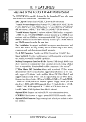
FEATURES The ASUS TXP4-X Motherboard T: PS/2 Mouse B: PS/2 Keyboard T: USB Port 1 B: USB Port 2 COM 1 T: Parallel Conn. B: Serial Conn. COM 2 Intel's 430TX PCIset 4 SIMM Sockets 2 DIMM Sockets CPU ZIF Socket 7 3 PCI Slots 512KB Pipelined Burst L2 Cache ISA/PCI Shared Slot 3 ISA Slots Programmable Flash ROM ASUS TXP4-X User's Manual 11 FEATURES (Motherboard Parts) II. II.
FEATURES The ASUS TXP4-X Motherboard T: PS/2 Mouse B: PS/2 Keyboard T: USB Port 1 B: USB Port 2 COM 1 T: Parallel Conn. B: Serial Conn. COM 2 Intel's 430TX PCIset 4 SIMM Sockets 2 DIMM Sockets CPU ZIF Socket 7 3 PCI Slots 512KB Pipelined Burst L2 Cache ISA/PCI Shared Slot 3 ISA Slots Programmable Flash ROM ASUS TXP4-X User's Manual 11 FEATURES (Motherboard Parts) II. II.
User Manual
Page 12
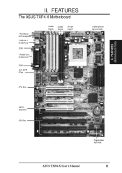
... 3 ISA Slot 4 CPU ZIF Socket 7 Intel 430TX PCIset BUS FREQ FS0 FS1 FS2 Intel PIIX4 R PCIset CR2032 3 Volt Lithium Cell BIOS Power FANPWR1 Flash ROM for ATX Power Supply CPU Voltage VID0 VID1 VID2 VID3 CPU Fan BUS Freq. INSTALLATION ASUS TXP4-X Motherboard Layout COM 1 PS/2... T: Mouse B: Keyboard USB T: USB 1 B: USB 2 FANPWR3 Board Power Input for BIOS Infrared Con. (IrDA) Panel Connections IDE LED RTC (Test/Clear) RTCLR Keyboard BIOS 12 ASUS TXP4-X User's Manual INSTALLATION (Motherboard Layout)...
... 3 ISA Slot 4 CPU ZIF Socket 7 Intel 430TX PCIset BUS FREQ FS0 FS1 FS2 Intel PIIX4 R PCIset CR2032 3 Volt Lithium Cell BIOS Power FANPWR1 Flash ROM for ATX Power Supply CPU Voltage VID0 VID1 VID2 VID3 CPU Fan BUS Freq. INSTALLATION ASUS TXP4-X Motherboard Layout COM 1 PS/2... T: Mouse B: Keyboard USB T: USB 1 B: USB 2 FANPWR3 Board Power Input for BIOS Infrared Con. (IrDA) Panel Connections IDE LED RTC (Test/Clear) RTCLR Keyboard BIOS 12 ASUS TXP4-X User's Manual INSTALLATION (Motherboard Layout)...
User Manual
Page 13
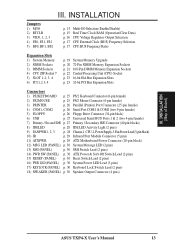
...) ASUS TXP4-X User's Manual 13 INSTALLATION Jumpers 1) M/IO 2) RTCLR 3) VID0, 1, 2, 3 4) FS0, FS1, FS2 5) BF0, BF1, BF2 p. 15 Multi-I/O Selection (Enable/Disable) p. 15 Real Time Clock RAM (Operation/Clear Data) p. 16 CPU Voltage Regulator Output Selection p. 17 CPU External Clock (BUS) Frequency Selection p. 17 CPU:BUS Frequency Ratio Expansion Slots 1) System Memory 2) SIMM Sockets...
...) ASUS TXP4-X User's Manual 13 INSTALLATION Jumpers 1) M/IO 2) RTCLR 3) VID0, 1, 2, 3 4) FS0, FS1, FS2 5) BF0, BF1, BF2 p. 15 Multi-I/O Selection (Enable/Disable) p. 15 Real Time Clock RAM (Operation/Clear Data) p. 16 CPU Voltage Regulator Output Selection p. 17 CPU External Clock (BUS) Frequency Selection p. 17 CPU:BUS Frequency Ratio Expansion Slots 1) System Memory 2) SIMM Sockets...
User Manual
Page 19
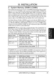
..., 32-bit SIMMs (Single Inline Memory Modules) of 4, 8, 16, 32, or 64MB to form a memory size between 8MB to 256MB. Two sockets are used, set "Auto Configuration" to 256MB. One side (with more than 24 chips per module. If both SIMMs and DIMMs at the same ...motherboard. INSTALLATION (System Memory) III. Dual Inline Memory Modules (DIMM's) can be empty) Total System Memory (Max 256MB) Total Memory x1 x1 = ASUS TXP4-X User's Manual 19 IMPORTANT: Memory speed setup is required through "Auto Configuration" in pairs so that each Row (see motherboard layout for 3.3Volt (power...
..., 32-bit SIMMs (Single Inline Memory Modules) of 4, 8, 16, 32, or 64MB to form a memory size between 8MB to 256MB. Two sockets are used, set "Auto Configuration" to 256MB. One side (with more than 24 chips per module. If both SIMMs and DIMMs at the same ...motherboard. INSTALLATION (System Memory) III. Dual Inline Memory Modules (DIMM's) can be empty) Total System Memory (Max 256MB) Total Memory x1 x1 = ASUS TXP4-X User's Manual 19 IMPORTANT: Memory speed setup is required through "Auto Configuration" in pairs so that each Row (see motherboard layout for 3.3Volt (power...
User Manual
Page 20
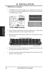
... 2 1 72 Pin SIMM Sockets 2. With your finger tips, rock the memory module into place. The plastic guides should go through the two mounting holes on the sides and the support clips should snap on one orientation as shown because of the support clips. 20 ASUS TXP4-X User's Manual The SIMM memory... modules will only fit in SIMM Socket Safety Tab (This Side Only) Mounting Hole 4. To release the memory module, push both support clips ...
... 2 1 72 Pin SIMM Sockets 2. With your finger tips, rock the memory module into place. The plastic guides should go through the two mounting holes on the sides and the support clips should snap on one orientation as shown because of the support clips. 20 ASUS TXP4-X User's Manual The SIMM memory... modules will only fit in SIMM Socket Safety Tab (This Side Only) Mounting Hole 4. To release the memory module, push both support clips ...
User Manual
Page 21
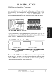
... pin contact on the DIMM module will only fit in the orientation as shown. R 88 Pins 60 Pins 20 Pins Lock 168 Pin DIMM Memory Sockets The Dual Inline Memory Module (DIMM) memory modules must ask your retailer for the specifications before purchasing. DRAM SIMM modules have a higher pin density. You... type to be 3.3Volt Unbuffered Synchronous DRAM (SDRAM) or Extended Data Output (EDO). You must be inserted into the DIMM slot on this motherboard. III. ASUS TXP4-X User's Manual 21 INSTALLATION DIMM Memory Installation Procedures: Insert the module(s) as shown.
... pin contact on the DIMM module will only fit in the orientation as shown. R 88 Pins 60 Pins 20 Pins Lock 168 Pin DIMM Memory Sockets The Dual Inline Memory Module (DIMM) memory modules must ask your retailer for the specifications before purchasing. DRAM SIMM modules have a higher pin density. You... type to be 3.3Volt Unbuffered Synchronous DRAM (SDRAM) or Extended Data Output (EDO). You must be inserted into the DIMM slot on this motherboard. III. ASUS TXP4-X User's Manual 21 INSTALLATION DIMM Memory Installation Procedures: Insert the module(s) as shown.
User Manual
Page 22
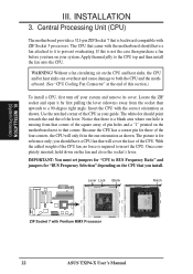
... CPU has a corner pin for "BUS Frequency Selection" depending on your guide. Lever Lock Blank 1 Notch 1 ZIF Socket 7 with the motherboard should have a CPU fan that is a blank area where one orientation as shown. INSTALLATION (System...you should point towards the end the of pin holes and a "1" printed on the fan and close the socket's lever. Once completely inserted, hold down on the motherboard next to the CPU top and then install the...R III. The CPU that came with Pentium MMX Processor 22 ASUS TXP4-X User's Manual you turn off your system and remove its cover.
... CPU has a corner pin for "BUS Frequency Selection" depending on your guide. Lever Lock Blank 1 Notch 1 ZIF Socket 7 with the motherboard should have a CPU fan that is a blank area where one orientation as shown. INSTALLATION (System...you should point towards the end the of pin holes and a "1" printed on the fan and close the socket's lever. Once completely inserted, hold down on the motherboard next to the CPU top and then install the...R III. The CPU that came with Pentium MMX Processor 22 ASUS TXP4-X User's Manual you turn off your system and remove its cover.


