TX97-LE User Manual
Page 1
R TX97-LE Pentium® Motherboard USER'S MANUAL
R TX97-LE Pentium® Motherboard USER'S MANUAL

TX97-LE User Manual
Page 4
... Setup 38 Details of Standard CMOS Setup 38 BIOS Features Setup 41 Details of BIOS Features Setup 41 Chipset Features Setup 43 Details of the ASUS TX97-LE Motherboard 11 III. INSTALLATION 12 ASUS TX97-LE Motherboard Layout 12 Installation Steps 14 1. Jumpers 14 Jumper Settings 15 Compatible Cyrix CPU Identification 18 2. CONTENTS I. FEATURES 8 Features of the...
... Setup 38 Details of Standard CMOS Setup 38 BIOS Features Setup 41 Details of BIOS Features Setup 41 Chipset Features Setup 43 Details of the ASUS TX97-LE Motherboard 11 III. INSTALLATION 12 ASUS TX97-LE Motherboard Layout 12 Installation Steps 14 1. Jumpers 14 Jumper Settings 15 Compatible Cyrix CPU Identification 18 2. CONTENTS I. FEATURES 8 Features of the...

TX97-LE User Manual
Page 5
... 64 Software Driver Support 64 Question and Answer 64 ASUS TX97-LE User's Manual 5 ASUS PCI SCSI Cards 59 Symbios SCSI BIOS and Drivers 59 ASUS PCI-SC200 & PCI-SC860 SCSI Cards 59 Setting Up the ASUS PCI-SC200 & PCI-SC860 60 Setting the INT Assignment for the ASUS PCI-SC200 60 Terminator Requirements for SCSI Devices... Defaults 50 Load Setup Defaults 50 Supervisor Password and User Password 51 IDE HDD Auto Detection 52 Save & Exit Setup 53 Exit Without Saving 53 ASUS Smart Motherboard Support CD 3.10 55 Desktop Management Interface (DMI 56 Introducing the...
... 64 Software Driver Support 64 Question and Answer 64 ASUS TX97-LE User's Manual 5 ASUS PCI SCSI Cards 59 Symbios SCSI BIOS and Drivers 59 ASUS PCI-SC200 & PCI-SC860 SCSI Cards 59 Setting Up the ASUS PCI-SC200 & PCI-SC860 60 Setting the INT Assignment for the ASUS PCI-SC200 60 Terminator Requirements for SCSI Devices... Defaults 50 Load Setup Defaults 50 Supervisor Password and User Password 51 IDE HDD Auto Detection 52 Save & Exit Setup 53 Exit Without Saving 53 ASUS Smart Motherboard Support CD 3.10 55 Desktop Management Interface (DMI 56 Introducing the...

TX97-LE User Manual
Page 7
...LAN 10/100 Ethernet Card (optional) ASUS TX97-LE User's Manual 7 ASUS SCSI Cards: Installation of the files • Technical Support Form (1) User's Manual PS/2 Mouse, Infrared, USB1, and USB2 external connector module (optional) ASUS PCI-SC200 Fast-SCSI or PCI-SC860 ...Checklist) I . Support Software: Information on setting up the motherboard IV. I . INTRODUCTION How this product III. ASUS L101 Card: Installation of the ASUS LAN card (optional) Item Checklist Please check that your retailer. (1) ASUS Motherboard (1) 9pin male serial + 25pin male serial external connector ...
...LAN 10/100 Ethernet Card (optional) ASUS TX97-LE User's Manual 7 ASUS SCSI Cards: Installation of the files • Technical Support Form (1) User's Manual PS/2 Mouse, Infrared, USB1, and USB2 external connector module (optional) ASUS PCI-SC200 Fast-SCSI or PCI-SC860 ...Checklist) I . Support Software: Information on setting up the motherboard IV. I . INTRODUCTION How this product III. ASUS L101 Card: Installation of the ASUS LAN card (optional) Item Checklist Please check that your retailer. (1) ASUS Motherboard (1) 9pin male serial + 25pin male serial external connector ...

TX97-LE User Manual
Page 8
...Floppy 3 mode" (3.5inch disk drive: 1.2MB) and LS-120 floppy disk drives (3.5-inch disk drive: 120 MB, 1.44MB, 720K). This motherboard: • Intel Chipset: Features Intel's 430TX PCIset with I /O: Provides two high-speed UART compatible serial ports and one parallel port with two...for a standard individual infrared cable set to mount the connectors to communicate within a standard protocol creating a higher level of the ASUS TX97-LE Motherboard The ASUS TX97-LE is available for the demanding PC user who wants many intelligent features in two channels, supports PIO Modes 3 and 4 and ...
...Floppy 3 mode" (3.5inch disk drive: 1.2MB) and LS-120 floppy disk drives (3.5-inch disk drive: 120 MB, 1.44MB, 720K). This motherboard: • Intel Chipset: Features Intel's 430TX PCIset with I /O: Provides two high-speed UART compatible serial ports and one parallel port with two...for a standard individual infrared cable set to mount the connectors to communicate within a standard protocol creating a higher level of the ASUS TX97-LE Motherboard The ASUS TX97-LE is available for the demanding PC user who wants many intelligent features in two channels, supports PIO Modes 3 and 4 and ...

TX97-LE User Manual
Page 9
... the IDE Transfer Speed - Each fan can be set for the future operating systems (OS) supporting OS Direct Power Management (OSPM) functionality. ASUS TX97-LE User's Manual 9 ACPI provide more Energy Saving Features for its normal RPM range and alarm thresholds. • Temperature Monitoring and Alert - II...Power Interface) is no need to avoid any failures triggered by extremely high temperature. Both the BIOS and hardware levels of ASUS TX97 series of motherboards sup- To prevent system overheat and system damage, the CPU fan and system fans are based on the following high-...
... the IDE Transfer Speed - Each fan can be set for the future operating systems (OS) supporting OS Direct Power Management (OSPM) functionality. ASUS TX97-LE User's Manual 9 ACPI provide more Energy Saving Features for its normal RPM range and alarm thresholds. • Temperature Monitoring and Alert - II...Power Interface) is no need to avoid any failures triggered by extremely high temperature. Both the BIOS and hardware levels of ASUS TX97 series of motherboards sup- To prevent system overheat and system damage, the CPU fan and system fans are based on the following high-...
TX97-LE User Manual
Page 10
...voltage levels are used up to critical motherboard components. The system resource monitor will prevent... mode. Suggestions will deactivate the CPU Clock line to decrease CPU utilization to the user. 10 ASUS TX97-LE User's Manual Voltage specifications are malfunctioning, the system will give the user information on remotely through ...a computer to implement silent PC systems. • Dual Function Power Button (requires ATX power supply) - FEATURES (TX97 Series) II. Chassis LEDs now act as Windows 95, Windows NT, and OS/2, require much more critical for more ...
...voltage levels are used up to critical motherboard components. The system resource monitor will prevent... mode. Suggestions will deactivate the CPU Clock line to decrease CPU utilization to the user. 10 ASUS TX97-LE User's Manual Voltage specifications are malfunctioning, the system will give the user information on remotely through ...a computer to implement silent PC systems. • Dual Function Power Button (requires ATX power supply) - FEATURES (TX97 Series) II. Chassis LEDs now act as Windows 95, Windows NT, and OS/2, require much more critical for more ...
TX97-LE User Manual
Page 11
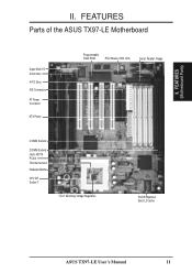
FEATURES (Motherboard Parts) II. FEATURES Parts of the ASUS TX97-LE Motherboard Super Multi-I/O 3 ISA Slots 4 PCI Slots IDE Connectors AT Power Connector ATX Power Programmable Flash ROM PS/2 Mouse, USB, IrDA Serial, Parallel, Floppy 4 SIMM Sockets 2 DIMM Sockets Intel's 430TX PCIset Thermal Sensors Hardware Monitor CPU ZIF Socket 7 "Cool" Switching Voltage Regulators 512KB Pipelined Burst L2 Cache ASUS TX97-LE User's Manual 11 II.
FEATURES (Motherboard Parts) II. FEATURES Parts of the ASUS TX97-LE Motherboard Super Multi-I/O 3 ISA Slots 4 PCI Slots IDE Connectors AT Power Connector ATX Power Programmable Flash ROM PS/2 Mouse, USB, IrDA Serial, Parallel, Floppy 4 SIMM Sockets 2 DIMM Sockets Intel's 430TX PCIset Thermal Sensors Hardware Monitor CPU ZIF Socket 7 "Cool" Switching Voltage Regulators 512KB Pipelined Burst L2 Cache ASUS TX97-LE User's Manual 11 II.
TX97-LE User Manual
Page 12
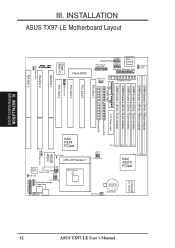
... ZIF Socket 7 CPU Voltage Switching Voltage Regulators Freq. Ratio Temp Sensor BF2 BF1 BF0 VID2 VID1 VID0 ASUS ASIC Chasis Open Alarm Infrared IDE LED Monitor LM78 Panel Connectors Chassis Fan 12 ASUS TX97-LE User's Manual INSTALLATION ASUS TX97-LE Motherboard Layout COM 1 Serial Ports Keyboard COM 2 Keyboard Power Floppy Drives Parallel (Printer) Port DIMM Socket 2 (64...
... ZIF Socket 7 CPU Voltage Switching Voltage Regulators Freq. Ratio Temp Sensor BF2 BF1 BF0 VID2 VID1 VID0 ASUS ASIC Chasis Open Alarm Infrared IDE LED Monitor LM78 Panel Connectors Chassis Fan 12 ASUS TX97-LE User's Manual INSTALLATION ASUS TX97-LE Motherboard Layout COM 1 Serial Ports Keyboard COM 2 Keyboard Power Floppy Drives Parallel (Printer) Port DIMM Socket 2 (64...

TX97-LE User Manual
Page 13
... Chassis Open Alarm Lead (4-1pin Block) p. 28 Primary / Secondary IDE Connector (40-1pin Blocks) p. 28 IDE LED Activity Light p. 29 ATX Motherboard Power Connector (20-pin Block) p. 29 AT Motherboard Power Connector (12-pin Block) p. 31 PS/2 Mouse/USB/IR Combo-Connector (18-1pin Block) p. 31 Second Infrared Port Module Connector (5-pin... monitor uses the address 290H-297H so legacy ISA cards must not use this address or else conflicts will occur. INSTALLATION (Map of Board) III. ASUS TX97-LE User's Manual 13 III.
... Chassis Open Alarm Lead (4-1pin Block) p. 28 Primary / Secondary IDE Connector (40-1pin Blocks) p. 28 IDE LED Activity Light p. 29 ATX Motherboard Power Connector (20-pin Block) p. 29 AT Motherboard Power Connector (12-pin Block) p. 31 PS/2 Mouse/USB/IR Combo-Connector (18-1pin Block) p. 31 Second Infrared Port Module Connector (5-pin... monitor uses the address 290H-297H so legacy ISA cards must not use this address or else conflicts will occur. INSTALLATION (Map of Board) III. ASUS TX97-LE User's Manual 13 III.

TX97-LE User Manual
Page 14
...WARNING! INSTALLATION (Jumpers) III. Install the Central Processing Unit (CPU) 4. Jumpers Several hardware settings are separated from yourself. See motherboard layout for no con- Pin 1 for Open (Off). Jumpers with the component whenever the components are made through the use of ...be moved together. Computer motherboards, baseboards and components, such as the power supply case. 3. Unplug your computer. 1. If you work on your computer when working on jumpers with the keyboard connector away from the system. 14 ASUS TX97-LE User's Manual Place ...
...WARNING! INSTALLATION (Jumpers) III. Install the Central Processing Unit (CPU) 4. Jumpers Several hardware settings are separated from yourself. See motherboard layout for no con- Pin 1 for Open (Off). Jumpers with the component whenever the components are made through the use of ...be moved together. Computer motherboards, baseboards and components, such as the power supply case. 3. Unplug your computer. 1. If you work on your computer when working on jumpers with the keyboard connector away from the system. 14 ASUS TX97-LE User's Manual Place ...

TX97-LE User Manual
Page 17
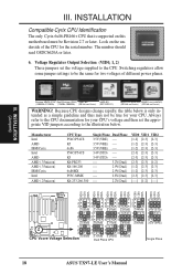
... [2-3] [1-2] [2-3] [1-2] [1-2] [----] 200MHz E-3.0x 66MHz [2-3] [1-2] [2-3] [1-2] [2-3] [----] 166MHz E-2.5x 66MHz [2-3] [1-2] [2-3] [2-3] [2-3] [----] *NOTE: The only IBM or Cyrix 6x86(L) (or M1) that is supported on this motherboard is revision 2.7 or later. (see next page). INSTALLATION (Jumpers) III. ASUS TX97-LE User's Manual 17 INSTALLATION FS2 FS1 FS0 FS2 FS1 FS0 FS2 FS1 FS0 FS2 FS1 FS0 FS2 FS1 FS0 FS2...
... [2-3] [1-2] [2-3] [1-2] [1-2] [----] 200MHz E-3.0x 66MHz [2-3] [1-2] [2-3] [1-2] [2-3] [----] 166MHz E-2.5x 66MHz [2-3] [1-2] [2-3] [2-3] [2-3] [----] *NOTE: The only IBM or Cyrix 6x86(L) (or M1) that is supported on this motherboard is revision 2.7 or later. (see next page). INSTALLATION (Jumpers) III. ASUS TX97-LE User's Manual 17 INSTALLATION FS2 FS1 FS0 FS2 FS1 FS0 FS2 FS1 FS0 FS2 FS1 FS0 FS2 FS1 FS0 FS2...
TX97-LE User Manual
Page 18
... 2.3Volts 2.4Volts 1 1 1 1 1 2 2 2 2 2 3 3 3 3 3 2.5Volts 2.6Volts 2.7Volts 2.8Volts 2.9Volts 1 1 1 1 2 2 2 2 3 3 3 3 CPU Vcore Voltage Selection 3.0Volts 3.1Volts 3.2Volts Dual Plane CPU 3.3Volts 1 2 3 3.4V (STD) 1 2 3 3.5V (VRE) Single Plane 18 ASUS TX97-LE User's Manual Because CPU designs change rapidly, the table below . III. Look on this motherboard must be true for the serial number.
... 2.3Volts 2.4Volts 1 1 1 1 1 2 2 2 2 2 3 3 3 3 3 2.5Volts 2.6Volts 2.7Volts 2.8Volts 2.9Volts 1 1 1 1 2 2 2 2 3 3 3 3 CPU Vcore Voltage Selection 3.0Volts 3.1Volts 3.2Volts Dual Plane CPU 3.3Volts 1 2 3 3.4V (STD) 1 2 3 3.5V (VRE) Single Plane 18 ASUS TX97-LE User's Manual Because CPU designs change rapidly, the table below . III. Look on this motherboard must be true for the serial number.
TX97-LE User Manual
Page 19
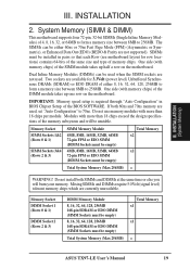
...are not supported). Modules with memory chips) of the DIMM module takes up half a row on the motherboard. Do not install both 60ns and 70ns memory are used . System Memory (SIMM & DIMM) This motherboard supports four 72-pin, 32-bit SIMMs (Single Inline Memory Modules) of 4, 8, 16, 32,...will be empty) Total System Memory (Max 256MB) Total Memory x1 x1 = ASUS TX97-LE User's Manual 19 Do not use memory modules with memory chips) of the SIMM module takes up one row on the motherboard. One side (with more than 18 chips exceed the design specifications of memory ...
...are not supported). Modules with memory chips) of the DIMM module takes up half a row on the motherboard. Do not install both 60ns and 70ns memory are used . System Memory (SIMM & DIMM) This motherboard supports four 72-pin, 32-bit SIMMs (Single Inline Memory Modules) of 4, 8, 16, 32,...will be empty) Total System Memory (Max 256MB) Total Memory x1 x1 = ASUS TX97-LE User's Manual 19 Do not use memory modules with memory chips) of the SIMM module takes up one row on the motherboard. One side (with more than 18 chips exceed the design specifications of memory ...
TX97-LE User Manual
Page 21
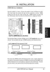
...identify the type of DIMM to be 3.3V Unbuffered for the specifications before purchasing memory modules. ASUS TX97-LE User's Manual 21 INSTALLATION DIMM Memory Installation Insert the module(s) as shown. DIMM modules are supported on this motherboard. Four clock signals are longer and have a higher pin density. R 20 Pins 60 Pins... 88 Pins Lock 168 Pin DIMM Memory Sockets The Dual Inline Memory Module (DIMM) must ask your retailer for this motherboard. You must be inserted into the DIMM socket on each side and therefore have different pin contact on the...
...identify the type of DIMM to be 3.3V Unbuffered for the specifications before purchasing memory modules. ASUS TX97-LE User's Manual 21 INSTALLATION DIMM Memory Installation Insert the module(s) as shown. DIMM modules are supported on this motherboard. Four clock signals are longer and have a higher pin density. R 20 Pins 60 Pins... 88 Pins Lock 168 Pin DIMM Memory Sockets The Dual Inline Memory Module (DIMM) must ask your retailer for this motherboard. You must be inserted into the DIMM socket on each side and therefore have different pin contact on the...
TX97-LE User Manual
Page 22
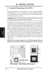
... right angle. III. INSTALLATION (CPU) III. INSTALLATION 3. Insert the CPU with Pentium Processor 22 ASUS TX97-LE User's Manual The picture is required to both the CPU and the motherboard. you should have a fan attached to it by first pulling the lever sideways away from that corner...that is not the case then purchase a fan before you install. Without a fan circulating air on the motherboard next to prevent overheating. Central Processing Unit (CPU) The motherboard provides a 321-pin ZIF Socket 7 that came with ZIF Socket 5 processors. If this is backwards compatible ...
... right angle. III. INSTALLATION (CPU) III. INSTALLATION 3. Insert the CPU with Pentium Processor 22 ASUS TX97-LE User's Manual The picture is required to both the CPU and the motherboard. you should have a fan attached to it by first pulling the lever sideways away from that corner...that is not the case then purchase a fan before you install. Without a fan circulating air on the motherboard next to prevent overheating. Central Processing Unit (CPU) The motherboard provides a 321-pin ZIF Socket 7 that came with ZIF Socket 5 processors. If this is backwards compatible ...

TX97-LE User Manual
Page 23
.... First read your expansion card documentation on your expansion card. Read the documentation for your expansion card. 3. Install the necessary software drivers for your motherboard and expansion cards. ASUS TX97-LE User's Manual 23 Remove the bracket on the slot with the screw you removed in PNP AND PCI SETUP) 9. Expansion Card Installation Procedure...
.... First read your expansion card documentation on your expansion card. Read the documentation for your expansion card. 3. Install the necessary software drivers for your motherboard and expansion cards. ASUS TX97-LE User's Manual 23 Remove the bracket on the slot with the screw you removed in PNP AND PCI SETUP) 9. Expansion Card Installation Procedure...

TX97-LE User Manual
Page 24
The PCI and PNP configuration of your computer will occur. 24 ASUS TX97-LE User's Manual You may also need to set to INT A. To simplify this process this motherboard are in the Windows directory to see a map of the BIOS setup utility can be sure that no two devices ... for those available. ISA Cards and Hardware Monitor The onboard hardware monitor uses the address 290H-297H so legacy ISA cards must not use this motherboard use a DMA (Direct Memory Access) channel. INSTALLATION (Expansion Cards) III. Since all the PCI slots on the ISA bus. Double clicking ...
The PCI and PNP configuration of your computer will occur. 24 ASUS TX97-LE User's Manual You may also need to set to INT A. To simplify this process this motherboard are in the Windows directory to see a map of the BIOS setup utility can be sure that no two devices ... for those available. ISA Cards and Hardware Monitor The onboard hardware monitor uses the address 290H-297H so legacy ISA cards must not use this motherboard use a DMA (Direct Memory Access) channel. INSTALLATION (Expansion Cards) III. Since all the PCI slots on the ISA bus. Double clicking ...
TX97-LE User Manual
Page 25
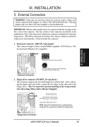
...wrong orientation when using ribbon cables with pin 5 plugged). Pin 1 is away from the first connector. 1. Floppy Drive Connector ASUS TX97-LE User's Manual 25 INSTALLATION (Connectors) This motherboard accepts an AT Keyboard Connector Plug as shown here. Keyboard Connector (KBCON, 5-pin female) This connector supports either a standard... the power connector. IMPORTANT: Ribbon cables should always be less than 18in. (46cm), with the red stripe on the motherboard. Some pins are labeled on the Pin 1 side of the ASUS Motherboard." R Keyboard Connector (5-pin female) III.
...wrong orientation when using ribbon cables with pin 5 plugged). Pin 1 is away from the first connector. 1. Floppy Drive Connector ASUS TX97-LE User's Manual 25 INSTALLATION (Connectors) This motherboard accepts an AT Keyboard Connector Plug as shown here. Keyboard Connector (KBCON, 5-pin female) This connector supports either a standard... the power connector. IMPORTANT: Ribbon cables should always be less than 18in. (46cm), with the red stripe on the motherboard. Some pins are labeled on the Pin 1 side of the ASUS Motherboard." R Keyboard Connector (5-pin female) III.
TX97-LE User Manual
Page 27
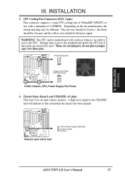
...ASUS TX97-LE User's Manual 27 Depending on the fan manufacturer, the wiring and plug may occur to the system that the chassis has been opened. Damage may be Rotation signal. Power Supply Fan R Chassis Fan Power CPU Fan Power 12Volt Chassis, CPU, Power Supply Fan Power 6. INSTALLATION 5. The CPU and/or motherboard... will indicate to the motherboard and/or the CPU fan if these pins are not jumpers, do not place jumper caps over these pins. CPU Cooling Fan ...
...ASUS TX97-LE User's Manual 27 Depending on the fan manufacturer, the wiring and plug may occur to the system that the chassis has been opened. Damage may be Rotation signal. Power Supply Fan R Chassis Fan Power CPU Fan Power 12Volt Chassis, CPU, Power Supply Fan Power 6. INSTALLATION 5. The CPU and/or motherboard... will indicate to the motherboard and/or the CPU fan if these pins are not jumpers, do not place jumper caps over these pins. CPU Cooling Fan ...


