TUWE-M User Manual
Page 1
® TUWE-M Intel® 810E2 MicroATX Motherboard USER'S MANUAL
® TUWE-M Intel® 810E2 MicroATX Motherboard USER'S MANUAL
TUWE-M User Manual
Page 2
... Rights Reserved. Product Name: ASUS TUWE-M Manual Revision: 1.01 E919 Release Date: December 2001 2 ASUS TUWE-M User's Manual USER'S NOTICE No part of this manual may or may be reproduced, transmitted, transcribed, stored in a retrieval system, or translated into any language in ...intent to the owners' benefit, without the express written permission of ASUSTeK COMPUTER INC. ("ASUS"). For previous or updated manuals, BIOS, drivers, or product release information, contact ASUS at http://www.asus.com.tw or through any means, except documentation kept by the purchaser for each product...
... Rights Reserved. Product Name: ASUS TUWE-M Manual Revision: 1.01 E919 Release Date: December 2001 2 ASUS TUWE-M User's Manual USER'S NOTICE No part of this manual may or may be reproduced, transmitted, transcribed, stored in a retrieval system, or translated into any language in ...intent to the owners' benefit, without the express written permission of ASUSTeK COMPUTER INC. ("ASUS"). For previous or updated manuals, BIOS, drivers, or product release information, contact ASUS at http://www.asus.com.tw or through any means, except documentation kept by the purchaser for each product...
TUWE-M User Manual
Page 3
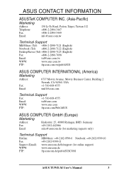
...) Notebook (Tel): +886-2-2890-7122 (English) Desktop/Server (Tel):+886-2-2890-7123 (English) Fax: +886-2-2890-7698 Email: tsd@asus.com.tw WWW: www.asus.com.tw FTP: ftp.asus.com.tw/pub/ASUS ASUS COMPUTER INTERNATIONAL (America) Marketing Address: 6737 Mowry Avenue, Mowry Business Center, Building 2 Newark, CA 94560, USA Fax: +1-510-608-4555... Fax: +49-2102-9599-11 Support (Email): www.asuscom.de/de/support (for online support) WWW: www.asuscom.de FTP: ftp.asuscom.de/pub/ASUSCOM ASUS TUWE-M User's Manual 3
...) Notebook (Tel): +886-2-2890-7122 (English) Desktop/Server (Tel):+886-2-2890-7123 (English) Fax: +886-2-2890-7698 Email: tsd@asus.com.tw WWW: www.asus.com.tw FTP: ftp.asus.com.tw/pub/ASUS ASUS COMPUTER INTERNATIONAL (America) Marketing Address: 6737 Mowry Avenue, Mowry Business Center, Building 2 Newark, CA 94560, USA Fax: +1-510-608-4555... Fax: +49-2102-9599-11 Support (Email): www.asuscom.de/de/support (for online support) WWW: www.asuscom.de FTP: ftp.asuscom.de/pub/ASUSCOM ASUS TUWE-M User's Manual 3
TUWE-M User Manual
Page 4
...26 3.7.3 Communication and Networking Riser (CNR) Slot ...... 27 3.8 External Connectors 28 3.9 Starting Up the First Time 39 4. FEATURES 8 2.1 The ASUS TUWE-M 8 2.2 TUWE-M Motherboard Components 12 3. BIOS SETUP 41 4.1 Managing and Updating Your BIOS 41 4.1.1 Upon First Use of the Computer System 41 4.1.2 Updating BIOS ... Features 52 4.4 Advanced Menu 54 4.4.1 Chip Configuration 56 4.4.2 I/O Device Configuration 58 4.4.3 PCI Configuration 60 4.5 Power Menu 62 4 ASUS TUWE-M User's Manual INTRODUCTION 7 1.1 How This Manual Is Organized 7 1.2 Item Checklist 7 2. CONTENTS 1.
...26 3.7.3 Communication and Networking Riser (CNR) Slot ...... 27 3.8 External Connectors 28 3.9 Starting Up the First Time 39 4. FEATURES 8 2.1 The ASUS TUWE-M 8 2.2 TUWE-M Motherboard Components 12 3. BIOS SETUP 41 4.1 Managing and Updating Your BIOS 41 4.1.1 Upon First Use of the Computer System 41 4.1.2 Updating BIOS ... Features 52 4.4 Advanced Menu 54 4.4.1 Chip Configuration 56 4.4.2 I/O Device Configuration 58 4.4.3 PCI Configuration 60 4.5 Power Menu 62 4 ASUS TUWE-M User's Manual INTRODUCTION 7 1.1 How This Manual Is Organized 7 1.2 Item Checklist 7 2. CONTENTS 1.
TUWE-M User Manual
Page 5
SOFTWARE REFERENCE 72 6.1 ASUS PC Probe 73 6.2 ASUS Live Update 78 6.3 CyberLink PowerPlayer SE 79 6.4 CyberLink VideoLive Mail 80 6.5 3Deep Color Tuner 82 5. SOFTWARE SETUP 71 5.1 Install Operating System 71 5.2 Start Windows 71 5.3 TUWE-M Motherboard Support CD 72 5.3.1 Installation Menu 72 6. CONTENTS 4.5.1 Power Up Control 64 4.5.2 Hardware Monitor 66 4.6 Boot Menu 67 4.7 Exit Menu 69 5. APPENDIX 85 7.1 Glossary 85 INDEX 89 ASUS TUWE-M User's Manual 5
SOFTWARE REFERENCE 72 6.1 ASUS PC Probe 73 6.2 ASUS Live Update 78 6.3 CyberLink PowerPlayer SE 79 6.4 CyberLink VideoLive Mail 80 6.5 3Deep Color Tuner 82 5. SOFTWARE SETUP 71 5.1 Install Operating System 71 5.2 Start Windows 71 5.3 TUWE-M Motherboard Support CD 72 5.3.1 Installation Menu 72 6. CONTENTS 4.5.1 Power Up Control 64 4.5.2 Hardware Monitor 66 4.6 Boot Menu 67 4.7 Exit Menu 69 5. APPENDIX 85 7.1 Glossary 85 INDEX 89 ASUS TUWE-M User's Manual 5
TUWE-M User Manual
Page 6
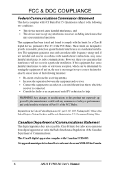
...the limits for help. Cet appareil numérique de la classe B est conforme à la norme NMB-003 du Canada. 6 ASUS TUWE-M User's Manual This equipment generates, uses and can be determined by turning the equipment off and on a circuit different from digital apparatus set out in the...relocate the receiving antenna. • Increase the separation between the equipment and receiver. • Connect the equipment to an outlet on , the user is encouraged to try to radio or television reception, which can radiate radio frequency energy and, if not installed and used in a particular ...
...the limits for help. Cet appareil numérique de la classe B est conforme à la norme NMB-003 du Canada. 6 ASUS TUWE-M User's Manual This equipment generates, uses and can be determined by turning the equipment off and on a circuit different from digital apparatus set out in the...relocate the receiving antenna. • Increase the separation between the equipment and receiver. • Connect the equipment to an outlet on , the user is encouraged to try to radio or television reception, which can radiate radio frequency energy and, if not installed and used in a particular ...
TUWE-M User Manual
Page 7
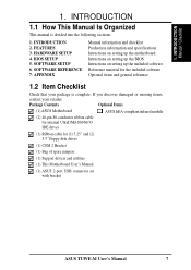
... (1) COM 2 Bracket (1) Bag of spare jumpers (1) Support drivers and utilities (1) This Motherboard User's Manual (1) ASUS 2-port USB connector set with bracket ASUS TUWE-M User's Manual 7 HARDWARE SETUP 4. Package Contents Optional Items (1) ASUS Motherboard (2) 40-pin 80-conductor ribbon cable for internal UltraDMA100/66/33 IDE drives ASUS IrDA-compliant infrared module (1) Ribbon cable for the included software Optional items...
... (1) COM 2 Bracket (1) Bag of spare jumpers (1) Support drivers and utilities (1) This Motherboard User's Manual (1) ASUS 2-port USB connector set with bracket ASUS TUWE-M User's Manual 7 HARDWARE SETUP 4. Package Contents Optional Items (1) ASUS Motherboard (2) 40-pin 80-conductor ribbon cable for internal UltraDMA100/66/33 IDE drives ASUS IrDA-compliant infrared module (1) Ribbon cable for the included software Optional items...
TUWE-M User Manual
Page 8
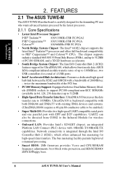
...rates of the PCI bus. • PC100 Memory Support: Equipped with EPP and ECP capabilities. FEATURES 2.1 The ASUS TUWE-M The ASUS TUWE-M motherboard is integrated through the Intel I /O: Provides two high-speed UART compatible serial ports and one parallel port...SDRAM frequency adjustments, boot block write protection, and HD/SCSI/MO/ ZIP/CD/Floppy boot. 8 ASUS TUWE-M User's Manual FEATURES Specifications 2. two USB controllers for the demanding PC user who wants advanced features processed by the fastest processors. 2.1.1 Core Specifications • Latest Intel Processor Support...
...rates of the PCI bus. • PC100 Memory Support: Equipped with EPP and ECP capabilities. FEATURES 2.1 The ASUS TUWE-M The ASUS TUWE-M motherboard is integrated through the Intel I /O: Provides two high-speed UART compatible serial ports and one parallel port...SDRAM frequency adjustments, boot block write protection, and HD/SCSI/MO/ ZIP/CD/Floppy boot. 8 ASUS TUWE-M User's Manual FEATURES Specifications 2. two USB controllers for the demanding PC user who wants advanced features processed by the fastest processors. 2.1.1 Core Specifications • Latest Intel Processor Support...
TUWE-M User Manual
Page 9
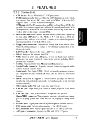
... TV or monitor. • RJ-45: Supports the onboard Intel NIC. • USB: Supports up to four Ultra DMA/100/66, PIO Modes 3 & 4 IDE devices. ASUS TUWE-M User's Manual 9 one port is a mid-board header. • IrDA: Integrated IR supports a remote control package for pointers, printers, etc; 2. One side of the connector is for...
... TV or monitor. • RJ-45: Supports the onboard Intel NIC. • USB: Supports up to four Ultra DMA/100/66, PIO Modes 3 & 4 IDE devices. ASUS TUWE-M User's Manual 9 one port is a mid-board header. • IrDA: Integrated IR supports a remote control package for pointers, printers, etc; 2. One side of the connector is for...
TUWE-M User Manual
Page 10
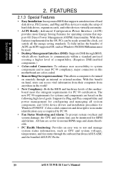
... an internal or external modem. FEATURES Special Features 2. To fully utilize the benefits of compatibility. (Requires DMI-enabled components.) • Color-coded Connectors: To enhance user accessibility to system components and to be monitored for Windows95/98/NT . With these features implemented in the OS, PCs can access vital information from... easy way to make identification easy as Windows 98/2000/Millenium must be used. • Desktop Management Interface (DMI): Supports DMI through the onboard hardware ASUS ASIC and the bundled ASUS PC Probe. 10 ASUS TUWE-M User's Manual
... an internal or external modem. FEATURES Special Features 2. To fully utilize the benefits of compatibility. (Requires DMI-enabled components.) • Color-coded Connectors: To enhance user accessibility to system components and to be monitored for Windows95/98/NT . With these features implemented in the OS, PCs can access vital information from... easy way to make identification easy as Windows 98/2000/Millenium must be used. • Desktop Management Interface (DMI): Supports DMI through the onboard hardware ASUS ASIC and the bundled ASUS PC Probe. 10 ASUS TUWE-M User's Manual
TUWE-M User Manual
Page 11
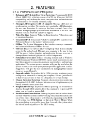
... possible application crashes. This function requires ACPI OS and driver support. • Wake-On-Ring: Supports Wake-On-Ring through the ASUS ASIC. ASUS TUWE-M User's Manual 11 The system resource monitor will give the user information on battery power for virtually automatic setup. • Message LED (requires ACPI OS support): Message LEDs now act as...
... possible application crashes. This function requires ACPI OS and driver support. • Wake-On-Ring: Supports Wake-On-Ring through the ASUS ASIC. ASUS TUWE-M User's Manual 11 The system resource monitor will give the user information on battery power for virtually automatic setup. • Message LED (requires ACPI OS support): Message LEDs now act as...
TUWE-M User Manual
Page 12
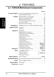
...1 Floppy Disk Drive Connector 5 2 IDE Connectors (ATA100 Support 6 1 Serial COM2 Header 21 1 USB Connector (2 and 3 10 1 IrDA Connector 9 1 ASUS Special Audio Connector 18 1 LCDTV Header 22 1 Parallel Port Connector 24 1 Serial COM1 Port Connector Bottom) 25 2 USB Port Connectors (0 and 1 Bottom) 26...20 1 Microphone Connector Network Features 1 RJ-45 Connector Top) 26 Hardware Monitoring System Voltage Monitoring (integrated in ASUS ASIC) ....... 13 Power ATX Power Supply Connector 1 Special Feature Onboard LED 7 Form Factor MicroATX 12 ASUS TUWE-M User's Manual
...1 Floppy Disk Drive Connector 5 2 IDE Connectors (ATA100 Support 6 1 Serial COM2 Header 21 1 USB Connector (2 and 3 10 1 IrDA Connector 9 1 ASUS Special Audio Connector 18 1 LCDTV Header 22 1 Parallel Port Connector 24 1 Serial COM1 Port Connector Bottom) 25 2 USB Port Connectors (0 and 1 Bottom) 26...20 1 Microphone Connector Network Features 1 RJ-45 Connector Top) 26 Hardware Monitoring System Voltage Monitoring (integrated in ASUS ASIC) ....... 13 Power ATX Power Supply Connector 1 Special Feature Onboard LED 7 Form Factor MicroATX 12 ASUS TUWE-M User's Manual
TUWE-M User Manual
Page 14
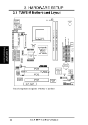
3. HARDWARE SETUP 3.1 TUWE-M Motherboard Layout DIMM1 (64/72 bit, 168-pin module) DIMM2 (64/72 bit, 168-pin module) FLOPPY SECONDARY IDE PRIMARY IDE PS/2KBMS T: Mouse B: Keyboard ... AUD_EN1 ® PCI1 TUWE-M PCI2 Intel 82562 LAN PCI3 CNR_SLOT DSW LED1 01 23 1 1 1 IrDA CR2032 3V Lithium Cell CMOS Power Intel I/O Controller Hub (ICH2) CLRTC 2Mbit Firmware Hub (FWH) USB2 ASUS ASIC CNRUSB1 CNRUSB2 ACHA USBPWR2 SMB PANEL IDELED Grayed components are optional at the time of purchase. 14 ASUS TUWE-M User's Manual H/W SETUP Motherboard...
3. HARDWARE SETUP 3.1 TUWE-M Motherboard Layout DIMM1 (64/72 bit, 168-pin module) DIMM2 (64/72 bit, 168-pin module) FLOPPY SECONDARY IDE PRIMARY IDE PS/2KBMS T: Mouse B: Keyboard ... AUD_EN1 ® PCI1 TUWE-M PCI2 Intel 82562 LAN PCI3 CNR_SLOT DSW LED1 01 23 1 1 1 IrDA CR2032 3V Lithium Cell CMOS Power Intel I/O Controller Hub (ICH2) CLRTC 2Mbit Firmware Hub (FWH) USB2 ASUS ASIC CNRUSB1 CNRUSB2 ACHA USBPWR2 SMB PANEL IDELED Grayed components are optional at the time of purchase. 14 ASUS TUWE-M User's Manual H/W SETUP Motherboard...
TUWE-M User Manual
Page 15
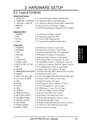
... CPU,PowerSupply,ChassisFanConnectors(Three3 pins) 14) CD1, AUX, MODEM p.34 Internal Audio Connectors (Four 4 pins) 15) IrDA p.34 Infrared Connector (10-1 pins) 16) AUDIO p.35 ASUS Special Audio Connector (12-1 pins) 17) LCDTV p.36 LCD-TV Headers (18-1 pins / 18 pins) 18) USB2 p.36 USB Headers (5-1 pins, Two 10-1 pins) 19... System Management Interrupt Switch Lead (2 pins) 25) PWRSW (PANEL) p.38 ATX Power / Soft-Off Switch Lead (2 pins) 26) RESET (PANEL) p.38 Reset Switch Lead (2 pins) ASUS TUWE-M User's Manual 15 H/W SETUP Layout Contents 3. 3.
... CPU,PowerSupply,ChassisFanConnectors(Three3 pins) 14) CD1, AUX, MODEM p.34 Internal Audio Connectors (Four 4 pins) 15) IrDA p.34 Infrared Connector (10-1 pins) 16) AUDIO p.35 ASUS Special Audio Connector (12-1 pins) 17) LCDTV p.36 LCD-TV Headers (18-1 pins / 18 pins) 18) USB2 p.36 USB Headers (5-1 pins, Two 10-1 pins) 19... System Management Interrupt Switch Lead (2 pins) 25) PWRSW (PANEL) p.38 ATX Power / Soft-Off Switch Lead (2 pins) 26) RESET (PANEL) p.38 Reset Switch Lead (2 pins) ASUS TUWE-M User's Manual 15 H/W SETUP Layout Contents 3. 3.
TUWE-M User Manual
Page 16
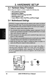
...-off before handling computer components. Place components on a grounded antistatic pad or on the inside. 2. H/W SETUP Layout Contents LED1 ® TUWE-M TUWE-M Onboard LED ON Standby Power OFF Powered Off 16 ASUS TUWE-M User's Manual HARDWARE SETUP 3.3 Hardware Setup Procedure Before using your computer when working on the bag that the system is switched off mode...
...-off before handling computer components. Place components on a grounded antistatic pad or on the inside. 2. H/W SETUP Layout Contents LED1 ® TUWE-M TUWE-M Onboard LED ON Standby Power OFF Powered Off 16 ASUS TUWE-M User's Manual HARDWARE SETUP 3.3 Hardware Setup Procedure Before using your computer when working on the bag that the system is switched off mode...
TUWE-M User Manual
Page 17
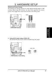
... motherboard's onboard functions are either adjusted through jumpers or DIP switches. Frequency Selection 2. Frequency Selection 3. When using this jumper. ® TUWE-M TUWE-M Audio Codec Setting AUD_EN1 12 23 Enable (Default) Disable ASUS TUWE-M User's Manual 17 3. Frequency Selection. 1) Onboard PCI Audio Setting (AUDIO_EN) The onboard PCI audio may be enable or disabled using DIP switches, the...
... motherboard's onboard functions are either adjusted through jumpers or DIP switches. Frequency Selection 2. Frequency Selection 3. When using this jumper. ® TUWE-M TUWE-M Audio Codec Setting AUD_EN1 12 23 Enable (Default) Disable ASUS TUWE-M User's Manual 17 3. Frequency Selection. 1) Onboard PCI Audio Setting (AUDIO_EN) The onboard PCI audio may be enable or disabled using DIP switches, the...

TUWE-M User Manual
Page 18
...current consumed must be set in conjunction with Wake On USB for STR State in the sleep mode. H/W SETUP Motherboard Settings 18 ASUS TUWE-M User's Manual Set these jumpers must be set to Enable. 2. Your computer will not power ON if you set to use your computer. ...Setting Disable Enable USBPWR01, USBPWR23 [1-2] (default) [2-3] USBPWR1 12 23 ® TUWE-M TUWE-M USB Device Wake Up +5V (Default) +5VSB USBPWR2 12 23 +5V (Default) +5VSB 3. HARDWARE SETUP 2) USB Device Wake Up (USBPWR01, USBPWR23)...
...current consumed must be set in conjunction with Wake On USB for STR State in the sleep mode. H/W SETUP Motherboard Settings 18 ASUS TUWE-M User's Manual Set these jumpers must be set to Enable. 2. Your computer will not power ON if you set to use your computer. ...Setting Disable Enable USBPWR01, USBPWR23 [1-2] (default) [2-3] USBPWR1 12 23 ® TUWE-M TUWE-M USB Device Wake Up +5V (Default) +5VSB USBPWR2 12 23 +5V (Default) +5VSB 3. HARDWARE SETUP 2) USB Device Wake Up (USBPWR01, USBPWR23)...
TUWE-M User Manual
Page 19
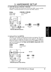
... 4.5.1 Power Up Control. Setting KBPWR Enable [1-2] (default) Disable [2-3] KBPWR ® TUWE-M 12 Enable (default) 23 Disable TUWE-M Keyboard Power Setting ASUS TUWE-M User's Manual 19 Pressing the powers up from the keyboard. H/W SETUP Motherboard Settings ® TUWE-M 12 CNRUSB1 CNRUSB2 USB2 Connect (default) CNRUSB1 CNRUSB2 23 CNR TUWE-M USB/CNR Selection 4) Keyboard Power Up (KBPWR) This allows you...
... 4.5.1 Power Up Control. Setting KBPWR Enable [1-2] (default) Disable [2-3] KBPWR ® TUWE-M 12 Enable (default) 23 Disable TUWE-M Keyboard Power Setting ASUS TUWE-M User's Manual 19 Pressing the powers up from the keyboard. H/W SETUP Motherboard Settings ® TUWE-M 12 CNRUSB1 CNRUSB2 USB2 Connect (default) CNRUSB1 CNRUSB2 23 CNR TUWE-M USB/CNR Selection 4) Keyboard Power Up (KBPWR) This allows you...

TUWE-M User Manual
Page 20
asus.com.tw 20 ASUS TUWE-M User's Manual DSW ® TUWE-M CPU 66MHz 100MHz 133MHz SDRAM 100MHz 100MHz 100MHz TUWE-M CPU External Clock (BUS) Frequency Selection Frequency Selection Table SDRAM (MHz) 105 100 112 102 105 110 101 124 105 101 112 125 CPU (MHz) 1 ...] [ON] [ON] [ON] [OFF] [OFF] [OFF] [OFF] 5 [ON] [ON] [ON] [ON] [OFF] [OFF] [OFF] [OFF] [OFF] [OFF] [OFF] [OFF] For updated processor settings, visit the ASUS web site: www. HARDWARE SETUP 5) CPU External Frequency Setting (DSW) This option tells the clock generator what frequency to send to the CPU, DRAM, AGP...
asus.com.tw 20 ASUS TUWE-M User's Manual DSW ® TUWE-M CPU 66MHz 100MHz 133MHz SDRAM 100MHz 100MHz 100MHz TUWE-M CPU External Clock (BUS) Frequency Selection Frequency Selection Table SDRAM (MHz) 105 100 112 102 105 110 101 124 105 101 112 125 CPU (MHz) 1 ...] [ON] [ON] [ON] [OFF] [OFF] [OFF] [OFF] 5 [ON] [ON] [ON] [ON] [OFF] [OFF] [OFF] [OFF] [OFF] [OFF] [OFF] [OFF] For updated processor settings, visit the ASUS web site: www. HARDWARE SETUP 5) CPU External Frequency Setting (DSW) This option tells the clock generator what frequency to send to the CPU, DRAM, AGP...
TUWE-M User Manual
Page 21
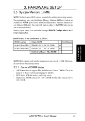
... in 32, 64, 128, 256MB. 3. Otherwise, the system may hang during startup. 3.5.1 General DIMM Notes • ASUS motherboards support SPD (Serial Presence Detect) DIMMs. This is required after adding or removing memory. H/W SETUP Memory Installation ASUS TUWE-M User's Manual 21 Sockets are available for best performance vs. stability. • BIOS shows SDRAM memory on the...
... in 32, 64, 128, 256MB. 3. Otherwise, the system may hang during startup. 3.5.1 General DIMM Notes • ASUS motherboards support SPD (Serial Presence Detect) DIMMs. This is required after adding or removing memory. H/W SETUP Memory Installation ASUS TUWE-M User's Manual 21 Sockets are available for best performance vs. stability. • BIOS shows SDRAM memory on the...

