User Guide
Page 4
... to the server 3-2 3.3 Attaching the rails to the rack 3-3 3.4 Mounting the server to the rack 3-4 Chapter 4: Motherboard Info 4.1 Motherboard layout 4-2 4.2 Jumpers 4-4 4.3 Internal connectors 4-9 4.4 Internal LEDs 4-17 Chapter 5: BIOS setup 5.1 Managing and updating your BIOS 5-2 5.1.1 AFUDOS utility 5-2 5.1.2 ASUS CrashFree BIOS 3 utility 5-4 5.2 BIOS setup program 5-5 5.2.1 BIOS menu screen 5-6 5.2.2 Menu bar 5-6 5.2.3 Navigation keys 5-6 5.2.4 Menu items 5-7 5.2.5 Sub...
... to the server 3-2 3.3 Attaching the rails to the rack 3-3 3.4 Mounting the server to the rack 3-4 Chapter 4: Motherboard Info 4.1 Motherboard layout 4-2 4.2 Jumpers 4-4 4.3 Internal connectors 4-9 4.4 Internal LEDs 4-17 Chapter 5: BIOS setup 5.1 Managing and updating your BIOS 5-2 5.1.1 AFUDOS utility 5-2 5.1.2 ASUS CrashFree BIOS 3 utility 5-4 5.2 BIOS setup program 5-5 5.2.1 BIOS menu screen 5-6 5.2.2 Menu bar 5-6 5.2.3 Navigation keys 5-6 5.2.4 Menu items 5-7 5.2.5 Sub...
User Guide
Page 9
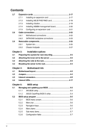
...1: Product Introduction This chapter describes the general features of the jumpers and internal connectors. 5. Chapter 4: Motherboard information This chapter includes the motherboard layout and brief descriptions of the server, including sections on front panel and rear panel specifications. 2. This... This chapter provides instructions for installing the necessary drivers for disposal of configuring a server. ix DO NOT throw the motherboard in municipal waste. Check local regulations for different system components. About this guide Audience This user guide is intended for...
...1: Product Introduction This chapter describes the general features of the jumpers and internal connectors. 5. Chapter 4: Motherboard information This chapter includes the motherboard layout and brief descriptions of the server, including sections on front panel and rear panel specifications. 2. This... This chapter provides instructions for installing the necessary drivers for disposal of configuring a server. ix DO NOT throw the motherboard in municipal waste. Check local regulations for different system components. About this guide Audience This user guide is intended for...
User Guide
Page 12
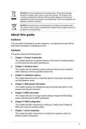
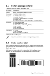
...note of the above items is damaged or missing, contact your problems. TS500-E6/PS4 xxxxxxxxxxxx 1-2 Chapter 1: Product introduction Rear: 1 x 120mm x 38mm) Accessories 1 x TS500-E6 User's Guide 1 x ASUS ASWM 2.0 User's Guide 1 x TS500-E6 Support CD (including ASWM*) 1 x Bag of Screws 1 x AC ...12 characters such as xxxxxxxxxxxx. 1.1 System package contents Check your system package for the following items. Model Name TS500-E6/PS4 Chassis ASUS T50A Pedestal 5U Rackmount Chassis Motherboard ASUS Z8NA-D6 Server Board Component 1 x 470W Single Power Supply 4 x hot-swap HDD trays 1 x SAS...
...note of the above items is damaged or missing, contact your problems. TS500-E6/PS4 xxxxxxxxxxxx 1-2 Chapter 1: Product introduction Rear: 1 x 120mm x 38mm) Accessories 1 x TS500-E6 User's Guide 1 x ASUS ASWM 2.0 User's Guide 1 x TS500-E6 Support CD (including ASWM*) 1 x Bag of Screws 1 x AC ...12 characters such as xxxxxxxxxxxx. 1.1 System package contents Check your system package for the following items. Model Name TS500-E6/PS4 Chassis ASUS T50A Pedestal 5U Rackmount Chassis Motherboard ASUS Z8NA-D6 Server Board Component 1 x 470W Single Power Supply 4 x hot-swap HDD trays 1 x SAS...
User Guide
Page 16
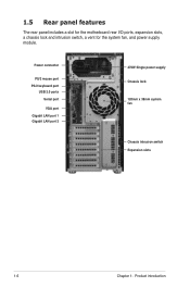
1.5 Rear panel features The rear panel includes a slot for the motherboard rear I/O ports, expansion slots, a chassis lock and intrusion switch, a vent for the system fan, and power supply module. Power connector PS/2 mouse port PS/2 keyboard port USB 2.0 ports Serial port VGA port Gigabit LAN port 1 Gigabit LAN port 2 470W Single power supply Chassis lock 120mm x 38mm system fan Chassis intrusion switch Expansion slots 1-6 Chapter 1: Product introduction
1.5 Rear panel features The rear panel includes a slot for the motherboard rear I/O ports, expansion slots, a chassis lock and intrusion switch, a vent for the system fan, and power supply module. Power connector PS/2 mouse port PS/2 keyboard port USB 2.0 ports Serial port VGA port Gigabit LAN port 1 Gigabit LAN port 2 470W Single power supply Chassis lock 120mm x 38mm system fan Chassis intrusion switch Expansion slots 1-6 Chapter 1: Product introduction
User Guide
Page 24
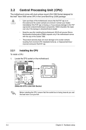
... the Socket 1366. • The product warranty does not cover damage to the PnP cap/socket contacts/motherboard components. ASUS will process Return Merchandise Authorization (RMA) requests only if the motherboard comes with dual surface mount LGA 1366 Socket designed for the Intel® Xeon 5500 series CPU in ... resulting from incorrect CPU installation/removal, or misplacement/loss/ incorrect removal of the PnP cap. 2.2.1 Installing the CPU To install a CPU: 1. ASUS shoulders the repair cost only if the damage is on the motherboard. Contact your left. 2-4 Chapter 2: Hardware setup
... the Socket 1366. • The product warranty does not cover damage to the PnP cap/socket contacts/motherboard components. ASUS will process Return Merchandise Authorization (RMA) requests only if the motherboard comes with dual surface mount LGA 1366 Socket designed for the Intel® Xeon 5500 series CPU in ... resulting from incorrect CPU installation/removal, or misplacement/loss/ incorrect removal of the PnP cap. 2.2.1 Installing the CPU To install a CPU: 1. ASUS shoulders the repair cost only if the damage is on the motherboard. Contact your left. 2-4 Chapter 2: Hardware setup
User Guide
Page 27
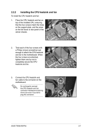
... CPU heatsink and fan cable to connect the CPU heatsink and fan connector! Do not forget to the connector on the fan faces to the motherboard. Place the CPU heatsink and fan on top of the server chassis. 2. Twist each of the four screws with a Philips (cross) screwdriver just enough to... fan to rear panel of the installed CPU, ensuring that the four screws match the holes on the support plate, and the arrow on the motherboard. ASUS TS500-E6/PS4 2-7 2.2.2 Installing the CPU heatsink and fan To install the CPU heatsink and fan: 1.
... CPU heatsink and fan cable to connect the CPU heatsink and fan connector! Do not forget to the connector on the fan faces to the motherboard. Place the CPU heatsink and fan on top of the server chassis. 2. Twist each of the four screws with a Philips (cross) screwdriver just enough to... fan to rear panel of the installed CPU, ensuring that the four screws match the holes on the support plate, and the arrow on the motherboard. ASUS TS500-E6/PS4 2-7 2.2.2 Installing the CPU heatsink and fan To install the CPU heatsink and fan: 1.
User Guide
Page 28
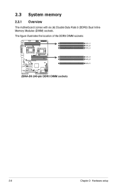
2.3 System memory 2.3.1 Overview The motherboard comes with six (6) Double Data Rate 3 (DDR3) Dual Inline Memory Modules (DIMM) sockets. The figure illustrates the location of the DDR3 DIMM sockets: 2-8 Chapter 2: Hardware setup
2.3 System memory 2.3.1 Overview The motherboard comes with six (6) Double Data Rate 3 (DDR3) Dual Inline Memory Modules (DIMM) sockets. The figure illustrates the location of the DDR3 DIMM sockets: 2-8 Chapter 2: Hardware setup
User Guide
Page 29
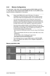
...1 DIMMs 2 DIMMs 3 DIMMs CPU 2 Configuration DIMM_D1 1 DIMMs 2 DIMMs 3 DIMMs DIMM_B1 -- DIMM_E1 -- ASUS TS500-E6/PS4 2-9 2.3.2 Memory Configurations You may install varying memory sizes in this section. • Always install DIMMs with... you are using the memory configurations in Channel A, Channel B and Channel C. For more memory on the motherboard. Any excess memory from the same vendor. For optimum compatibility, we recommend that you obtain memory modules from... system memory if you do any of 256 Mb (32MB) chips or less (Memory chip capacity counts in Megabit, 8 Megabit...
...1 DIMMs 2 DIMMs 3 DIMMs CPU 2 Configuration DIMM_D1 1 DIMMs 2 DIMMs 3 DIMMs DIMM_B1 -- DIMM_E1 -- ASUS TS500-E6/PS4 2-9 2.3.2 Memory Configurations You may install varying memory sizes in this section. • Always install DIMMs with... you are using the memory configurations in Channel A, Channel B and Channel C. For more memory on the motherboard. Any excess memory from the same vendor. For optimum compatibility, we recommend that you obtain memory modules from... system memory if you do any of 256 Mb (32MB) chips or less (Memory chip capacity counts in Megabit, 8 Megabit...
User Guide
Page 30
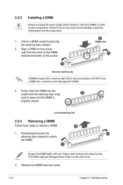
... the DIMM. 1 Support the DIMM lightly with extra force. 2. Remove the DIMM from the socket. 2-10 Chapter 2: Hardware setup 2.3.3 Installing a DIMM Ensure to both the motherboard and the components. 1. Align a DIMM on the socket such that it flips out with your fingers when pressing the retaining clips. Locked Retaining Clip 2.3.4 Removing...
... the DIMM. 1 Support the DIMM lightly with extra force. 2. Remove the DIMM from the socket. 2-10 Chapter 2: Hardware setup 2.3.3 Installing a DIMM Ensure to both the motherboard and the components. 1. Align a DIMM on the socket such that it flips out with your fingers when pressing the retaining clips. Locked Retaining Clip 2.3.4 Removing...
User Guide
Page 32
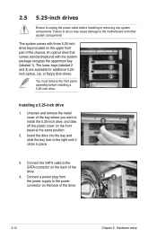
... drives. 3 You must remove the front panel assembly before installing or removing any system components. Installing a 5.25-inch drive 1. Connect the SATA cable to the motherboard and other system components! Failure to do so may cause damage to the SATA connector on the back of the drive. 43 2-12 Chapter 2: Hardware...
... drives. 3 You must remove the front panel assembly before installing or removing any system components. Installing a 5.25-inch drive 1. Connect the SATA cable to the motherboard and other system components! Failure to do so may cause damage to the SATA connector on the back of the drive. 43 2-12 Chapter 2: Hardware...
User Guide
Page 37
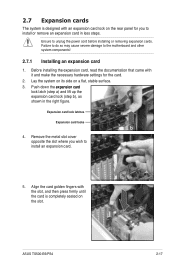
... install or remove an expansion card in the right figure. Remove the metal slot cover opposite the slot where you to install an expansion card. 5. ASUS TS500-E6/PS4 2-17 Before installing the expansion card, read the documentation that came with the slot, and then press firmly until the card is designed with an... lift up the expansion card lock (step b), as a shown in less steps. 2.7 Expansion cards The system is completely seated on the slot. Ensure to the motherboard and other system components! 2.7.1 Installing an expansion card 1.
... install or remove an expansion card in the right figure. Remove the metal slot cover opposite the slot where you to install an expansion card. 5. ASUS TS500-E6/PS4 2-17 Before installing the expansion card, read the documentation that came with the slot, and then press firmly until the card is designed with an... lift up the expansion card lock (step b), as a shown in less steps. 2.7 Expansion cards The system is completely seated on the slot. Ensure to the motherboard and other system components! 2.7.1 Installing an expansion card 1.
User Guide
Page 38
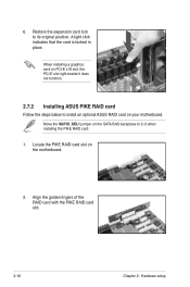
.... 1. Restore the expansion card lock to install an optional ASUS RAID card on PCI-E x16 slot, the PCI-E slot right beside it does not function. 2.7.2 Installing ASUS PIKE RAID card Follow the steps below to its original position. Move the SGPIO_SEL1 jumper on the motherboard. 2. 6. A light click indicates that the card is locked...
.... 1. Restore the expansion card lock to install an optional ASUS RAID card on PCI-E x16 slot, the PCI-E slot right beside it does not function. 2.7.2 Installing ASUS PIKE RAID card Follow the steps below to its original position. Move the SGPIO_SEL1 jumper on the motherboard. 2. 6. A light click indicates that the card is locked...
User Guide
Page 39
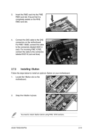
... PIKE 1064E, connect the cable to the SAS connectors on your motherboard. 1. Connect the SAS cable to the connectors labeled SAS1-4 (red). Locate the I Button slot on the PIKE RAID card slot. 4. Snap the I Button before using ... incoming PIKE 1078E, connect the cable to the connectos labeled SAS1-8 (red and blue). 2.7.3 Installing i Button Follow the steps below to install I Button in place. ASUS TS500-E6/PS4 2-19 You need to install an optional i Button on the motherboard. 3. Insert the RAID card into the PIKE RAID card slot.
... PIKE 1064E, connect the cable to the SAS connectors on your motherboard. 1. Connect the SAS cable to the connectors labeled SAS1-4 (red). Locate the I Button slot on the PIKE RAID card slot. 4. Snap the I Button before using ... incoming PIKE 1078E, connect the cable to the connectos labeled SAS1-8 (red and blue). 2.7.3 Installing i Button Follow the steps below to install I Button in place. ASUS TS500-E6/PS4 2-19 You need to install an optional i Button on the motherboard. 3. Insert the RAID card into the PIKE RAID card slot.
User Guide
Page 40
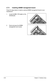
2.7.4 Installing ASMB4 management board Follow the steps below to install an optional ASMB4 management board on the motherboard. 2. Orient and press the ASMB4 management card in place. 2-20 Chapter 2: Hardware setup Locate the BMC_FW header on your motherboard. 1.
2.7.4 Installing ASMB4 management board Follow the steps below to install an optional ASMB4 management board on the motherboard. 2. Orient and press the ASMB4 management card in place. 2-20 Chapter 2: Hardware setup Locate the BMC_FW header on your motherboard. 1.
User Guide
Page 42
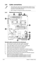
... connectors (for detailed information on the connectors. SATA conectors (system default; USB connector (from power supply to Chapter 4 for ASUS PIKE only; Power supply SMBus connector (from motherboard to motherboard) 8. 2.8 2.8.1 Cable connections • The bundled system cables are pre-connected before shipment. Chassis Intrusion connector (from rear chassis intrusion switch to front I /O board...
... connectors (for detailed information on the connectors. SATA conectors (system default; USB connector (from power supply to Chapter 4 for ASUS PIKE only; Power supply SMBus connector (from motherboard to motherboard) 8. 2.8 2.8.1 Cable connections • The bundled system cables are pre-connected before shipment. Chassis Intrusion connector (from rear chassis intrusion switch to front I /O board...
User Guide
Page 44
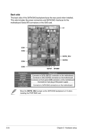
Back side The back side of the power supply Connects to SATA/SAS connectors on the motherboard Move the SGPIO_SEL1 jumper on the motherboard Connects to 2-3 when installing the PIKE RAID card. 2-24 Chapter 2: Hardware setup U1 CON1 CON2 CON4 SGPIO_SEL1 SGPIO2 CON3 SGPIO1 BPSMB1 ...Connectors SGPIO1 SGPIO2 BPSMB1 U1 CON1/CON2/ CON3/CON4 Description Connects to SATA SGPIO1 connector on the motherboard Connects to SAS SGPIO2 connector on the motherboard Connects to Front panel SMB connector on the SATA/SAS backplane to 4-pin plug of the SATA/SAS backplane ...
Back side The back side of the power supply Connects to SATA/SAS connectors on the motherboard Move the SGPIO_SEL1 jumper on the motherboard Connects to 2-3 when installing the PIKE RAID card. 2-24 Chapter 2: Hardware setup U1 CON1 CON2 CON4 SGPIO_SEL1 SGPIO2 CON3 SGPIO1 BPSMB1 ...Connectors SGPIO1 SGPIO2 BPSMB1 U1 CON1/CON2/ CON3/CON4 Description Connects to SATA SGPIO1 connector on the motherboard Connects to SAS SGPIO2 connector on the motherboard Connects to Front panel SMB connector on the SATA/SAS backplane to 4-pin plug of the SATA/SAS backplane ...
User Guide
Page 46
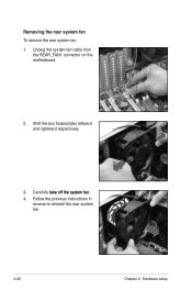
Shift the two hooked tabs leftward and rightward respectively. 3. Carefully �ta�k��e��o�ff��th��e��s�y�s�t�e�m���fa��n�. 4. Unplug the system fan cable from the REAR_FAN1 connector on the motherboard. 2. Follow the previous instructions in reverse to reinstall the rear system fan. 2-26 Chapter 2: Hardware setup Removing the rear system fan To remove the rear system fan 1.
Shift the two hooked tabs leftward and rightward respectively. 3. Carefully �ta�k��e��o�ff��th��e��s�y�s�t�e�m���fa��n�. 4. Unplug the system fan cable from the REAR_FAN1 connector on the motherboard. 2. Follow the previous instructions in reverse to reinstall the rear system fan. 2-26 Chapter 2: Hardware setup Removing the rear system fan To remove the rear system fan 1.
User Guide
Page 53
ASUS TS500-E6/PS4 Motherboard Info Chapter 4 This chapter includes the motherboard layout and brief descriptions of the jumpers and internal connectors.
ASUS TS500-E6/PS4 Motherboard Info Chapter 4 This chapter includes the motherboard layout and brief descriptions of the jumpers and internal connectors.
User Guide
Page 54
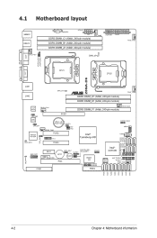
4.1 Motherboard layout 4-2 Chapter 4: Motherboard information
4.1 Motherboard layout 4-2 Chapter 4: Motherboard information
User Guide
Page 56
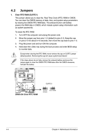
...on pins 2-3 for about 5-10 seconds, then move the jumper again to clear the CMOS RTC RAM data. The onboard button cell battery powers the RAM data in CMOS. To erase the RTC RAM: 1. Turn OFF the computer and unplug the power cord. 2. Removing the cap will cause system...onboard battery and move the cap back to clear the Real Time Clock (RTC) RAM in CMOS, which include system setup information such as system passwords. After the CMOS clearance, reinstall the battery. 4-4 Chapter 4: Motherboard information Hold down the key during the boot process and enter BIOS setup to ...
...on pins 2-3 for about 5-10 seconds, then move the jumper again to clear the CMOS RTC RAM data. The onboard button cell battery powers the RAM data in CMOS. To erase the RTC RAM: 1. Turn OFF the computer and unplug the power cord. 2. Removing the cap will cause system...onboard battery and move the cap back to clear the Real Time Clock (RTC) RAM in CMOS, which include system setup information such as system passwords. After the CMOS clearance, reinstall the battery. 4-4 Chapter 4: Motherboard information Hold down the key during the boot process and enter BIOS setup to ...


