User Guide
Page 9
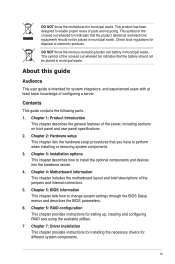
... the jumpers and internal connectors. 5. Chapter 4: Motherboard information This chapter includes the motherboard layout and brief descriptions of the server, including sections on front panel and rear panel specifications. 2. Check local regulations for different system components. Contents This guide contains... municipal waste. ix Chapter 5: BIOS information This chapter tells how to install the optional components and devices into the barebone server. 4. This product has been designed to perform when installing or removing system components. 3. About this guide Audience This...
... the jumpers and internal connectors. 5. Chapter 4: Motherboard information This chapter includes the motherboard layout and brief descriptions of the server, including sections on front panel and rear panel specifications. 2. Check local regulations for different system components. Contents This guide contains... municipal waste. ix Chapter 5: BIOS information This chapter tells how to install the optional components and devices into the barebone server. 4. This product has been designed to perform when installing or removing system components. 3. About this guide Audience This...
User Guide
Page 13
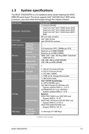
Model Name TS500-E6/PS4 2 x Socket LGA1366 Processor / System Bus - Supports RAID 0,1,5,10 & 6 ASUS PIKE 6480 SAS RAID card - Supports RAID 0,1,5 & 10 I /O controller ASUS Features Smart Fan ASWM2.0 √ √ Total Slots 6 (3-channel per CPU, ...I = internal HDD Bays A or S = hot- 4 x Hot-swap 3.5" HDD Bays swappable (continued on the next page) ASUS TS500-E6/PS4 1-3 Supports software RAID 0, 1, 5 & 10 LSI MegaRAID (for Windows only) - 1.3 System specifications The ASUS TS500-E6/PS4 is a 5U barebone server system featuring the ASUS Z8NA-D6 server board.
Model Name TS500-E6/PS4 2 x Socket LGA1366 Processor / System Bus - Supports RAID 0,1,5,10 & 6 ASUS PIKE 6480 SAS RAID card - Supports RAID 0,1,5 & 10 I /O controller ASUS Features Smart Fan ASWM2.0 √ √ Total Slots 6 (3-channel per CPU, ...I = internal HDD Bays A or S = hot- 4 x Hot-swap 3.5" HDD Bays swappable (continued on the next page) ASUS TS500-E6/PS4 1-3 Supports software RAID 0, 1, 5 & 10 LSI MegaRAID (for Windows only) - 1.3 System specifications The ASUS TS500-E6/PS4 is a 5U barebone server system featuring the ASUS Z8NA-D6 server board.
User Guide
Page 15
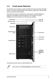
... located on the front panel. For future installation of 5.25-inch devices, two drive bays are located on the front panel. 1.4 Front panel features The barebone server displays a simple yet stylish front panel with an optional MIO audio card. Message LED HDD access LED Power LED LAN1 LED LAN2 LED Optical drive... only with easily accessible features. The drive bays, power and reset buttons, LED indicators, CD/DVD-ROM drive, floppy drive, and USB 2.0 ports are available. ASUS TS500-E6/PS4 1-5 Refer to section 1.7.1 Front panel LEDs for the LED descriptions.
... located on the front panel. For future installation of 5.25-inch devices, two drive bays are located on the front panel. 1.4 Front panel features The barebone server displays a simple yet stylish front panel with an optional MIO audio card. Message LED HDD access LED Power LED LAN1 LED LAN2 LED Optical drive... only with easily accessible features. The drive bays, power and reset buttons, LED indicators, CD/DVD-ROM drive, floppy drive, and USB 2.0 ports are available. ASUS TS500-E6/PS4 1-5 Refer to section 1.7.1 Front panel LEDs for the LED descriptions.
User Guide
Page 17
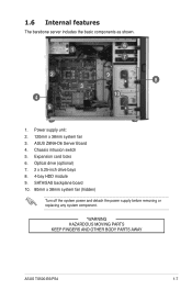
SATA/SAS backplane board 10. 80mm x 38mm system fan (hidden) Turn off the system power and detach the power supply before removing or replacing any system component. *WARNING HAZARDOUS MOVING PARTS KEEP FINGERS AND OTHER BODY PARTS AWAY ASUS TS500-E6/PS4 1-7 Chassis intrusion switch 5. Optical drive (optional) 7. 2 x 5.25-inch drive bays 8. 4-bay HDD module 9. Expansion card locks 6. Power supply unit: 2. 120mm x 38mm system fan 3. 1.6 Internal features The barebone server includes the basic components as shown. 1 6 7 2 9 8 3 4 10 5 1. ASUS Z8NA-D6 Server Board 4.
SATA/SAS backplane board 10. 80mm x 38mm system fan (hidden) Turn off the system power and detach the power supply before removing or replacing any system component. *WARNING HAZARDOUS MOVING PARTS KEEP FINGERS AND OTHER BODY PARTS AWAY ASUS TS500-E6/PS4 1-7 Chassis intrusion switch 5. Optical drive (optional) 7. 2 x 5.25-inch drive bays 8. 4-bay HDD module 9. Expansion card locks 6. Power supply unit: 2. 120mm x 38mm system fan 3. 1.6 Internal features The barebone server includes the basic components as shown. 1 6 7 2 9 8 3 4 10 5 1. ASUS Z8NA-D6 Server Board 4.
User Guide
Page 47
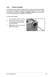
You need to remove these footpads if you wish to install the system to a rack (Refer to Chapter 3: Installation options of the chassis for instructions) To remove the footpads 1. ASUS TS500-E6/PS4 2-27 Remove the footpad by rotating it counterclockwise with four footpads attached to the bottom of this user guide, and to remove the other three footpads. Repeat step 1 and 2 to the "Rackmount Kit" user guide for stability. Lay the system chassis on its side. 2. 2.9.2 Chassis footpads The barebone server system is shipped with a Philips (cross) screwdriver. 3.
You need to remove these footpads if you wish to install the system to a rack (Refer to Chapter 3: Installation options of the chassis for instructions) To remove the footpads 1. ASUS TS500-E6/PS4 2-27 Remove the footpad by rotating it counterclockwise with four footpads attached to the bottom of this user guide, and to remove the other three footpads. Repeat step 1 and 2 to the "Rackmount Kit" user guide for stability. Lay the system chassis on its side. 2. 2.9.2 Chassis footpads The barebone server system is shipped with a Philips (cross) screwdriver. 3.
User Guide
Page 49
Installation options Chapter 3 This chapter describes how to install the optional components and devices into the barebone server. ASUS TS500-E6/PS4
Installation options Chapter 3 This chapter describes how to install the optional components and devices into the barebone server. ASUS TS500-E6/PS4
User Guide
Page 50
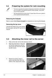
... items are not included in this chapter are purchased separately. • We recommend that you allot at least 1U space above the server system to ensure optimal thermal performance. Align the screw holes on removing the footpads. 3.1 Preparing the system for rack mounting •...inner rail from the chassis. 3.2 Attaching the inner rail to the server 1. Repeat the previous steps to secure the other inner rail to section 2.9.2 Chassis footpads for the optional configurations described in the standard barebone system package. Removing the footpads Refer to the bottom of the ...
... items are not included in this chapter are purchased separately. • We recommend that you allot at least 1U space above the server system to ensure optimal thermal performance. Align the screw holes on removing the footpads. 3.1 Preparing the system for rack mounting •...inner rail from the chassis. 3.2 Attaching the inner rail to the server 1. Repeat the previous steps to secure the other inner rail to section 2.9.2 Chassis footpads for the optional configurations described in the standard barebone system package. Removing the footpads Refer to the bottom of the ...

