User Manual
Page 11
Product introduction Chapter 1 This chapter describes the general features of the server, including sections on front panel and rear panel specifications. ASUS TS300-E6/PS4
Product introduction Chapter 1 This chapter describes the general features of the server, including sections on front panel and rear panel specifications. ASUS TS300-E6/PS4
User Manual
Page 13
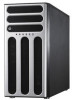
... Aspeed AST2050 8MB (continued on the next page) ASUS TS300-E6/PS4 1-3 Supports software RAID 0, 1, 5 & 10 Storage LSI MegaRAID (for Windows only) - 1.3 System specifications The ASUS TS300-E6/PS4 is a 5U barebone server system featuring the ASUS P7F-E server board. Supports software RAID 0, 1 & 10 ASUS PIKE 1064E 4-port SAS RAID card SAS Controller ASUS PIKE 1078 8-port SAS HW RAID card...
... Aspeed AST2050 8MB (continued on the next page) ASUS TS300-E6/PS4 1-3 Supports software RAID 0, 1, 5 & 10 Storage LSI MegaRAID (for Windows only) - 1.3 System specifications The ASUS TS300-E6/PS4 is a 5U barebone server system featuring the ASUS P7F-E server board. Supports software RAID 0, 1 & 10 ASUS PIKE 1064E 4-port SAS RAID card SAS Controller ASUS PIKE 1078 8-port SAS HW RAID card...
User Manual
Page 15
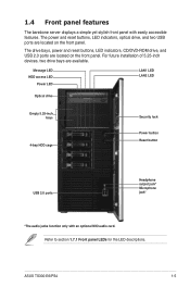
..., LED indicators, CD/DVD-ROM drive, and USB 2.0 ports are located on the front panel. Refer to section 1.7.1 Front panel LEDs for the LED descriptions. ASUS TS300-E6/PS4 1-5 Message LED HDD access LED Power LED LAN1 LED LAN2 LED Optical drive Empty 5.25-inch bays 4-bay HDD cage Security lock Power button Reset...
..., LED indicators, CD/DVD-ROM drive, and USB 2.0 ports are located on the front panel. Refer to section 1.7.1 Front panel LEDs for the LED descriptions. ASUS TS300-E6/PS4 1-5 Message LED HDD access LED Power LED LAN1 LED LAN2 LED Optical drive Empty 5.25-inch bays 4-bay HDD cage Security lock Power button Reset...
User Manual
Page 17
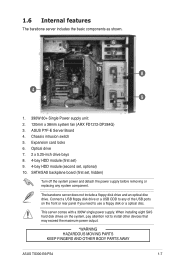
..., pay attention not to install other devices that may exceed the maximum power output. *WARNING HAZARDOUS MOVING PARTS KEEP FINGERS AND OTHER BODY PARTS AWAY ASUS TS300-E6/PS4 1-7 When installing eight SAS hard disk drives on the front or rear panel if you need to any system component. The barebone server does not.... 1.6 Internal features The barebone server includes the basic components as shown. 1 6 7 2 10 8 3 4 5 9 1. 390W 80+ Single Power supply unit: 2. 120mm x 38mm system fan (ARX FD1212-DP284G) 3. ASUS P7F-E Server Board 4.
..., pay attention not to install other devices that may exceed the maximum power output. *WARNING HAZARDOUS MOVING PARTS KEEP FINGERS AND OTHER BODY PARTS AWAY ASUS TS300-E6/PS4 1-7 When installing eight SAS hard disk drives on the front or rear panel if you need to any system component. The barebone server does not.... 1.6 Internal features The barebone server includes the basic components as shown. 1 6 7 2 10 8 3 4 5 9 1. 390W 80+ Single Power supply unit: 2. 120mm x 38mm system fan (ARX FD1212-DP284G) 3. ASUS P7F-E Server Board 4.

User Manual
Page 19
1.7.2 Rear panel LEDs ACT/LINK LED Status Description OFF No link GREEN Linked BLINKING Data activity ACT/LINK LED SPEED LED ACT/LINK LED SPEED LED SPEED LED Status Description OFF 10 Mbps connection ORANGE 100 Mbps connection GREEN 1 Gbps connection ASUS TS300-E6/PS4 1-9
1.7.2 Rear panel LEDs ACT/LINK LED Status Description OFF No link GREEN Linked BLINKING Data activity ACT/LINK LED SPEED LED ACT/LINK LED SPEED LED SPEED LED Status Description OFF 10 Mbps connection ORANGE 100 Mbps connection GREEN 1 Gbps connection ASUS TS300-E6/PS4 1-9
User Manual
Page 21
ASUS TS300-E6/PS4 Hardware setup Chapter 2 This chapter lists the hardware setup procedures that you have to perform when installing or removing system components.
ASUS TS300-E6/PS4 Hardware setup Chapter 2 This chapter lists the hardware setup procedures that you have to perform when installing or removing system components.
User Manual
Page 23
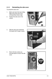
Position the side cover to secure the side cover. 4 ASUS TS300-E6/PS4 4 2-3 Drive in place. 1 3 4. 2.1.2 Reinstalling the side cover To reinstall the side cover 1. Slide the side cover toward the front panel until it snaps in the two screws you removed earlier to the chassis. 3. Match and insert the lower sliding edge of the side cover to the corresponding chassis edge. 2.
Position the side cover to secure the side cover. 4 ASUS TS300-E6/PS4 4 2-3 Drive in place. 1 3 4. 2.1.2 Reinstalling the side cover To reinstall the side cover 1. Slide the side cover toward the front panel until it snaps in the two screws you removed earlier to the chassis. 3. Match and insert the lower sliding edge of the side cover to the corresponding chassis edge. 2.
User Manual
Page 25
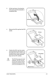
3. Lift the load lever in only one correct orientation. Load plate 4. Remove the PnP cap from the CPU socket. The CPU fits in the direction of the socket, and then fit the socket alignment keys into the socket to prevent bending the connectors on the bottom‑left corner of the arrow until the load plate is on the socket and damaging the CPU! DO NOT force the CPU into the CPU notches. Position the CPU over the socket, ensuring that the gold triangle is completely lifted. Gold triangle mark Alignment keys CPU notches ASUS TS300-E6/PS4 2-5 PnP cap 5.
3. Lift the load lever in only one correct orientation. Load plate 4. Remove the PnP cap from the CPU socket. The CPU fits in the direction of the socket, and then fit the socket alignment keys into the socket to prevent bending the connectors on the bottom‑left corner of the arrow until the load plate is on the socket and damaging the CPU! DO NOT force the CPU into the CPU notches. Position the CPU over the socket, ensuring that the gold triangle is completely lifted. Gold triangle mark Alignment keys CPU notches ASUS TS300-E6/PS4 2-5 PnP cap 5.
User Manual
Page 27
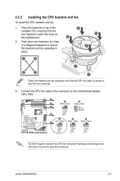
A B A A B 1 B A 1 Orient the heatsink and fan assembly such that the four fasteners match the holes on the motherboard labeled CPU_FAN. ASUS TS300-E6/PS4 2-7 2.2.2 Installing the CPU heatsink and fan To install the CPU heatsink and fan 1. Connect the CPU fan cable to the CPU fan connector. 3. Push down ...
A B A A B 1 B A 1 Orient the heatsink and fan assembly such that the four fasteners match the holes on the motherboard labeled CPU_FAN. ASUS TS300-E6/PS4 2-7 2.2.2 Installing the CPU heatsink and fan To install the CPU heatsink and fan 1. Connect the CPU fan cable to the CPU fan connector. 3. Push down ...
User Manual
Page 29
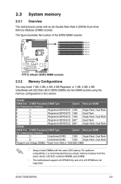
...; **Down from the same vendor. DO NOT combine RDIMM and UDIMM. • The motherboard supports x8 DRAM Only and x4 & x16 DRAM are not supported ASUS TS300-E6/PS4 2-9 2.3 System memory 2.3.1 Overview The motherboard comes with six (6) Double Data Rate 3 (DDR3) Dual Inline Memory Modules (DIMM) sockets. For optimum compatibility, it is recommended that...
...; **Down from the same vendor. DO NOT combine RDIMM and UDIMM. • The motherboard supports x8 DRAM Only and x4 & x16 DRAM are not supported ASUS TS300-E6/PS4 2-9 2.3 System memory 2.3.1 Overview The motherboard comes with six (6) Double Data Rate 3 (DDR3) Dual Inline Memory Modules (DIMM) sockets. For optimum compatibility, it is recommended that...
User Manual
Page 31
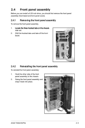
...; side rail. 2. Swing the front panel assembly and snap it back into place. Hook the other side of the front panel assembly to the chassis. 2. ASUS TS300-E6/PS4 2-11 Shift the hooked tabs and take off the front bezel. 2.4.2 Reinstalling the front panel assembly To reinstall the front panel assembly: 1.
...; side rail. 2. Swing the front panel assembly and snap it back into place. Hook the other side of the front panel assembly to the chassis. 2. ASUS TS300-E6/PS4 2-11 Shift the hooked tabs and take off the front bezel. 2.4.2 Reinstalling the front panel assembly To reinstall the front panel assembly: 1.
User Manual
Page 33
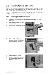
... properly. 6. Connect the appropriate cables to access the drive trays by simply opening the front bezel. Ensure of the type of wires and other obstructions. 2. ASUS TS300-E6/PS4 5 2-13 Insert the HDD module cage into the bay. 2 4.
... properly. 6. Connect the appropriate cables to access the drive trays by simply opening the front bezel. Ensure of the type of wires and other obstructions. 2. ASUS TS300-E6/PS4 5 2-13 Insert the HDD module cage into the bay. 2 4.

User Manual
Page 35
... the two 8 78 7 backplanes. 8. Connect eight SAS cables to pin 2-3. 10. Install a ASUS PIKE RAID card to the two J4 connectors on the two backplanes. 12. Refer to section 2.7.2 Installing ASUS PIKE RAID card for the exact locations of the SGPIO3 connector and section 2.8.2 SATA/SAS backplane connections... cable to the SGPIO3 connector on the motherboard. Connect two power supply cables to the SGPIO3 connector on the two backplanes. 9. ASUS TS300-E6/PS4 2-15 Connect the other ends of the SGPIO cable to the two U1 connectors on the first SAS backplane. 7.
... the two 8 78 7 backplanes. 8. Connect eight SAS cables to pin 2-3. 10. Install a ASUS PIKE RAID card to the two J4 connectors on the two backplanes. 12. Refer to section 2.7.2 Installing ASUS PIKE RAID card for the exact locations of the SGPIO3 connector and section 2.8.2 SATA/SAS backplane connections... cable to the SGPIO3 connector on the motherboard. Connect two power supply cables to the SGPIO3 connector on the two backplanes. 9. ASUS TS300-E6/PS4 2-15 Connect the other ends of the SGPIO cable to the two U1 connectors on the first SAS backplane. 7.
User Manual
Page 37
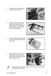
... insert the drive tray and push it with four screws. 5. Firmly hold the tray lever and pull the drive tray out of hard disk drives. ASUS TS300-E6/PS4 2-17 Each side has three holes to the SATAII/ SAS interface on the backplane.
... insert the drive tray and push it with four screws. 5. Firmly hold the tray lever and pull the drive tray out of hard disk drives. ASUS TS300-E6/PS4 2-17 Each side has three holes to the SATAII/ SAS interface on the backplane.
User Manual
Page 39
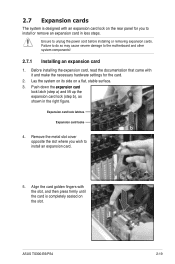
... on the slot. Expansion card lock latches Expansion card locks b 4. Remove the metal slot cover opposite the slot where you to install an expansion card. 5. ASUS TS300-E6/PS4 2-19 Failure to do so may cause severe damage to unplug the power cord before installing or removing expansion cards. Align the card golden fingers...
... on the slot. Expansion card lock latches Expansion card locks b 4. Remove the metal slot cover opposite the slot where you to install an expansion card. 5. ASUS TS300-E6/PS4 2-19 Failure to do so may cause severe damage to unplug the power cord before installing or removing expansion cards. Align the card golden fingers...

User Manual
Page 41
For PIKE 1064E, connect the cable to install an optional i Button on the motherboard. 2. ASUS TS300-E6/PS4 2-21 Snap the I Button slot on your motherboard. 1. Ensure that it is completely seated on the motherboard. For PIKE 1078 and 6480, connect the cable ...
For PIKE 1064E, connect the cable to install an optional i Button on the motherboard. 2. ASUS TS300-E6/PS4 2-21 Snap the I Button slot on your motherboard. 1. Ensure that it is completely seated on the motherboard. For PIKE 1078 and 6480, connect the cable ...
User Manual
Page 43
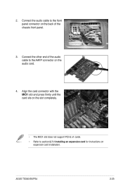
Connect the other end of the chassis front panel. 3. 2. Align the card connector with the MIO1 slot and press firmly until the card sits on the slot completely. • The MIO1 slot does not support PCI-E x1 cards. • Refer to the AAFP connector on the back of the audio cable to section 2.7.1 Installing an expansion card for instructions on expansion card installation. ASUS TS300-E6/PS4 2-23 Connect the audio cable to the front panel connector on the audio card. 4.
Connect the other end of the chassis front panel. 3. 2. Align the card connector with the MIO1 slot and press firmly until the card sits on the slot completely. • The MIO1 slot does not support PCI-E x1 cards. • Refer to the AAFP connector on the back of the audio cable to section 2.7.1 Installing an expansion card for instructions on expansion card installation. ASUS TS300-E6/PS4 2-23 Connect the audio cable to the front panel connector on the audio card. 4.
User Manual
Page 45
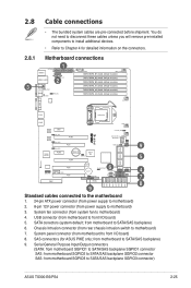
...need to disconnect these cables unless you will remove pre‑installed components to install additional devices. • Refer to Chapter 4 for ASUS PIKE only; System panel connector (from motherboard to front I /O board) 5. USB connector (from motherboard to front I /O board...SAS: from motherboard SGPIO2 to SATA/SAS backplane SGPIO2 connector SAS: from system fan to SATA/SAS backplane SGPIO3 connector) ASUS TS300-E6/PS4 2-25 System fan connector (from motherboard SGPIO3 to motherboard) 4. Chassis Intrusion connector (from motherboard to motherboard) 7. ...
...need to disconnect these cables unless you will remove pre‑installed components to install additional devices. • Refer to Chapter 4 for ASUS PIKE only; System panel connector (from motherboard to front I /O board) 5. USB connector (from motherboard to front I /O board...SAS: from motherboard SGPIO2 to SATA/SAS backplane SGPIO2 connector SAS: from system fan to SATA/SAS backplane SGPIO3 connector) ASUS TS300-E6/PS4 2-25 System fan connector (from motherboard SGPIO3 to motherboard) 4. Chassis Intrusion connector (from motherboard to motherboard) 7. ...
User Manual
Page 47
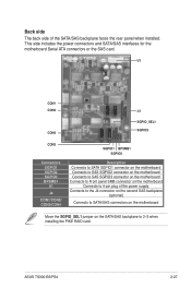
... Connects to Front panel SMB connector on the SATA/SAS backplane to 4-pin plug of the SATA/SAS backplane faces the rear panel when installed. ASUS TS300-E6/PS4 2-27
... Connects to Front panel SMB connector on the SATA/SAS backplane to 4-pin plug of the SATA/SAS backplane faces the rear panel when installed. ASUS TS300-E6/PS4 2-27

User Manual
Page 49
... on its side. 2. 3. You need to remove these footpads if you wish to install the system to a rack (Refer to remove the other three footpads. ASUS TS300-E6/PS4 2-29 Carefully �ta�k��e��o�ff��th��e��s�y�s�t�e�m��...
... on its side. 2. 3. You need to remove these footpads if you wish to install the system to a rack (Refer to remove the other three footpads. ASUS TS300-E6/PS4 2-29 Carefully �ta�k��e��o�ff��th��e��s�y�s�t�e�m��...


