
User Guide
Page 4
....1 Chassis fan 2-27 2.11.2 Floppy disk drive 2-29 2.11.3 Front I/O board 2-31 2.11.4 Power supply unit 2-33 Chapter 3: Motherboard info 3.1 Motherboard layouts 3-2 3.2 Jumpers 3-4 3.3 Connectors 3-9 3.3.1 Rear panel connectors 3-9 3.3.2 Internal connectors 3-10 Chapter 4: BIOS information 4.1 Managing and updating your BIOS 4-2 4.1.1 Creating a bootable floppy disk 4-2 4.1.2 AFUDOS utility 4-3 4.1.3 ASUS CrashFree BIOS 2 utility 4-5 4.1.4 ASUS Update utility 4-7 4.2 BIOS setup program 4-10 4.2.1 BIOS menu screen 4-11 4.2.2 Menu bar 4-11 4.2.3 Navigation keys 4-11 4.2.4 Menu...
....1 Chassis fan 2-27 2.11.2 Floppy disk drive 2-29 2.11.3 Front I/O board 2-31 2.11.4 Power supply unit 2-33 Chapter 3: Motherboard info 3.1 Motherboard layouts 3-2 3.2 Jumpers 3-4 3.3 Connectors 3-9 3.3.1 Rear panel connectors 3-9 3.3.2 Internal connectors 3-10 Chapter 4: BIOS information 4.1 Managing and updating your BIOS 4-2 4.1.1 Creating a bootable floppy disk 4-2 4.1.2 AFUDOS utility 4-3 4.1.3 ASUS CrashFree BIOS 2 utility 4-5 4.1.4 ASUS Update utility 4-7 4.2 BIOS setup program 4-10 4.2.1 BIOS menu screen 4-11 4.2.2 Menu bar 4-11 4.2.3 Navigation keys 4-11 4.2.4 Menu...

User Guide
Page 5
... CPU Configuration 4-21 4.4.5 Chipset Configuration 4-23 4.4.6 Onboard Devices Configuration 4-24 4.4.7 PCI/PnP Configuration 4-25 4.5 Power menu 4-26 4.5.1 APM Configuration 4-26 4.5.2 Hardware Monitor 4-28 4.6 Boot menu 4-30 4.6.1 Boot Device Priority 4-30 4.6.2 Boot Settings Configuration 4-31 4.6.3 Security 4-33 4.7 Exit menu 4-35 Chapter 5: RAID Configuration 5.1 Setting up RAID 5-2 5.1.1 RAID definitions 5-2 5.1.2 Installing hard disk drives 5-3 5.1.3 Setting the RAID item in BIOS 5-3 5.1.4 RAID configuration utilities 5-3 5.2 LSI Logic Embedded SATA RAID Setup Utility...
... CPU Configuration 4-21 4.4.5 Chipset Configuration 4-23 4.4.6 Onboard Devices Configuration 4-24 4.4.7 PCI/PnP Configuration 4-25 4.5 Power menu 4-26 4.5.1 APM Configuration 4-26 4.5.2 Hardware Monitor 4-28 4.6 Boot menu 4-30 4.6.1 Boot Device Priority 4-30 4.6.2 Boot Settings Configuration 4-31 4.6.3 Security 4-33 4.7 Exit menu 4-35 Chapter 5: RAID Configuration 5.1 Setting up RAID 5-2 5.1.1 RAID definitions 5-2 5.1.2 Installing hard disk drives 5-3 5.1.3 Setting the RAID item in BIOS 5-3 5.1.4 RAID configuration utilities 5-3 5.2 LSI Logic Embedded SATA RAID Setup Utility...

User Guide
Page 9
... experienced users with the server. Chapter 2: Hardware setup This chapter lists the hardware setup procedures that comes with at least basic knowledge of the server, including sections on front panel and rear panel specifications. 2. Chapter 3: Motherboard information This chapter gives information about the power supply unit and a troubleshooting guide for system components. Chapter 5: RAID configuration This chapter provides information on how to create a RAID set and how to change system settings through the BIOS Setup...
... experienced users with the server. Chapter 2: Hardware setup This chapter lists the hardware setup procedures that comes with at least basic knowledge of the server, including sections on front panel and rear panel specifications. 2. Chapter 3: Motherboard information This chapter gives information about the power supply unit and a troubleshooting guide for system components. Chapter 5: RAID configuration This chapter provides information on how to create a RAID set and how to change system settings through the BIOS Setup...
User Guide
Page 30
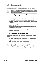
... shared slots, ensure that the drivers support "Shared IRQ" or that the cards do so may need IRQ assignments. Replace the system cover. 2.5.2 Configuring an expansion card After installing the expansion card, configure it and make the necessary hardware settings for the card. 2. Keep the screw for the expansion card. Failure to do not need to the chassis with the screw you intend to unplug the power cord before installing or removing expansion cards. Assign...
... shared slots, ensure that the drivers support "Shared IRQ" or that the cards do so may need IRQ assignments. Replace the system cover. 2.5.2 Configuring an expansion card After installing the expansion card, configure it and make the necessary hardware settings for the card. 2. Keep the screw for the expansion card. Failure to do not need to the chassis with the screw you intend to unplug the power cord before installing or removing expansion cards. Assign...

User Guide
Page 59
... in sleep mode. otherwise, the system would not power up. • If you to connect either a 3-pin or a 4-pin fan cable plug to wake up feature requires a power supply that can provide 500mA on the +5VSB lead for a 4-pin plug. 2 . CPU fan pin selection (3-pin FM_CPU1, FM_CPU2) These jumpers allow you are using Windows 2000, you need to install Service Pack 4 to the CPU fan connectors (CPU_FAN1, CPU_FAN2). ASUS TS100-E3 3-5
... in sleep mode. otherwise, the system would not power up. • If you to connect either a 3-pin or a 4-pin fan cable plug to wake up feature requires a power supply that can provide 500mA on the +5VSB lead for a 4-pin plug. 2 . CPU fan pin selection (3-pin FM_CPU1, FM_CPU2) These jumpers allow you are using Windows 2000, you need to install Service Pack 4 to the CPU fan connectors (CPU_FAN1, CPU_FAN2). ASUS TS100-E3 3-5

User Guide
Page 64
... PIN 1. 3-10 Chapter 3: Motherboard information P5MT-MX/C Floppy Disk Drive Connector 2 . P5MT-MX/C PIN 1 ® FLOPPY1 NOTE: Orient the red markings on the IDE ribbon cable to PIN 1. Refer to prevent incorrect cable connection when using a FDD cable with a covered Pin 5. 3.3.2 Internal connectors 1 . Pin 5 on the connector is removed to match the covered hole on the IDE connector is removed to the hard disk documentation for the jumper settings. • Pin 20...
... PIN 1. 3-10 Chapter 3: Motherboard information P5MT-MX/C Floppy Disk Drive Connector 2 . P5MT-MX/C PIN 1 ® FLOPPY1 NOTE: Orient the red markings on the IDE ribbon cable to PIN 1. Refer to prevent incorrect cable connection when using a FDD cable with a covered Pin 5. 3.3.2 Internal connectors 1 . Pin 5 on the connector is removed to match the covered hole on the IDE connector is removed to the hard disk documentation for the jumper settings. • Pin 20...

User Guide
Page 65
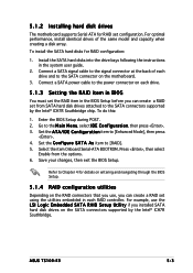
..., SATA4) These connectors are using the connectors in the BIOS to using Serial ATA hard disk drives. In I D E mode by default. 3. See section "4.3.4 IDE Configuration" for the recommended SATA hard disk drive connections. If you installed Serial ATA hard disk drives, you can create a RAID 0, RAID 1, RAID 0+1, and software RAID 5 configuration using the Intel® Matrix Storage Technology or RAID 0, RAID 1 and RAID 0+1 configuration using the LSI MegaRAID® utility embedded on Serial ATA • You must install Windows® 2000 Service Pack 4 or Windows® XP...
..., SATA4) These connectors are using the connectors in the BIOS to using Serial ATA hard disk drives. In I D E mode by default. 3. See section "4.3.4 IDE Configuration" for the recommended SATA hard disk drive connections. If you installed Serial ATA hard disk drives, you can create a RAID 0, RAID 1, RAID 0+1, and software RAID 5 configuration using the Intel® Matrix Storage Technology or RAID 0, RAID 1 and RAID 0+1 configuration using the LSI MegaRAID® utility embedded on Serial ATA • You must install Windows® 2000 Service Pack 4 or Windows® XP...

User Guide
Page 84
... of device connected to the system. Setting to [Auto] enables the LBA mode if the device supports this menu allow you to configure the item. Configuration options: [Disabled] [Auto] 4-14 Chapter 4: BIOS setup Main BIOS SETUP UTILITY Primary IDE Master Device : Hard Disk Vendor : HDS722516VLSA80 Size : 164.7GB LBA Mode : Supported Block Mode : 16 Sectors PIO Mode : Supported Async DMA : MultiWord DMA-2 Ultra DMA : Ultra DMA-5 SMART Monitoring: Supported Select the type of the appropriate IDE device type. The BIOS automatically detects...
... of device connected to the system. Setting to [Auto] enables the LBA mode if the device supports this menu allow you to configure the item. Configuration options: [Disabled] [Auto] 4-14 Chapter 4: BIOS setup Main BIOS SETUP UTILITY Primary IDE Master Device : Hard Disk Vendor : HDS722516VLSA80 Size : 164.7GB LBA Mode : Supported Block Mode : 16 Sectors PIO Mode : Supported Async DMA : MultiWord DMA-2 Ultra DMA : Ultra DMA-5 SMART Monitoring: Supported Select the type of the appropriate IDE device type. The BIOS automatically detects...

User Guide
Page 85
...] [RAID] ASUS TS100-E3 4-15 When set this item to [RAID] or [AHCI]. Configuration options: [Auto] [Disabled] [Enabled] 32Bit Data Transfer [Enabled] Enables or disables 32-bit data transfer. Select an item then press if you want to the device occurs multiple sectors at a time. Configuration options: [Disabled] [Auto] PIO Mode [Auto] Selects the PIO mode. Configure SATA as [Standard IDE] If you want the Serial ATA hard disk drives to use the Advanced Host Controller Interface (AHCI), set to...
...] [RAID] ASUS TS100-E3 4-15 When set this item to [RAID] or [AHCI]. Configuration options: [Auto] [Disabled] [Enabled] 32Bit Data Transfer [Enabled] Enables or disables 32-bit data transfer. Select an item then press if you want to the device occurs multiple sectors at a time. Configuration options: [Disabled] [Auto] PIO Mode [Auto] Selects the PIO mode. Configure SATA as [Standard IDE] If you want the Serial ATA hard disk drives to use the Advanced Host Controller Interface (AHCI), set to...

User Guide
Page 86
... Spinup Support. Suggest users to keep this item is set Serial ATA, Parallel ATA, or both, to enable or disable Serial-ATA bootrom function. Windows ME/98/NT, MS-DOS. When using native OS, e.g. Configuration options: [Disabled] [Enabled] AHCI Port3 Interlock Switch [Disabled] 4-16 Chapter 4: BIOS setup Configuration options: [Disabled] [Enabled] Onboard Serial-ATA BOOTROM and the sub-options will only show up only when Configure SATA As is set up when Configure SATA As...
... Spinup Support. Suggest users to keep this item is set Serial ATA, Parallel ATA, or both, to enable or disable Serial-ATA bootrom function. Windows ME/98/NT, MS-DOS. When using native OS, e.g. Configuration options: [Disabled] [Enabled] AHCI Port3 Interlock Switch [Disabled] 4-16 Chapter 4: BIOS setup Configuration options: [Disabled] [Enabled] Onboard Serial-ATA BOOTROM and the sub-options will only show up only when Configure SATA As is set up when Configure SATA As...

User Guide
Page 89
USB Function [8 USB Ports] Allows you to enable a specific number of legacy USB devices at startup. If detected, the USB controller legacy mode is disabled. Configuration options: [Disabled] [Enabled] [Auto] USB 2.0 Controller [Enabled] Allows you to enable or disable the USB 2.0 controller. Change Option F1 General Help F10 Save and Exit ESC Exit v02.58 (C)Copyright 1985-2004, American Megatrends, Inc. Configuration options: [1.1] [1.4] ASUS TS100-E3 4-19 Configuration options: [Disabled] [Enabled] 4.4.2 MPS Configuration Advanced MPS Configuration MPS Revision BIOS SETUP UTILITY...
USB Function [8 USB Ports] Allows you to enable a specific number of legacy USB devices at startup. If detected, the USB controller legacy mode is disabled. Configuration options: [Disabled] [Enabled] [Auto] USB 2.0 Controller [Enabled] Allows you to enable or disable the USB 2.0 controller. Change Option F1 General Help F10 Save and Exit ESC Exit v02.58 (C)Copyright 1985-2004, American Megatrends, Inc. Configuration options: [1.1] [1.4] ASUS TS100-E3 4-19 Configuration options: [Disabled] [Enabled] 4.4.2 MPS Configuration Advanced MPS Configuration MPS Revision BIOS SETUP UTILITY...

User Guide
Page 90
...UTF8 Combo Key Support under ANSI or VT-100. Configuration options: [Disabled] [Enabled] When [Remote Access] is [Always], some OS might not work. Configuration options: [115200 8, n, 1] [57600 8, n, 1] [38400 8, n, 1] [19200 8, n, 1] [09600 8, n, 1] Flow Control [None] Allows you to set up Serial port number [COM1] Allows you to enable or disable serial port. 4.4.3 Remote Access Configuration Advanced BIOS SETUP UTILITY Configure Remote Access type and parameters Remote Access [Disabled] Select Remote Access type. Configuration options: [None] [Hardware] [Software] v02.58...
...UTF8 Combo Key Support under ANSI or VT-100. Configuration options: [Disabled] [Enabled] When [Remote Access] is [Always], some OS might not work. Configuration options: [115200 8, n, 1] [57600 8, n, 1] [38400 8, n, 1] [19200 8, n, 1] [09600 8, n, 1] Flow Control [None] Allows you to set up Serial port number [COM1] Allows you to enable or disable serial port. 4.4.3 Remote Access Configuration Advanced BIOS SETUP UTILITY Configure Remote Access type and parameters Remote Access [Disabled] Select Remote Access type. Configuration options: [None] [Hardware] [Software] v02.58...
User Guide
Page 96
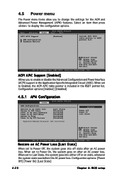
... v02.58 (C)Copyright 1985-2004, American Megatrends, Inc. Configuration options: [Power Off] [Power On] [Last State] 4-26 Chapter 4: BIOS setup Main Advanced Power ACPI APIC Support APM Configuration Hardware Monitor BIOS SETUP UTILITY Boot Exit [Enabled] Include ACPI APIC table pointer to display the configuration options. ACPI APIC Support [Enabled] Allows you to change the settings for the ACPI and Advanced Power Management (APM) features. Change Option F1 General Help F10 Save and Exit...
... v02.58 (C)Copyright 1985-2004, American Megatrends, Inc. Configuration options: [Power Off] [Power On] [Last State] 4-26 Chapter 4: BIOS setup Main Advanced Power ACPI APIC Support APM Configuration Hardware Monitor BIOS SETUP UTILITY Boot Exit [Enabled] Include ACPI APIC table pointer to display the configuration options. ACPI APIC Support [Enabled] Allows you to change the settings for the ACPI and Advanced Power Management (APM) features. Change Option F1 General Help F10 Save and Exit...

User Guide
Page 101
... select the power-on self tests (POST) while booting to decrease the time needed to use the ASUS MyLogo™ feature. 4.6.2 Boot Settings Configuration BIOS SETUP UTILITY Boot Boot Settings Configuration Quick Boot Full Screen Logo Add On ROM Display Mode Bootup Num-Lock PS/2 Mouse Support Wait For 'F1' If Error Hit 'DEL' Message Display Interrupt 19 Capture [Enabled] [Enabled] [Force BIOS] [On] [Auto] [Enabled] [Enabled] [Disabled] Allows BIOS to boot the system. Select Screen Select Item +- Configuration options: [Enabled][Disabled] AddOn ROM Display Mode [Force BIOS] Allows...
... select the power-on self tests (POST) while booting to decrease the time needed to use the ASUS MyLogo™ feature. 4.6.2 Boot Settings Configuration BIOS SETUP UTILITY Boot Boot Settings Configuration Quick Boot Full Screen Logo Add On ROM Display Mode Bootup Num-Lock PS/2 Mouse Support Wait For 'F1' If Error Hit 'DEL' Message Display Interrupt 19 Capture [Enabled] [Enabled] [Force BIOS] [On] [Auto] [Enabled] [Enabled] [Disabled] Allows BIOS to boot the system. Select Screen Select Item +- Configuration options: [Enabled][Disabled] AddOn ROM Display Mode [Force BIOS] Allows...
User Guide
Page 103
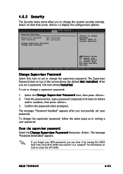
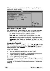
... disable password. ASUS TS100-E3 4-33 Clear the supervisor password: Select the Change Supervisor Password then press . The message "Password Uninstalled" appears. To set your BIOS password, you can clear it by erasing the CMOS Real Time Clock (RTC) RAM. Confirm the password when prompted. If you forget your password. 4.6.3 Security The Security menu items allow you to display the configuration options. From the password box, type a password composed of the screen shows the default...
... disable password. ASUS TS100-E3 4-33 Clear the supervisor password: Select the Change Supervisor Password then press . The message "Password Uninstalled" appears. To set your BIOS password, you can clear it by erasing the CMOS Real Time Clock (RTC) RAM. Confirm the password when prompted. If you forget your password. 4.6.3 Security The Security menu items allow you to display the configuration options. From the password box, type a password composed of the screen shows the default...
User Guide
Page 104
... six letters and/or numbers, then press . 3. To set or change other items appear to the Setup utility. BIOS SETUP UTILITY Boot Security Settings Supervisor Password : Installed User Password : Not Installed Change Supervisor Password User Access Level Change User Password Clear User Password Password Check [Full Access] [Setup] Select Screen Select Item +- After you to any field. Confirm the password when prompted. Change User Password Select this item shows I n s t a l l e d. On the password box that appears, type a password composed of the screen shows the default...
... six letters and/or numbers, then press . 3. To set or change other items appear to the Setup utility. BIOS SETUP UTILITY Boot Security Settings Supervisor Password : Installed User Password : Not Installed Change Supervisor Password User Access Level Change User Password Clear User Password Password Check [Full Access] [Setup] Select Screen Select Item +- After you to any field. Confirm the password when prompted. Change User Password Select this item shows I n s t a l l e d. On the password box that appears, type a password composed of the screen shows the default...

User Guide
Page 108
... configuration stores the same data redundantly on the operating system. If you install an operating system to hard disk drives that are not yet configured as a RAID set , copy first the RAID driver from one drive fails, the disk array management software directs all applications to a second drive. Use two new drives or use an existing drive and a new drive for this setup. 5.1 Setting up RAID The motherboard comes with the following RAID solutions: P5MT-MX/C model • LSI Logic Embedded SATA RAID...
... configuration stores the same data redundantly on the operating system. If you install an operating system to hard disk drives that are not yet configured as a RAID set , copy first the RAID driver from one drive fails, the disk array management software directs all applications to a second drive. Use two new drives or use an existing drive and a new drive for this setup. 5.1 Setting up RAID The motherboard comes with the following RAID solutions: P5MT-MX/C model • LSI Logic Embedded SATA RAID...
User Guide
Page 109
... a RAID set using the utilities embedded in each drive. 5.1.3 Setting the RAID item in BIOS You must set configuration. For example, use , you can create a RAID set from the options. 6. Go to the power connector on the motherboard. 3. Refer to the signal connector at the back of the same model and capacity when creating a disk array. ASUS TS100-E3 5-3 Set the ATA/IDE Configuration item to [RAID]. 5. Enter the BIOS Setup during POST. 2. Save your changes, then exit the BIOS Setup. Connect a SATA signal cable...
... a RAID set using the utilities embedded in each drive. 5.1.3 Setting the RAID item in BIOS You must set configuration. For example, use , you can create a RAID set from the options. 6. Go to the power connector on the motherboard. 3. Refer to the signal connector at the back of the same model and capacity when creating a disk array. ASUS TS100-E3 5-3 Set the ATA/IDE Configuration item to [RAID]. 5. Enter the BIOS Setup during POST. 2. Save your changes, then exit the BIOS Setup. Connect a SATA signal cable...
User Guide
Page 147
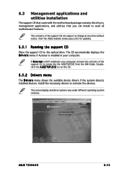
... versions. 6.3 Management applications and utilities installation The support CD that came with the motherboard package contains the drivers, management applications, and utilities that you can install to run the CD. 6.3.2 Drivers menu The D r i v e r s menu shows the available device drivers if the system detects installed devices. The contents of the support CD to change at any time without notice. E X E to avail all motherboard features. Doubleclick the A S S E T U P . ASUS TS100-E3 6-15 Visit the ASUS website (www.asus.com) for updates. 6.3.1 Running...
... versions. 6.3 Management applications and utilities installation The support CD that came with the motherboard package contains the drivers, management applications, and utilities that you can install to run the CD. 6.3.2 Drivers menu The D r i v e r s menu shows the available device drivers if the system detects installed devices. The contents of the support CD to change at any time without notice. E X E to avail all motherboard features. Doubleclick the A S S E T U P . ASUS TS100-E3 6-15 Visit the ASUS website (www.asus.com) for updates. 6.3.1 Running...
User Guide
Page 152
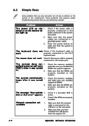
... the power cable is properly connected to the mouse port. Make sure that the power cables are properly installed on 2. T h e m o u s e d o e s n o t w o r k Check if the mouse cable is properly connected to a grounded power outlet. T h e s y s t e m d o e s n o t 1. perform power-on self tests (POST) after it was turned on the sockets. T h e s y s t e m c o n t i n u o u s l y 1. Check the memory modules and make sure you have installed the LAN drivers from the support CD. Make sure that the DIMMs are connected to the power connector in the system rear panel...
... the power cable is properly connected to the mouse port. Make sure that the power cables are properly installed on 2. T h e m o u s e d o e s n o t w o r k Check if the mouse cable is properly connected to a grounded power outlet. T h e s y s t e m d o e s n o t 1. perform power-on self tests (POST) after it was turned on the sockets. T h e s y s t e m c o n t i n u o u s l y 1. Check the memory modules and make sure you have installed the LAN drivers from the support CD. Make sure that the DIMMs are connected to the power connector in the system rear panel...


