User Manual
Page 13
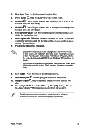
...Digital™/MultimediaCard/Memory Stick storage card. For Windows® Vista system, enable AHCI mode from or writing to eject the optical drive. 9. ASUS T-P5G43 1-3 This is reading from slowing down. 8. This Mic (pink) port connects a microphone. 10. Press this button to the hard disk drive... Silver Bezel) 5. These Universal Serial Bus 2.0 (USB 2.0) ports are available for connecting USB 2.0 devices such as a general guide for Black Bezel) 4. Refer to open the front panel cover and display the input/output ports. 6. For Windows® XP system, refer to the...
...Digital™/MultimediaCard/Memory Stick storage card. For Windows® Vista system, enable AHCI mode from or writing to eject the optical drive. 9. ASUS T-P5G43 1-3 This is reading from slowing down. 8. This Mic (pink) port connects a microphone. 10. Press this button to the hard disk drive... Silver Bezel) 5. These Universal Serial Bus 2.0 (USB 2.0) ports are available for connecting USB 2.0 devices such as a general guide for Black Bezel) 4. Refer to open the front panel cover and display the input/output ports. 6. For Windows® XP system, refer to the...
User Manual
Page 16
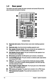
... port connects the rear speakers on a 4-channel, 6-channel, or 8-channel audio configuration. 15. HDMI port. This Microphone port connects a microphone. 17. Rear speaker Out port (black). This green 6-pin connector is for a VGA monitor or other protected content. 19. This 15-pin port is for a High-Definition Multimedia Interface (HDMI) connector... playback of devices. 24 12 25 13 26 14 15 27 16 28 17 18 19 29 20 30 21 31 22 32 23 33 T3-P5G43/T4-P5G43 12. PS/2 mouse port (green). Side Speaker Out port (gray).
... port connects the rear speakers on a 4-channel, 6-channel, or 8-channel audio configuration. 15. HDMI port. This Microphone port connects a microphone. 17. Rear speaker Out port (black). This green 6-pin connector is for a VGA monitor or other protected content. 19. This 15-pin port is for a High-Definition Multimedia Interface (HDMI) connector... playback of devices. 24 12 25 13 26 14 15 27 16 28 17 18 19 29 20 30 21 31 22 32 23 33 T3-P5G43/T4-P5G43 12. PS/2 mouse port (green). Side Speaker Out port (gray).
User Manual
Page 59
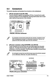
... EATXPWR PIN 1 +3 Volts +3 Volts GND +5 Volts GND +5 Volts GND Power OK +5V Standby +12 Volts +12 Volts +3 Volts P5Q18L P5Q18L ATX power connectors ASUS T-P5G43 +3 Volts -12 Volts GND PSON# GND GND GND -5 Volts +5 Volts +5 Volts +5 Volts GND ATX12V +12V DC +12V DC PIN 1 GND GND 4-5 ATX...from the power supply unit are not jumpers! 4.4 Connectors This section describes and illustrates the connectors on the motherboard, ensuring that the black wire of each cable matches the ground pin of the connector. Otherwise, the system will not boot up. Find the proper orientation ...
... EATXPWR PIN 1 +3 Volts +3 Volts GND +5 Volts GND +5 Volts GND Power OK +5V Standby +12 Volts +12 Volts +3 Volts P5Q18L P5Q18L ATX power connectors ASUS T-P5G43 +3 Volts -12 Volts GND PSON# GND GND GND -5 Volts +5 Volts +5 Volts +5 Volts GND ATX12V +12V DC +12V DC PIN 1 GND GND 4-5 ATX...from the power supply unit are not jumpers! 4.4 Connectors This section describes and illustrates the connectors on the motherboard, ensuring that the black wire of each cable matches the ground pin of the connector. Otherwise, the system will not boot up. Find the proper orientation ...
User Manual
Page 61
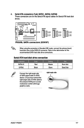
... in Standard IDE mode, connect the primary (boot) hard disk drive to SATA device. Serial ATA hard disk drive connection Connector SATA1/3 SATA2 Color Red Black Setting Master Slave Use Boot disk Data Disk Connect the right-angle side of SATA cable to the onboard SATA port to the table below...
... in Standard IDE mode, connect the primary (boot) hard disk drive to SATA device. Serial ATA hard disk drive connection Connector SATA1/3 SATA2 Color Red Black Setting Master Slave Use Boot disk Data Disk Connect the right-angle side of SATA cable to the onboard SATA port to the table below...