User Manual
Page 8
... install drivers and utilities from the support CD. 4. The chapter lists the system features, including introduction on how to change system settings through the BIOS Setup menus and describes the BIOS parameters. 6. Appendix The Appendix includes the power supply unit specification, remote control for experienced users and integrators with the system. This chapter includes the motherboard layout, jumper settings, and connector locations. 5. Chapter 4: Motherboard info This chapter gives information about ASUS T-P5G43 barebone system. Chapter 5: BIOS...
... install drivers and utilities from the support CD. 4. The chapter lists the system features, including introduction on how to change system settings through the BIOS Setup menus and describes the BIOS parameters. 6. Appendix The Appendix includes the power supply unit specification, remote control for experienced users and integrators with the system. This chapter includes the motherboard layout, jumper settings, and connector locations. 5. Chapter 4: Motherboard info This chapter gives information about ASUS T-P5G43 barebone system. Chapter 5: BIOS...
User Manual
Page 12
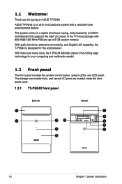
... home entertainment feature. The storage card reader slots, and several I/O ports are located inside the front panel cover. 1.2.1 T3-P5G43 front panel External 1 2 Internal 7 8 3 6 9 10 4 11 5 1-2 Chapter 1: System introduction The system comes in a stylish mini-tower casing, and powered by an ASUS motherboard that supports the Intel® processor in -one barebone system with 800/1066/1333 MHz FSB and up to 8 GB system memory. With these and many more...
... home entertainment feature. The storage card reader slots, and several I/O ports are located inside the front panel cover. 1.2.1 T3-P5G43 front panel External 1 2 Internal 7 8 3 6 9 10 4 11 5 1-2 Chapter 1: System introduction The system comes in a stylish mini-tower casing, and powered by an ASUS motherboard that supports the Intel® processor in -one barebone system with 800/1066/1333 MHz FSB and up to 8 GB system memory. With these and many more...
User Manual
Page 13
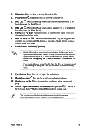
Drive door. Power button . HDD LED . HDD LED . This LED lights up when data is reading from or writing to the hard disk drive. (for connecting USB 2.0 devices such as a general guide for a Secure Digital™/MultimediaCard/Memory Stick storage card. Front panel I/O cover. Microphone port . This Mic (pink) port connects a microphone. 10. ASUS T-P5G43 1-3 Open this button to Windows® XP installation for details. These Universal Serial Bus 2.0 (USB 2.0) ports are available for Silver Bezel) 5. For Windows® XP system, refer to the...
Drive door. Power button . HDD LED . HDD LED . This LED lights up when data is reading from or writing to the hard disk drive. (for connecting USB 2.0 devices such as a general guide for a Secure Digital™/MultimediaCard/Memory Stick storage card. Front panel I/O cover. Microphone port . This Mic (pink) port connects a microphone. 10. ASUS T-P5G43 1-3 Open this button to Windows® XP installation for details. These Universal Serial Bus 2.0 (USB 2.0) ports are available for Silver Bezel) 5. For Windows® XP system, refer to the...
User Manual
Page 15
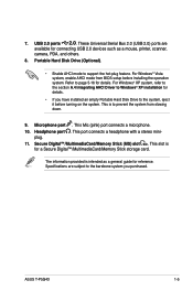
... Windows® Vista system, enable AHCI mode from slowing down. 9. This Mic (pink) port connects a microphone. 10. Secure Digital™/MultimediaCard/Memory Stick (MS) slot . ASUS T-P5G43 1-5 Refer to the barebone system you have installed an empty Portable Hard Disk Drive to support the hot-plug feature. 7. Specifications are available for connecting USB 2.0 devices such as a general guide for details. Portable Hard Disk Drive (Optional). • Enable AHCI mode to the system, eject it before installing the operation system. plug...
... Windows® Vista system, enable AHCI mode from slowing down. 9. This Mic (pink) port connects a microphone. 10. Secure Digital™/MultimediaCard/Memory Stick (MS) slot . ASUS T-P5G43 1-5 Refer to the barebone system you have installed an empty Portable Hard Disk Drive to support the hot-plug feature. 7. Specifications are available for connecting USB 2.0 devices such as a general guide for details. Portable Hard Disk Drive (Optional). • Enable AHCI mode to the system, eject it before installing the operation system. plug...
User Manual
Page 16
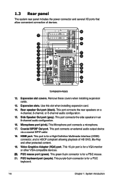
...(HDMI) connector, and is for a PS/2 mouse. 21. 1.3 Rear panel The system rear panel includes the power connector and several I/O ports that allow convenient connection of HD DVD, Blu-Ray and other VGA-compatible devices. 20. This Microphone port connects a microphone. 17. HDMI port. PS/2 mouse port (green). Microphone port (pink). Rear speaker Out port (black). Coaxial S/PDIF Out port. Video Graphics Adapter (VGA) port. Remove these covers when installing expansion cards. 13. This port connects the side speakers in an 8-channel audio configuration. 16. This purple 6-pin...
...(HDMI) connector, and is for a PS/2 mouse. 21. 1.3 Rear panel The system rear panel includes the power connector and several I/O ports that allow convenient connection of HD DVD, Blu-Ray and other VGA-compatible devices. 20. This Microphone port connects a microphone. 17. HDMI port. PS/2 mouse port (green). Microphone port (pink). Rear speaker Out port (black). Coaxial S/PDIF Out port. Video Graphics Adapter (VGA) port. Remove these covers when installing expansion cards. 13. This port connects the side speakers in an 8-channel audio configuration. 16. This purple 6-pin...

User Manual
Page 17
... devices. 33. Power switch. ASUS T-P5G43 1-7 This vent is for connecting USB 2.0 devices such as a mouse, printer, scanner, camera, PDA, and others. 24. See page 2-14 for the fan that provides ventilation inside the system chassis. 25. Line In port (light blue). This connector is for details. 26. In 4/6-channel mode, the function of this port becomes Front Speaker Out. 29. This port allows connection to an external Serial ATA hard disk drive. Center & woofer speakers...
... devices. 33. Power switch. ASUS T-P5G43 1-7 This vent is for connecting USB 2.0 devices such as a mouse, printer, scanner, camera, PDA, and others. 24. See page 2-14 for the fan that provides ventilation inside the system chassis. 25. Line In port (light blue). This connector is for details. 26. In 4/6-channel mode, the function of this port becomes Front Speaker Out. 29. This port allows connection to an external Serial ATA hard disk drive. Center & woofer speakers...
User Manual
Page 36
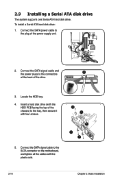
2.9 Installing a Serial ATA disk drive The system supports one Serial ATA hard disk drive. Insert a hard disk drive (with the HDD PCB facing the top of the drive. 3. Locate the HDD tray. 4. To install a Serial ATA hard disk drive: 1. Connect the SATA signal cable and the power plugs to the connectors 2 at the back of the chassis) to the tray, then secure it with the plastic coils. 4 4 4 4 4 2-16 Chapter 2: Basic installation Connect the SATA power cable to the SATA connector on the motherboard, and tighten all...
2.9 Installing a Serial ATA disk drive The system supports one Serial ATA hard disk drive. Insert a hard disk drive (with the HDD PCB facing the top of the drive. 3. Locate the HDD tray. 4. To install a Serial ATA hard disk drive: 1. Connect the SATA signal cable and the power plugs to the connectors 2 at the back of the chassis) to the tray, then secure it with the plastic coils. 4 4 4 4 4 2-16 Chapter 2: Basic installation Connect the SATA power cable to the SATA connector on the motherboard, and tighten all...
User Manual
Page 41
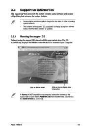
.... Click an item to install Click an icon to locate the file ASSETUP.EXE from the BIN folder. 3.3 Support CD information The support CD that came with the system contains useful software and several utility drivers that enhance the system features. • Screen display and driver options may not be the same for updates. 3.3.1 Running the support CD To begin using the support CD, place the CD...
.... Click an item to install Click an icon to locate the file ASSETUP.EXE from the BIN folder. 3.3 Support CD information The support CD that came with the system contains useful software and several utility drivers that enhance the system features. • Screen display and driver options may not be the same for updates. 3.3.1 Running the support CD To begin using the support CD, place the CD...

User Manual
Page 48
... system will open a particular configuration tool. If you click Restore System, a confirmation dialog box will immediately restart and then re-enter Express Gate to the Internet. Click on your computer connects to finish clearing the settings. After you click "Yes" in the rare case where settings might become corrupted. The user data will run again when you to open . For PPPoE and wireless (optional), set current...
... system will open a particular configuration tool. If you click Restore System, a confirmation dialog box will immediately restart and then re-enter Express Gate to the Internet. Click on your computer connects to finish clearing the settings. After you click "Yes" in the rare case where settings might become corrupted. The user data will run again when you to open . For PPPoE and wireless (optional), set current...
User Manual
Page 51
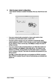
... enter the username and password for your computer to your DSL/cable modem (no router in between), click Setup for any LAN port. If this is not the case, click Setup to configure the static IP settings manually. • If you don't need to as PPPoE. Click OK to your computer's LAN port. If this is the case, you use a network cable connected to a home router (which is then connected...
... enter the username and password for your computer to your DSL/cable modem (no router in between), click Setup for any LAN port. If this is not the case, click Setup to configure the static IP settings manually. • If you don't need to as PPPoE. Click OK to your computer's LAN port. If this is the case, you use a network cable connected to a home router (which is then connected...
User Manual
Page 53
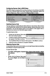
Main Advanced BIOS SETUP UTILITY Power Boot Tools Exit ASUS EZ Flash 2 Express Gate Enter OS Timer Reset User Data [Enabled] [10 Seconds] [No] Press ENTER to run the utility to complete installation. New versions of the software on the support DVD or download new versions from the ASUS support website. You can repair Express Gate by clicking on the BIOS setup icon on Express Gate's first screen. Repairing Express Gate In case Express Gate cannot start software update. 2. Express Gate configuration options are under...
Main Advanced BIOS SETUP UTILITY Power Boot Tools Exit ASUS EZ Flash 2 Express Gate Enter OS Timer Reset User Data [Enabled] [10 Seconds] [No] Press ENTER to run the utility to complete installation. New versions of the software on the support DVD or download new versions from the ASUS support website. You can repair Express Gate by clicking on the BIOS setup icon on Express Gate's first screen. Repairing Express Gate In case Express Gate cannot start software update. 2. Express Gate configuration options are under...
User Manual
Page 64
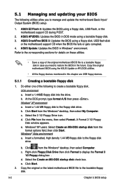
... format options field, then click Start. d. ASUS CrashFree BIOS 3: Updates the BIOS using a floppy disk, USB Flash, or the motherboard support CD during POST. 2. Do either one of the original motherboard BIOS file to a bootable floppy disk in case you to manage and update the motherboard Basic Input/ Output System (BIOS) setup. 1. Insert a 1.44MB floppy disk into the drive. At the DOS prompt, type format A:/S then press . Select the 3 1/2 Floppy Drive icon. d. Windows® XP users: Select...
... format options field, then click Start. d. ASUS CrashFree BIOS 3: Updates the BIOS using a floppy disk, USB Flash, or the motherboard support CD during POST. 2. Do either one of the original motherboard BIOS file to a bootable floppy disk in case you to manage and update the motherboard Basic Input/ Output System (BIOS) setup. 1. Insert a 1.44MB floppy disk into the drive. At the DOS prompt, type format A:/S then press . Select the 3 1/2 Floppy Drive icon. d. Windows® XP users: Select...
User Manual
Page 68
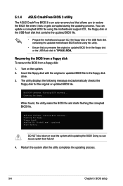
... motherboard support CD, the floppy disk or the USB flash disk containing the updated motherboard BIOS before using this utility. • Ensure that allows you rename the original or updated BIOS file in the floppy disk or the USB flash disk to T-P5G43.ROM. Checking for floppy... Completed. Recovering the BIOS from a floppy disk To recover the BIOS from a floppy disk: 1. Restart the system after the utility completes the updating process. 5-6 Chapter 5: BIOS setup Turn on the system. 2. 5.1.4 ASUS...
... motherboard support CD, the floppy disk or the USB flash disk containing the updated motherboard BIOS before using this utility. • Ensure that allows you rename the original or updated BIOS file in the floppy disk or the USB flash disk to T-P5G43.ROM. Checking for floppy... Completed. Recovering the BIOS from a floppy disk To recover the BIOS from a floppy disk: 1. Restart the system after the utility completes the updating process. 5-6 Chapter 5: BIOS setup Turn on the system. 2. 5.1.4 ASUS...
User Manual
Page 70
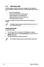
... connection either through a network or an Internet Service Provider (ISP). The Drivers menu appears. 2. 5.1.5 ASUS Update utility The ASUS Update is available in the support CD that allows you to manage, save, and update the motherboard BIOS in the optical drive. This utility is a utility that comes with the motherboard package. See page 3-5 for the Utilities screen menu. 3. Click the Utilities tab, then click Install ASUS Update. Installing ASUS Update To install ASUS Update: 1. The ASUS Update utility allows you update the BIOS using this utility. 5-8 Chapter 5: BIOS setup...
... connection either through a network or an Internet Service Provider (ISP). The Drivers menu appears. 2. 5.1.5 ASUS Update utility The ASUS Update is available in the support CD that allows you to manage, save, and update the motherboard BIOS in the optical drive. This utility is a utility that comes with the motherboard package. See page 3-5 for the Utilities screen menu. 3. Click the Utilities tab, then click Install ASUS Update. Installing ASUS Update To install ASUS Update: 1. The ASUS Update utility allows you update the BIOS using this utility. 5-8 Chapter 5: BIOS setup...
User Manual
Page 73
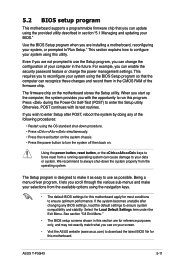
... and stability. Being a menu-driven program, it lets you are installing a motherboard, reconfiguring your BIOS." Even if you scroll through the various sub-menus and make it as possible. 5.2 BIOS setup program This motherboard supports a programmable firmware chip that the computer can recognize these changes and record them in section "5.1 Managing and updating your system, or prompted to"Run Setup." Using the power button, reset button, or the ++ keys to enter the Setup utility.
... and stability. Being a menu-driven program, it lets you are installing a motherboard, reconfiguring your BIOS." Even if you scroll through the various sub-menus and make it as possible. 5.2 BIOS setup program This motherboard supports a programmable firmware chip that the computer can recognize these changes and record them in section "5.1 Managing and updating your system, or prompted to"Run Setup." Using the power button, reset button, or the ++ keys to enter the Setup utility.
User Manual
Page 77
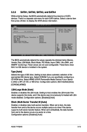
... entering Setup, the BIOS automatically detects the presence of IDE drive. These items show N/A if no IDE device is installed in the system. Type [Auto] Selects the type of SATA devices. Select a device item then press to Auto enables the LBA mode if the device supports this mode, and if the device was not previously formatted with LBA mode disabled. Configuration options: [Disabled] [Auto] ASUS T-P5G43 5-15 Configuration options: [Disabled] [Auto] Block (Multi-Sector Transfer) M [Auto] Enables or disables...
... entering Setup, the BIOS automatically detects the presence of IDE drive. These items show N/A if no IDE device is installed in the system. Type [Auto] Selects the type of SATA devices. Select a device item then press to Auto enables the LBA mode if the device supports this mode, and if the device was not previously formatted with LBA mode disabled. Configuration options: [Disabled] [Auto] ASUS T-P5G43 5-15 Configuration options: [Disabled] [Auto] Block (Multi-Sector Transfer) M [Auto] Enables or disables...
User Manual
Page 80
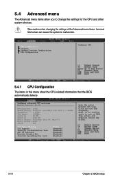
... changing the settings of the Advanced menu items. Incorrect field values can cause the system to change the settings for the CPU and other system devices. CPU Configuration Chipset Onboard Devices Configuration USB Configuration Configure CPU. 5.4.1 CPU Configuration The items in CMOS then actual and setpoint values may differ. 5-18 Chapter 5: BIOS setup Configure advanced CPU settings Module Version: 3D.0E Manufacturer: Intel Brand String: Inter(R) Core(TM)2 CPU 6300 @ 1.86GHz Frequency : 1.86GHz FSB Speed...
... changing the settings of the Advanced menu items. Incorrect field values can cause the system to change the settings for the CPU and other system devices. CPU Configuration Chipset Onboard Devices Configuration USB Configuration Configure CPU. 5.4.1 CPU Configuration The items in CMOS then actual and setpoint values may differ. 5-18 Chapter 5: BIOS setup Configure advanced CPU settings Module Version: 3D.0E Manufacturer: Intel Brand String: Inter(R) Core(TM)2 CPU 6300 @ 1.86GHz Frequency : 1.86GHz FSB Speed...
User Manual
Page 81
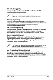
... the ratio manually, key in the number directly. Configuration options: [Disabled] [Enabled] CPU TM Function [Enabled] Enables or disables Intel® CPU Thermal Monitor (TM) function, a CPU overheating protection function. When enabled, the CPU core frequency and voltage are reduced when the CPU overheats. Configuration options: [Enabled] [Disabled] ASUS T-P5G43 5-19 When set to [Enabled], you need to use the EIST feature. Configuration options: [Auto] If you can adjust the system power settings in system halt state. C1E Support [Enabled] Allows you installed an...
... the ratio manually, key in the number directly. Configuration options: [Disabled] [Enabled] CPU TM Function [Enabled] Enables or disables Intel® CPU Thermal Monitor (TM) function, a CPU overheating protection function. When enabled, the CPU core frequency and voltage are reduced when the CPU overheats. Configuration options: [Enabled] [Disabled] ASUS T-P5G43 5-19 When set to [Enabled], you need to use the EIST feature. Configuration options: [Auto] If you can adjust the system power settings in system halt state. C1E Support [Enabled] Allows you installed an...
User Manual
Page 92
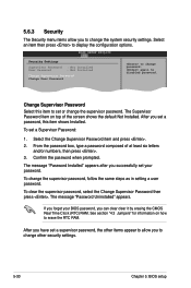
... 5: BIOS setup To change password. again to display the configuration options. The message "Password Installed" appears after you set a password, this item to set your BIOS password, you to erase the RTC RAM. Change Option F1 General Help F10 Save and Exit Select this item shows Installed. The message "Password Uninstalled" appears. After you successfully set or change the system security settings. From the password box, type a password composed of the screen shows the default Not Installed. Select Screen...
... 5: BIOS setup To change password. again to display the configuration options. The message "Password Installed" appears after you set a password, this item to set your BIOS password, you to erase the RTC RAM. Change Option F1 General Help F10 Save and Exit Select this item shows Installed. The message "Password Uninstalled" appears. After you successfully set or change the system security settings. From the password box, type a password composed of the screen shows the default Not Installed. Select Screen...
User Manual
Page 93
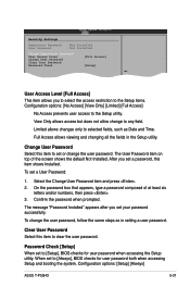
.../or numbers, then press . 3. After you set a User Password: 1. On the password box that appears, type a password composed of the screen shows the default Not Installed. The message "Password Installed" appears after you to select the access restriction to the Setup items. Configuration options: [No Access] [View Only] [Limited] [Full Access] No Access prevents user access to the Setup utility. Full Access allows viewing and changing all the fields in setting a user password. Confirm the password when prompted. Clear User Password Select...
.../or numbers, then press . 3. After you set a User Password: 1. On the password box that appears, type a password composed of the screen shows the default Not Installed. The message "Password Installed" appears after you to select the access restriction to the Setup items. Configuration options: [No Access] [View Only] [Limited] [Full Access] No Access prevents user access to the Setup utility. Full Access allows viewing and changing all the fields in setting a user password. Confirm the password when prompted. Clear User Password Select...


