T2-PE1 English User Manual E2151
Page 4
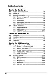
Table of contents Chapter 3: Starting up 3.1 Installing an operating system 3-2 3.2 Powering up 3-2 3.3 Support CD information 3-2 3.3.1 Running the support CD 3-3 3.3.2 Drivers menu 3-3 3.3.3 Utilities menu 3-4 3.3.4 ASUS contact information 3-5 3.3.5 Other information 3-6 3.4 Software information 3-7 3.4.1 ASUS Instant Music 3-7 3.4.2 ASUS Update 3-9 3.4.3 ASUS PC Probe II 3-11 Chapter 4: Motherboard Info 4.1 Introduction 4-2 4.2 Motherboard layout 4-2 4.3 Jumper 4-3 4.4 Connectors 4-4 Chapter 5: BIOS Information 5.1 Managing and updating your BIOS 5-2 5.1.1 Creating...
Table of contents Chapter 3: Starting up 3.1 Installing an operating system 3-2 3.2 Powering up 3-2 3.3 Support CD information 3-2 3.3.1 Running the support CD 3-3 3.3.2 Drivers menu 3-3 3.3.3 Utilities menu 3-4 3.3.4 ASUS contact information 3-5 3.3.5 Other information 3-6 3.4 Software information 3-7 3.4.1 ASUS Instant Music 3-7 3.4.2 ASUS Update 3-9 3.4.3 ASUS PC Probe II 3-11 Chapter 4: Motherboard Info 4.1 Introduction 4-2 4.2 Motherboard layout 4-2 4.3 Jumper 4-3 4.4 Connectors 4-4 Chapter 5: BIOS Information 5.1 Managing and updating your BIOS 5-2 5.1.1 Creating...
T2-PE1 English User Manual E2151
Page 8
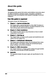
... is intended for this guide Audience This guide provides general information and installation instructions about the motherboard that comes with hardware knowledge of the ASUS Terminator 2. Chapter 1: System introduction This chapter gives a general description of personal computers. Chapter 5: BIOS information This chapter tells how to.... Chapter 3: Starting up This chapter helps you power up the system and install drivers and utilities from the support CD. 4 . This chapter includes the motherboard layout, jumper settings, and connector locations. 5. viii About this system.
... is intended for this guide Audience This guide provides general information and installation instructions about the motherboard that comes with hardware knowledge of the ASUS Terminator 2. Chapter 1: System introduction This chapter gives a general description of personal computers. Chapter 5: BIOS information This chapter tells how to.... Chapter 3: Starting up This chapter helps you power up the system and install drivers and utilities from the support CD. 4 . This chapter includes the motherboard layout, jumper settings, and connector locations. 5. viii About this system.
T2-PE1 English User Manual E2151
Page 10
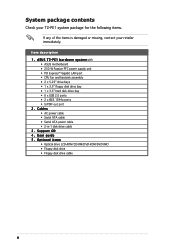
...ASUS motherboard • 250 W Passive PFC power supply unit • PCI Express™ Gigabit LAN port • CPU fan and heatsink assembly • 2 x 5.25" drive bays • 1 x 3.5" floppy disk drive bay • 1 x 3.5" hard disk drive bay • 6 x USB 2.0 ports • 2 x IEEE 1394a ports • S/PDIF out port 2 . Support CD... 4 . Optional items • Optical drive (CD-ROM/CD-RW/DVD-ROM/DVD-RW) • Floppy disk drive • Floppy disk drive cable x Item description 1 . A S U S T 2 - User guide 5 . System package contents Check your T2-PE1 system ...
...ASUS motherboard • 250 W Passive PFC power supply unit • PCI Express™ Gigabit LAN port • CPU fan and heatsink assembly • 2 x 5.25" drive bays • 1 x 3.5" floppy disk drive bay • 1 x 3.5" hard disk drive bay • 6 x USB 2.0 ports • 2 x IEEE 1394a ports • S/PDIF out port 2 . Support CD... 4 . Optional items • Optical drive (CD-ROM/CD-RW/DVD-ROM/DVD-RW) • Floppy disk drive • Floppy disk drive cable x Item description 1 . A S U S T 2 - User guide 5 . System package contents Check your T2-PE1 system ...
T2-PE1 English User Manual E2151
Page 35
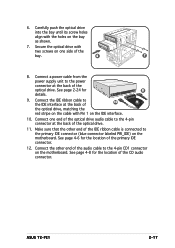
... cable with Pin 1 on the IDE interface. 10. See page 2-24 for the location of the CD audio connector. Connect the other end of the bay. 6 7 8. Secure the optical drive with the holes on the motherboard. ASUS T2-PE1 2-17 See page 4-8 for the location of the primary IDE connector. 12. Connect one side...
... cable with Pin 1 on the IDE interface. 10. See page 2-24 for the location of the CD audio connector. Connect the other end of the bay. 6 7 8. Secure the optical drive with the holes on the motherboard. ASUS T2-PE1 2-17 See page 4-8 for the location of the primary IDE connector. 12. Connect one side...
T2-PE1 English User Manual E2151
Page 45
Chapter 3 This chapter helps you power up ASUS T2-PE1 Starting up the system and install drivers and utilities from the support CD.
Chapter 3 This chapter helps you power up ASUS T2-PE1 Starting up the system and install drivers and utilities from the support CD.
T2-PE1 English User Manual E2151
Page 46
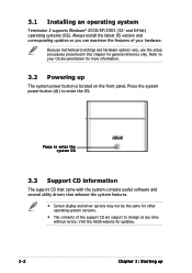
Press the system power button ( ) to your hardware. Press to change at any time without notice. Visit the ASUS website for more information. 3.2 Powering up Because motherboard settings and hardware options vary, use the setup procedures presented in this chapter for...OS). Always install the latest OS version and corresponding updates so you can maximize the features of the support CD are subject to enter the system OS 3.3 Support CD information The support CD that came with the system contains useful software and several utility drivers that enhance the system features. •...
Press the system power button ( ) to your hardware. Press to change at any time without notice. Visit the ASUS website for more information. 3.2 Powering up Because motherboard settings and hardware options vary, use the setup procedures presented in this chapter for...OS). Always install the latest OS version and corresponding updates so you can maximize the features of the support CD are subject to enter the system OS 3.3 Support CD information The support CD that came with the system contains useful software and several utility drivers that enhance the system features. •...
T2-PE1 English User Manual E2151
Page 47
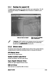
...BIN folder. Double-click the A S S E T U P . Click an item to install Click an icon to run the CD. 3.3.2 Drivers menu The drivers menu shows the available device drivers if the system detects installed devices. Install the necessary drivers to install ...CD automatically displays the D r i v e r s menu if Autorun is NOT enabled in your computer. Realtek ALC655 Audio Driver Installs the Realtek® ALC655 audio driver. USB 2.0 Driver Click this item to activate the devices. E X E to display other information If A u t o r u n is enabled in your optical drive. ASUS T2-PE1...
...BIN folder. Double-click the A S S E T U P . Click an item to install Click an icon to run the CD. 3.3.2 Drivers menu The drivers menu shows the available device drivers if the system detects installed devices. Install the necessary drivers to install ...CD automatically displays the D r i v e r s menu if Autorun is NOT enabled in your computer. Realtek ALC655 Audio Driver Installs the Realtek® ALC655 audio driver. USB 2.0 Driver Click this item to activate the devices. E X E to display other information If A u t o r u n is enabled in your optical drive. ASUS T2-PE1...

T2-PE1 English User Manual E2151
Page 50
3.3.5 Other information The icons on the top right side of the screen provide additional information on the motherboard and the contents of the support CD. 3-6 Chapter 3: Starting up
3.3.5 Other information The icons on the top right side of the screen provide additional information on the motherboard and the contents of the support CD. 3-6 Chapter 3: Starting up
T2-PE1 English User Manual E2151
Page 51
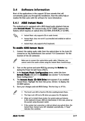
... Setup. The hot key is . • The Scroll Lock LED is equipped with a BIOS-based audio playback feature called I n s t a n t M u s i c. 3.4 Software information Most of the CD connector. ASUS T2-PE1 3-7 View the online help or readme file that will conveniently guide you through the installation. See section "5.4.6 Instant Music Configuration." 4. In this condition. See section...
... Setup. The hot key is . • The Scroll Lock LED is equipped with a BIOS-based audio playback feature called I n s t a n t M u s i c. 3.4 Software information Most of the CD connector. ASUS T2-PE1 3-7 View the online help or readme file that will conveniently guide you through the installation. See section "5.4.6 Instant Music Configuration." 4. In this condition. See section...
T2-PE1 English User Manual E2151
Page 52
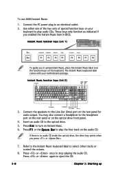
... the Instant Music item in using Instant Music, place the Instant Music label over the function keys on the audio CD. DOWN VOL. UP 3. You may also connect a headphone to an electrical outlet. 2. Press F 1 or ...VOL. Press E s c to stop playing the audio CD. Press or once to turn on the rear panel for audio output. To use ASUS Instant Music: 1. UP F5 F6 F7 F8 To guide... you press or . 7. Instant Music function keys (Set 2) CD ON/OFF CAPS SCROLL LOCK LOCK LED LED PLAY/PAUSE STOP/EJECT PREVIOUS NEXT VOL. Insert an audio CD...
... the Instant Music item in using Instant Music, place the Instant Music label over the function keys on the audio CD. DOWN VOL. UP 3. You may also connect a headphone to an electrical outlet. 2. Press F 1 or ...VOL. Press E s c to stop playing the audio CD. Press or once to turn on the rear panel for audio output. To use ASUS Instant Music: 1. UP F5 F6 F7 F8 To guide... you press or . 7. Instant Music function keys (Set 2) CD ON/OFF CAPS SCROLL LOCK LOCK LED LED PLAY/PAUSE STOP/EJECT PREVIOUS NEXT VOL. Insert an audio CD...
T2-PE1 English User Manual E2151
Page 55
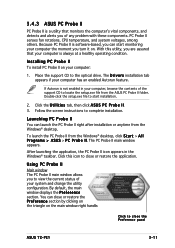
...screen instructions to the optical drive. If Autorun is software-based, you turn it on your computer the moment you can close the Preference panel ASUS T2-PE1 3-11 Click this utility, you are assured that monitors the computer's vital components, and detects and alerts you to locate the setup.exe file... from the ASUS PC Probe II folder. Using PC Probe II Main window The PC Probe II main window allows you of the support CD to view the current status of your computer has an enabled Autorun feature. The...
...screen instructions to the optical drive. If Autorun is software-based, you turn it on your computer the moment you can close the Preference panel ASUS T2-PE1 3-11 Click this utility, you are assured that monitors the computer's vital components, and detects and alerts you to locate the setup.exe file... from the ASUS PC Probe II folder. Using PC Probe II Main window The PC Probe II main window allows you of the support CD to view the current status of your computer has an enabled Autorun feature. The...
T2-PE1 English User Manual E2151
Page 62
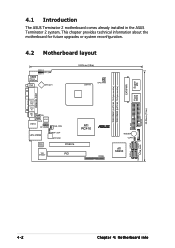
... 2 motherboard comes already installed in the ASUS Terminator 2 system. This chapter provides technical information about the motherboard for future upgrades or system reconfiguration. 4.2 Motherboard layout KBMS T:Mouse B:Keyboard VGA IOC_MB ATX12V1 24....-bit, 184-pin module) DDR DIMM2 (64/72-bit, 184-pin module) PARALLEL PORT PRI_IDE FLOPPY 20.06cm (7.9in) Line Out Line In Mic In CD USB12 ALC655 AUX FP_AUDIO CHA_FAN LAN_USB34 SPDIF_OUT ATX12V2 Marvell 88E8053 PCIEX16 ATI RC410 VIA VT6307 PCI ¤ PANEL BUZZER CLRTC BAT ATI SB450 SATA4 SATA2...
... 2 motherboard comes already installed in the ASUS Terminator 2 system. This chapter provides technical information about the motherboard for future upgrades or system reconfiguration. 4.2 Motherboard layout KBMS T:Mouse B:Keyboard VGA IOC_MB ATX12V1 24....-bit, 184-pin module) DDR DIMM2 (64/72-bit, 184-pin module) PARALLEL PORT PRI_IDE FLOPPY 20.06cm (7.9in) Line Out Line In Mic In CD USB12 ALC655 AUX FP_AUDIO CHA_FAN LAN_USB34 SPDIF_OUT ATX12V2 Marvell 88E8053 PCIEX16 ATI RC410 VIA VT6307 PCI ¤ PANEL BUZZER CLRTC BAT ATI SB450 SATA4 SATA2...

T2-PE1 English User Manual E2151
Page 68
... 1. Insert one end of the cable to this connector, then connect the other end to receive stereo audio input from sound sources such as a CD-ROM, TV tuner, or MPEG card. FLOPPY ¤ Floppy disk drive connector PIN 1 NOTE: Orient the red markings on the connector is for... cable to prevent incorrect cable connection when using an FDD cable with a covered Pin 5. 4-8 Chapter 4: Motherboard info Internal audio connectors (4-pin AUX, CD) These connectors allow you to the signal connector at the back of the floppy disk drive. Right Audio Channel Ground Left Audio Channel Right Audio...
... 1. Insert one end of the cable to this connector, then connect the other end to receive stereo audio input from sound sources such as a CD-ROM, TV tuner, or MPEG card. FLOPPY ¤ Floppy disk drive connector PIN 1 NOTE: Orient the red markings on the connector is for... cable to prevent incorrect cable connection when using an FDD cable with a covered Pin 5. 4-8 Chapter 4: Motherboard info Internal audio connectors (4-pin AUX, CD) These connectors allow you to the signal connector at the back of the floppy disk drive. Right Audio Channel Ground Left Audio Channel Right Audio...

T2-PE1 English User Manual E2151
Page 72
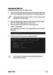
... S t a r t, then select R u n. 5-2 Chapter 5: BIOS setup A S U S E Z F l a s h (Updates the BIOS using the ASUS Update or AFUDOS utilities. 5.1.1 Creating a bootable floppy disk 1. A S U S U p d a t e (Updates the BIOS in the future. Copy the original ... select M y C o m p u t e r. Do either one of the original motherboard BIOS file to a bootable floppy disk in DOS mode using a bootable floppy disk or the motherboard support CD when the BIOS file fails or gets corrupted.) 4. Insert a 1.44MB floppy disk into the drive. b. A S U S C r a s h F r e e B I O S 2 (Updates the BIOS ...
... S t a r t, then select R u n. 5-2 Chapter 5: BIOS setup A S U S E Z F l a s h (Updates the BIOS using the ASUS Update or AFUDOS utilities. 5.1.1 Creating a bootable floppy disk 1. A S U S U p d a t e (Updates the BIOS in the future. Copy the original ... select M y C o m p u t e r. Do either one of the original motherboard BIOS file to a bootable floppy disk in DOS mode using a bootable floppy disk or the motherboard support CD when the BIOS file fails or gets corrupted.) 4. Insert a 1.44MB floppy disk into the drive. b. A S U S C r a s h F r e e B I O S 2 (Updates the BIOS ...

T2-PE1 English User Manual E2151
Page 74
Copy the AFUDOS utility (afudos.exe) from the motherboard support CD to the bootable floppy disk you to update the BIOS file in DOS mode, then at the prompt type: afudos /o[filename] where the [filename] is ...
Copy the AFUDOS utility (afudos.exe) from the motherboard support CD to the bootable floppy disk you to update the BIOS file in DOS mode, then at the prompt type: afudos /o[filename] where the [filename] is ...
T2-PE1 English User Manual E2151
Page 75
... you created earlier. 3. Copy the AFUDOS utility (afudos.exe) from the motherboard support CD to prevent system boot failure! ASUS T2-PE1 5-5 Visit the ASUS website (www.asus.com) and download the latest BIOS file for the motherboard. A:\>afudos /iP54RT.ROM 4. Version 1.19(ASUS V2.07(03.11.24BB)) Copyright (C) 2003 American Megatrends, Inc. Do not turn...
... you created earlier. 3. Copy the AFUDOS utility (afudos.exe) from the motherboard support CD to prevent system boot failure! ASUS T2-PE1 5-5 Visit the ASUS website (www.asus.com) and download the latest BIOS file for the motherboard. A:\>afudos /iP54RT.ROM 4. Version 1.19(ASUS V2.07(03.11.24BB)) Copyright (C) 2003 American Megatrends, Inc. Do not turn...

T2-PE1 English User Manual E2151
Page 76
...BIOS 2 is completed. Turn on the system. 2. A:\>afudos /iP54RT.ROM AMI Firmware Update Utility - All rights reserved. Erasing flash ..... Version 1.19(ASUS V2.07(03.11.24BB)) Copyright (C) 2003 American Megatrends, Inc. R O M. Insert the floppy disk with the original or updated BIOS file to...1. done Writing flash ..... You can update a corrupted BIOS file using the motherboard support CD or the floppy disk that contains the updated BIOS file. • Prepare the motherboard support CD or the floppy disk containing the updated motherboard BIOS before using this utility. •...
...BIOS 2 is completed. Turn on the system. 2. A:\>afudos /iP54RT.ROM AMI Firmware Update Utility - All rights reserved. Erasing flash ..... Version 1.19(ASUS V2.07(03.11.24BB)) Copyright (C) 2003 American Megatrends, Inc. R O M. Insert the floppy disk with the original or updated BIOS file to...1. done Writing flash ..... You can update a corrupted BIOS file using the motherboard support CD or the floppy disk that contains the updated BIOS file. • Prepare the motherboard support CD or the floppy disk containing the updated motherboard BIOS before using this utility. •...

T2-PE1 English User Manual E2151
Page 77
...Starting BIOS recovery... Checking for floppy... Reading file "P54RT.ROM". ASUS T2-PE1 5-7 Starting BIOS recovery... Bad BIOS checksum. Starting BIOS recovery... Doing so can cause system boot failure! 4. Remove any floppy disk from the support CD: 1. When no floppy disk is found, the utility automatically checks ...the optical drive for floppy... Checking for the original or updated BIOS file. CD-ROM found , the utility reads the BIOS file and starts flashing the corrupted BIOS file. When found ! Reading file "...
...Starting BIOS recovery... Checking for floppy... Reading file "P54RT.ROM". ASUS T2-PE1 5-7 Starting BIOS recovery... Bad BIOS checksum. Starting BIOS recovery... Doing so can cause system boot failure! 4. Remove any floppy disk from the support CD: 1. When no floppy disk is found, the utility automatically checks ...the optical drive for floppy... Checking for the original or updated BIOS file. CD-ROM found , the utility reads the BIOS file and starts flashing the corrupted BIOS file. When found ! Reading file "...
T2-PE1 English User Manual E2151
Page 78
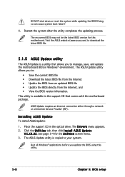
... a l l A S U S U p d a t e V X . X X. Restart the system after the utility completes the updating process. This utility is copied to your system. Place the support CD in the support CD that allows you update the BIOS using this motherboard. The recovered BIOS may not be the latest BIOS version for the U t i l i t i e s screen menu. 3. The... ASUS Update utility is available in the optical drive. ...
... a l l A S U S U p d a t e V X . X X. Restart the system after the utility completes the updating process. This utility is copied to your system. Place the support CD in the support CD that allows you update the BIOS using this motherboard. The recovered BIOS may not be the latest BIOS version for the U t i l i t i e s screen menu. 3. The... ASUS Update utility is available in the optical drive. ...

T2-PE1 English User Manual E2151
Page 83
... [[111.:414M0,:139.]5 in] System Date LPergiamcaryy DIiDsEkeMtatseterA Primary IDE Slave [Fri 07/15/2005] :[[1S.T4342M04,103A.]5 in.] : [ASUS CD-S520/A] OnboarPdriPmCaIryS-IADTEA Mcoansttreorller [[NDoitsaDbleetde]cted] Primary IDE Slave [Not Detected] Serial ATA Port1 [Not Detected] Serial ATA Port2 [Not Detected...description of options. Plug And Play O/S PCI Latency Timer Allocate IRQ to display a list of the selected item. Scroll bar ASUS T2-PE1 5-13 5.2.4 Menu items The highlighted item on the screen. A configurable field is enclosed in below sections may cause system ...
... [[111.:414M0,:139.]5 in] System Date LPergiamcaryy DIiDsEkeMtatseterA Primary IDE Slave [Fri 07/15/2005] :[[1S.T4342M04,103A.]5 in.] : [ASUS CD-S520/A] OnboarPdriPmCaIryS-IADTEA Mcoansttreorller [[NDoitsaDbleetde]cted] Primary IDE Slave [Not Detected] Serial ATA Port1 [Not Detected] Serial ATA Port2 [Not Detected...description of options. Plug And Play O/S PCI Latency Timer Allocate IRQ to display a list of the selected item. Scroll bar ASUS T2-PE1 5-13 5.2.4 Menu items The highlighted item on the screen. A configurable field is enclosed in below sections may cause system ...


