
User Manual
Page 1
R SP97/SP97-V Pentium® Motherboard USER'S MANUAL
R SP97/SP97-V Pentium® Motherboard USER'S MANUAL
User Manual
Page 2
... kept by the purchaser for backup purposes, without intent to the owners' benefit, without the express written permission of ASUSTeK COMPUTER INC. ("ASUS"). Product Name: ASUS SP97 / SP97-V Manual Revision: 1.02 Release Date: July 1997 2 ASUS SP97 / SP97-V User's Manual The product name and revision number are both printed on the following page. Copyright © 1997 ASUSTeK COMPUTER INC...
... kept by the purchaser for backup purposes, without intent to the owners' benefit, without the express written permission of ASUSTeK COMPUTER INC. ("ASUS"). Product Name: ASUS SP97 / SP97-V Manual Revision: 1.02 Release Date: July 1997 2 ASUS SP97 / SP97-V User's Manual The product name and revision number are both printed on the following page. Copyright © 1997 ASUSTeK COMPUTER INC...

User Manual
Page 3
...Technical Support Fax: +886-2-895-9254 BBS: +886-2-896-4667 Email: tsd@asus.com.tw WWW: www.asus.com.tw Gopher: gopher.asus.com.tw FTP: ftp.asus.com.tw/pub/ASUS ASUS COMPUTER INTERNATIONAL Marketing Info Address: 721 Charcot Avenue, San Jose, CA 95131, ...asus.com.tw WWW: www.asus.com ASUS COMPUTER GmbH Marketing Info Address: Harkort Str. 25, 40880 Ratingen, BRD, Germany Telephone: 49-2102-445011 Fax: 49-2102-442066 Email: info-ger@asus.com.tw Technical Support BBS: 49-2102-448690 Email: tsd-ger@asus.com.tw Hotline: 49-2102-499712 ASUS SP97 / SP97-V User's Manual...
...Technical Support Fax: +886-2-895-9254 BBS: +886-2-896-4667 Email: tsd@asus.com.tw WWW: www.asus.com.tw Gopher: gopher.asus.com.tw FTP: ftp.asus.com.tw/pub/ASUS ASUS COMPUTER INTERNATIONAL Marketing Info Address: 721 Charcot Avenue, San Jose, CA 95131, ...asus.com.tw WWW: www.asus.com ASUS COMPUTER GmbH Marketing Info Address: Harkort Str. 25, 40880 Ratingen, BRD, Germany Telephone: 49-2102-445011 Fax: 49-2102-442066 Email: info-ger@asus.com.tw Technical Support BBS: 49-2102-448690 Email: tsd-ger@asus.com.tw Hotline: 49-2102-499712 ASUS SP97 / SP97-V User's Manual...

User Manual
Page 4
... Feature Menu 37 Managing and Updating Your Motherboard's BIOS 38 6. INSTALLATION 12 ASUS SP97 Motherboard Layout 12 Installation Steps 14 1. FEATURES 8 Features of the ASUS SP97 Motherboard 8 Introduction to ASUS SP97 Series of PNP and PCI Setup 50 Load BIOS Defaults 52 4 ASUS SP97 / SP97-V User's Manual BIOS Setup 39 Load Defaults 40 Standard CMOS Setup 40 Details of Standard...
... Feature Menu 37 Managing and Updating Your Motherboard's BIOS 38 6. INSTALLATION 12 ASUS SP97 Motherboard Layout 12 Installation Steps 14 1. FEATURES 8 Features of the ASUS SP97 Motherboard 8 Introduction to ASUS SP97 Series of PNP and PCI Setup 50 Load BIOS Defaults 52 4 ASUS SP97 / SP97-V User's Manual BIOS Setup 39 Load Defaults 40 Standard CMOS Setup 40 Details of Standard...

User Manual
Page 5
...Software Drivers 74 1. Windows 3.1 75 2. SUPPORT SOFTWARE 56 Desktop Management Interface (DMI 56 Introducing the ASUS DMI Configuration Utility 56 System Requirements 56 Using the ASUS DMI Configuration Utility 57 Notes 57 VI. Windows 95 81 5. OS/2 V3.0 (Warp 93 8. ...ASUS I-A16C Audio Card 63 ASUS I-A16C Audio Features 63 Unpacking and Handling Precautions 63 Layout and Connectors 64 Connectors 64 CD-Audio Connector Pin Definitions 64 VIDEO SOFTWARE MANUAL (with onboard 5598 VGA only) .. 65 VIII. OS/2 V2.1 92 7. Double Bytes OS/2 Warp 94 ASUS SP97 / SP97-V User's Manual...
...Software Drivers 74 1. Windows 3.1 75 2. SUPPORT SOFTWARE 56 Desktop Management Interface (DMI 56 Introducing the ASUS DMI Configuration Utility 56 System Requirements 56 Using the ASUS DMI Configuration Utility 57 Notes 57 VI. Windows 95 81 5. OS/2 V3.0 (Warp 93 8. ...ASUS I-A16C Audio Card 63 ASUS I-A16C Audio Features 63 Unpacking and Handling Precautions 63 Layout and Connectors 64 Connectors 64 CD-Audio Connector Pin Definitions 64 VIDEO SOFTWARE MANUAL (with onboard 5598 VGA only) .. 65 VIII. OS/2 V2.1 92 7. Double Bytes OS/2 Warp 94 ASUS SP97 / SP97-V User's Manual...

User Manual
Page 6
.... However, there is encouraged to try to radio communications. Changes or modifications to this unit not expressly approved by one or more of Communications. 6 ASUS SP97 / SP97-V User's Manual Canadian Department of Communications Statement This digital apparatus does not exceed the Class B limits for radio noise emissions from that to which can radiate radio...
.... However, there is encouraged to try to radio communications. Changes or modifications to this unit not expressly approved by one or more of Communications. 6 ASUS SP97 / SP97-V User's Manual Canadian Department of Communications Statement This digital apparatus does not exceed the Class B limits for radio noise emissions from that to which can radiate radio...
User Manual
Page 7
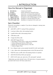
I . INTRODUCTION How this Manual is complete. ASUS SP97 / SP97-V User's Manual 7 Support Software VI. ASUS SP97 or SP97-V (onboard VGA) motherboard 2 serial port ribbon cables with mounting brackets 1 parallel ribbon cable with mounting bracket 1 IDE ribbon cable 1 floppy disk ribbon cable ASUS SP97 Support Drivers • Flash Memory Writer utility to update the FLASH BIOS • Desktop Management Interface (DMI) utility...
I . INTRODUCTION How this Manual is complete. ASUS SP97 / SP97-V User's Manual 7 Support Software VI. ASUS SP97 or SP97-V (onboard VGA) motherboard 2 serial port ribbon cables with mounting brackets 1 parallel ribbon cable with mounting bracket 1 IDE ribbon cable 1 floppy disk ribbon cable ASUS SP97 Support Drivers • Flash Memory Writer utility to update the FLASH BIOS • Desktop Management Interface (DMI) utility...

User Manual
Page 8
... BIOS that supports autodetection of hard disk drives, PS/2 mouse, and Plug and Play devices to 33MB/sec IDE transfers and Enhanced IDE devices. FEATURES (ASUS SP97) II. Supports four IDE devices more than 8.4GB in a small package, namely: • SiS Chipset: Features either 5.25- (360KB or 1.2KB) or 3.5-inch disk... an onboard Ultra DMA/33 Bus Master IDE controller with EPP and ECP capabilities. • Desktop Management Interface (DMI): Supports DMI through onboard firmware. 8 ASUS SP97 / SP97-V User's Manual II. Also supports PIO Modes 3 and 4 and Bus Master IDE DMA Mode 2.
... BIOS that supports autodetection of hard disk drives, PS/2 mouse, and Plug and Play devices to 33MB/sec IDE transfers and Enhanced IDE devices. FEATURES (ASUS SP97) II. Supports four IDE devices more than 8.4GB in a small package, namely: • SiS Chipset: Features either 5.25- (360KB or 1.2KB) or 3.5-inch disk... an onboard Ultra DMA/33 Bus Master IDE controller with EPP and ECP capabilities. • Desktop Management Interface (DMI): Supports DMI through onboard firmware. 8 ASUS SP97 / SP97-V User's Manual II. Also supports PIO Modes 3 and 4 and Bus Master IDE DMA Mode 2.

User Manual
Page 9
... UltraDMA/33 IDE, which can be used. • PC '97 Compliant: Both the BIOS and hardware levels of ASUS SP97 series of motherboards with SiS 5582 or SiS 5598 (with existing ATA-2 IDE specifications so there is also implemented on the...ASUS SiS 5582 or SiS 5598 (with VGA) series of motherboards. FEATURES Introduction to ASUS SP97 Series of Motherboards Performance • Double the IDE Transfer Speed: ASUS SP97 series of motherboards meet PC '97 compliancy. With these features implemented in the OS, PCs can handle data transfers up to 33MB/s. ASUS SP97 / SP97-V User's Manual...
... UltraDMA/33 IDE, which can be used. • PC '97 Compliant: Both the BIOS and hardware levels of ASUS SP97 series of motherboards with SiS 5582 or SiS 5598 (with existing ATA-2 IDE specifications so there is also implemented on the...ASUS SiS 5582 or SiS 5598 (with VGA) series of motherboards. FEATURES Introduction to ASUS SP97 Series of Motherboards Performance • Double the IDE Transfer Speed: ASUS SP97 series of motherboards meet PC '97 compliancy. With these features implemented in the OS, PCs can handle data transfers up to 33MB/s. ASUS SP97 / SP97-V User's Manual...

User Manual
Page 10
(This page was intentionally left blank) 10 ASUS SP97 / SP97-V User's Manual
(This page was intentionally left blank) 10 ASUS SP97 / SP97-V User's Manual

User Manual
Page 11
ATX Power Conn. II. Floppy Connector IDE Connectors USB, PS/2 Mouse, Infrared Super Multi I/O Parallel Serial Keyboard 4 SIMM Sockets SiS5582 or 5598 (VGA) Chipset Programmable Flash ROM CPU ZIF Socket 7 Switching Voltage Regulators 512KB/256KB Pipelined Burst L2 Cache ASUS SP97 / SP97-V User's Manual 11 FEATURES (ASUS SP97) II. FEATURES The ASUS SP97 Motherboard 3 PCI Slots 2 ISA Slots 1 ISA/PCI Shared Slot AT Power Conn.
ATX Power Conn. II. Floppy Connector IDE Connectors USB, PS/2 Mouse, Infrared Super Multi I/O Parallel Serial Keyboard 4 SIMM Sockets SiS5582 or 5598 (VGA) Chipset Programmable Flash ROM CPU ZIF Socket 7 Switching Voltage Regulators 512KB/256KB Pipelined Burst L2 Cache ASUS SP97 / SP97-V User's Manual 11 FEATURES (ASUS SP97) II. FEATURES The ASUS SP97 Motherboard 3 PCI Slots 2 ISA Slots 1 ISA/PCI Shared Slot AT Power Conn.

User Manual
Page 12
Panel Connectors 12 ASUS SP97 / SP97-V User's Manual INSTALLATION (Motherboard Layout) III. INSTALLATION ASUS SP97 Motherboard Layout PCI Slot 3 PCI Slot 4 ISA Slot 1 Feature Connector ISA Slot 2 ISA Slot 3 USB, PS/2 Mouse, IrDA PCI Slot 1 PCI Slot 2 Super Multi-I/O VGA ...
Panel Connectors 12 ASUS SP97 / SP97-V User's Manual INSTALLATION (Motherboard Layout) III. INSTALLATION ASUS SP97 Motherboard Layout PCI Slot 3 PCI Slot 4 ISA Slot 1 Feature Connector ISA Slot 2 ISA Slot 3 USB, PS/2 Mouse, IrDA PCI Slot 1 PCI Slot 2 Super Multi-I/O VGA ...

User Manual
Page 13
...) 18) IDELED p. 32 IDE Activity LED (2 pins) 19) VGACON (optional) p. 32 VGA Connector (16-pin block) 20) FEATURE p. 33 Video Feature Connector (28-pin block) ASUS SP97 / SP97-V User's Manual 13
...) 18) IDELED p. 32 IDE Activity LED (2 pins) 19) VGACON (optional) p. 32 VGA Connector (16-pin block) 20) FEATURE p. 33 Video Feature Connector (28-pin block) ASUS SP97 / SP97-V User's Manual 13

User Manual
Page 14
... no connection, connect pins 1 & 2, and connect pins 2 & 3, respectively. The jumpers will be sharing pins from the system. 14 ASUS SP97 / SP97-V User's Manual Settings with two jumper numbers require that came with three pins. WARNING! Unplug your computer. 1. Place components on a grounded antistatic pad or ...Integrated Circuit (IC) chips. III. A "1" is always on top or on the motherboard. Use the diagrams in this manual instead of your computer, you must follow some precautions whenever you must complete the following the pin layout on the Motherboard 2. ...
... no connection, connect pins 1 & 2, and connect pins 2 & 3, respectively. The jumpers will be sharing pins from the system. 14 ASUS SP97 / SP97-V User's Manual Settings with two jumper numbers require that came with three pins. WARNING! Unplug your computer. 1. Place components on a grounded antistatic pad or ...Integrated Circuit (IC) chips. III. A "1" is always on top or on the motherboard. Use the diagrams in this manual instead of your computer, you must follow some precautions whenever you must complete the following the pin layout on the Motherboard 2. ...

User Manual
Page 15
... BIOS to "Load Setup Defaults" and reenter any user information after removing and reapplying this jumper and attaching a current meter to pins 1 & 2. III. INSTALLATION (Jumpers) ASUS SP97 / SP97-V User's Manual 15 The CMOS RAM containing BIOS setup information may be cleared by the onboard button cell battery.
... BIOS to "Load Setup Defaults" and reenter any user information after removing and reapplying this jumper and attaching a current meter to pins 1 & 2. III. INSTALLATION (Jumpers) ASUS SP97 / SP97-V User's Manual 15 The CMOS RAM containing BIOS setup information may be cleared by the onboard button cell battery.

User Manual
Page 16
.../MX (2.8Volts) P54C/CS/K5 (3.4V) (STD) K6-166/200 (2.9Volts) CPU Vcore Voltage ID Selection 1 2 3 K6-233 (3.2Volts) 1 2 3 P54C/CS/6x86 (3.5V) (VRE) 16 ASUS SP97 / SP97-V User's Manual The voltage regulators will automatically detect and switch between Single Power Plane & Dual Power Planes.
.../MX (2.8Volts) P54C/CS/K5 (3.4V) (STD) K6-166/200 (2.9Volts) CPU Vcore Voltage ID Selection 1 2 3 K6-233 (3.2Volts) 1 2 3 P54C/CS/6x86 (3.5V) (VRE) 16 ASUS SP97 / SP97-V User's Manual The voltage regulators will automatically detect and switch between Single Power Plane & Dual Power Planes.

User Manual
Page 17
... 1.5x(3/2) 2.0x(2/1) 2.5x(5/2) 3.0x(3/1) ---- ---- These must be set the frequency ratio between the internal frequency of the CPU's external frequency (or BUS Clock). INSTALLATION (Jumpers) ASUS SP97 / SP97-V User's Manual 17 P55C/K6/MX 3.5x(7/2) 2.0x(2/1) 2.5x(5/2) 3.0x(3/1) 4.0x(4/1) 4.5x(9/2) IBM/Cyrix 6x86 3.0x(3/1) 2.0x(2/1) 1.0x(1/1) 4.0x(4/1) ---- ---- The BUS Clock multiplied by the BUS...
... 1.5x(3/2) 2.0x(2/1) 2.5x(5/2) 3.0x(3/1) ---- ---- These must be set the frequency ratio between the internal frequency of the CPU's external frequency (or BUS Clock). INSTALLATION (Jumpers) ASUS SP97 / SP97-V User's Manual 17 P55C/K6/MX 3.5x(7/2) 2.0x(2/1) 2.5x(5/2) 3.0x(3/1) 4.0x(4/1) 4.5x(9/2) IBM/Cyrix 6x86 3.0x(3/1) 2.0x(2/1) 1.0x(1/1) 4.0x(4/1) ---- ---- The BUS Clock multiplied by the BUS...

User Manual
Page 18
... 1.5x 66MHz [2-3] [1-2] [2-3] [1-2] 90MHz 1.5x 60MHz [1-2] [2-3] [2-3] [1-2] 75MHz 1.5x 50MHz [2-3] [2-3] [2-3] [1-2] (Freq. Bootup screen will show 6x86-P166+ with the Cyrix PR166+ installed on this motherboard. 18 ASUS SP97 / SP97-V User's Manual INSTALLATION Set the jumpers according to the internal speed of your processor as follows: CPU Model Intel Pentium Intel Pentium Intel Pentium Intel Pentium Intel...
... 1.5x 66MHz [2-3] [1-2] [2-3] [1-2] 90MHz 1.5x 60MHz [1-2] [2-3] [2-3] [1-2] 75MHz 1.5x 50MHz [2-3] [2-3] [2-3] [1-2] (Freq. Bootup screen will show 6x86-P166+ with the Cyrix PR166+ installed on this motherboard. 18 ASUS SP97 / SP97-V User's Manual INSTALLATION Set the jumpers according to the internal speed of your processor as follows: CPU Model Intel Pentium Intel Pentium Intel Pentium Intel Pentium Intel...

User Manual
Page 19
... VGA (Default) Disable VGA Onboard VGA 6. You need to disable the onboard VGA to turn the onboard VGA on VGA expansion card. INSTALLATION (Jumpers) ASUS SP97 / SP97-V User's Manual 19 VGA_SEL VGA_INT VGA_SEL1 VGA_SEL VGA_INT VGA_SEL1 R Interrupt Disabled (Default) Interrupt by the onboard chipset. The default disables the chipset's internal interrupt routing. VGA Selection...
... VGA (Default) Disable VGA Onboard VGA 6. You need to disable the onboard VGA to turn the onboard VGA on VGA expansion card. INSTALLATION (Jumpers) ASUS SP97 / SP97-V User's Manual 19 VGA_SEL VGA_INT VGA_SEL1 VGA_SEL VGA_INT VGA_SEL1 R Interrupt Disabled (Default) Interrupt by the onboard chipset. The default disables the chipset's internal interrupt routing. VGA Selection...

User Manual
Page 20
... not use memory modules with memory chips) of the memory subsystem and will be filled before Sockets 3&4. Sockets 3&4 may be unstable. INSTALLATION (System Memory) 20 ASUS SP97 / SP97-V User's Manual IMPORTANT: Memory speed is set "Auto Configuration" to 70ns. Memory Socket SIMM Sockets 1&2 (Rows 0 & 1) SIMM Sockets 3&4 (Rows 2 & 3) SIMM Memory Module 4MB, 8MB, 16MB, 32MB...
... not use memory modules with memory chips) of the memory subsystem and will be filled before Sockets 3&4. Sockets 3&4 may be unstable. INSTALLATION (System Memory) 20 ASUS SP97 / SP97-V User's Manual IMPORTANT: Memory speed is set "Auto Configuration" to 70ns. Memory Socket SIMM Sockets 1&2 (Rows 0 & 1) SIMM Sockets 3&4 (Rows 2 & 3) SIMM Memory Module 4MB, 8MB, 16MB, 32MB...


