
User Guide
Page 23
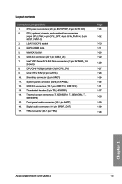
...audio connector (4-1 pin SPDIF_OUT) 17. Clear RTC RAM (3-pin CLRTC) 10. Layout contents Connectors/Jumpers/Slots 1. ATX power connectors (24-pin EATXPWR, 8-pin EATX12V) 2. Intel® Z97 Serial ATA 6.0 Gb/s connectors (7-pin SATA6G_1-6... [brown]) 8. Thermal sensor connectors (T_SENSOR1, T_SENSOR2, T_ SENSOR3) 15. Front panel audio connector (10-1 pin AAFP) 16. TPM connector (20-1 pin TPM) Page 1-34 1-32 1-10 1-11 1-25 1-30 1-29 1-27 1-26 1-36 1-35 1-31 1-37 1-33 1-33 1-30 1-36 Chapter 1 ASUS SABERTOOTH Z97 MARK...
...audio connector (4-1 pin SPDIF_OUT) 17. Clear RTC RAM (3-pin CLRTC) 10. Layout contents Connectors/Jumpers/Slots 1. ATX power connectors (24-pin EATXPWR, 8-pin EATX12V) 2. Intel® Z97 Serial ATA 6.0 Gb/s connectors (7-pin SATA6G_1-6... [brown]) 8. Thermal sensor connectors (T_SENSOR1, T_SENSOR2, T_ SENSOR3) 15. Front panel audio connector (10-1 pin AAFP) 16. TPM connector (20-1 pin TPM) Page 1-34 1-32 1-10 1-11 1-25 1-30 1-29 1-27 1-26 1-36 1-35 1-31 1-37 1-33 1-33 1-30 1-36 Chapter 1 ASUS SABERTOOTH Z97 MARK...
User Guide
Page 40
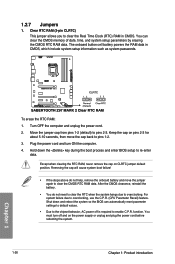
...• You do not help, remove the onboard battery and move the cap back to enable C.P.R. The onboard button cell battery powers the RAM data in CMOS. Plug the power cord and turn off is required to pins 1-2. 3. For system failure due to pins 2-3. You must... turn ON the computer. 4. 1.2.7 Jumpers 1. function. To erase the RTC RAM: 1. Move the jumper cap from pins 1-2 (default) to overclocking, use the C.P.R. (CPU Parameter Recall) feature. Removing the cap will cause system boot failure...
...• You do not help, remove the onboard battery and move the cap back to enable C.P.R. The onboard button cell battery powers the RAM data in CMOS. Plug the power cord and turn off is required to pins 1-2. 3. For system failure due to pins 2-3. You must... turn ON the computer. 4. 1.2.7 Jumpers 1. function. To erase the RTC RAM: 1. Move the jumper cap from pins 1-2 (default) to overclocking, use the C.P.R. (CPU Parameter Recall) feature. Removing the cap will cause system boot failure...
User Guide
Page 70
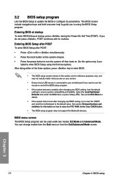
... the reset button on the system chassis. • Press the power button to turn the system off then back on how to erase the RTC RAM via the Clear CMOS button. • The BIOS setup program does not support the Bluetooth devices. Chapter 3 3-2 Chapter 3: BIOS setup
... the reset button on the system chassis. • Press the power button to turn the system off then back on how to erase the RTC RAM via the Clear CMOS button. • The BIOS setup program does not support the Bluetooth devices. Chapter 3 3-2 Chapter 3: BIOS setup

User Guide
Page 80
...the screen show [Installed]. 3-12 Chapter 3: BIOS setup Chapter 3 See section Onboard buttons and switches for information on how to erase the RTC RAM via the Clear CMOS button. • The Administrator or User Password items on top of the basic system information, and allows you have forgotten ...your BIOS password, erase the CMOS Real Time Clock (RTC) RAM to set a password, these items show the default [Not Installed]. After you enter the Advanced Mode of the BIOS Setup program. Security The...
...the screen show [Installed]. 3-12 Chapter 3: BIOS setup Chapter 3 See section Onboard buttons and switches for information on how to erase the RTC RAM via the Clear CMOS button. • The Administrator or User Password items on top of the basic system information, and allows you have forgotten ...your BIOS password, erase the CMOS Real Time Clock (RTC) RAM to set a password, these items show the default [Not Installed]. After you enter the Advanced Mode of the BIOS Setup program. Security The...


