Spresso Hardware User Manual
Page 6
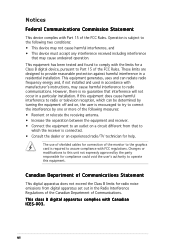
... equipment and receiver. • Connect the equipment to an outlet on a circuit different from digital apparatus set out in a residential installation. This class B digital apparatus complies with Canadian ICES-003. The use of shielded cables for help. This equipment generates, uses and can be determined by turning the equipment off and on, the user is encouraged to try...
... equipment and receiver. • Connect the equipment to an outlet on a circuit different from digital apparatus set out in a residential installation. This class B digital apparatus complies with Canadian ICES-003. The use of shielded cables for help. This equipment generates, uses and can be determined by turning the equipment off and on, the user is encouraged to try...
Spresso Hardware User Manual
Page 10
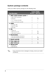
... contents Check your retailer immediately. A S U S S - Cables • AC power cable • Serial ATA cable • IDE cables 3. Documentation • User guide (Hardware Information) • User guide (Software Information) 5 . ASUS TV/FM card 8 . x Remote controller 6 . p r e s s o b a r e b o n e s y s t e m with • ASUS P4P8T motherboard • LED panel • 7-in-1 storage card reader • CPU fan and heatsink assembly 2 . Optional items • Optical drive • Hard disk drive S-presso Models S1-P111 S1-P112 X X X X X X If any of the above...
... contents Check your retailer immediately. A S U S S - Cables • AC power cable • Serial ATA cable • IDE cables 3. Documentation • User guide (Hardware Information) • User guide (Software Information) 5 . ASUS TV/FM card 8 . x Remote controller 6 . p r e s s o b a r e b o n e s y s t e m with • ASUS P4P8T motherboard • LED panel • 7-in-1 storage card reader • CPU fan and heatsink assembly 2 . Optional items • Optical drive • Hard disk drive S-presso Models S1-P111 S1-P112 X X X X X X If any of the above...
Spresso Hardware User Manual
Page 12
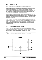
... CD/MP3 audio without entering the S-presso operating system. 1.2 Front panel (external) The S-presso front panel includes the system buttons and audio/video touch sensors, system LEDs, and LED panel. Connect external devices and peripherals with up to 3.4 GHz core frequency and up to the 4-slot card reader, audio ports, and USB ports. The S-presso S1-P111 model allows effortless control at the touch of your computing and multimedia entertainment needs. S-presso supports the Intel® Pentium® 4 processor with USB 2.0 ports, a fast Ethernet LAN port, audio ports, and...
... CD/MP3 audio without entering the S-presso operating system. 1.2 Front panel (external) The S-presso front panel includes the system buttons and audio/video touch sensors, system LEDs, and LED panel. Connect external devices and peripherals with up to 3.4 GHz core frequency and up to the 4-slot card reader, audio ports, and USB ports. The S-presso S1-P111 model allows effortless control at the touch of your computing and multimedia entertainment needs. S-presso supports the Intel® Pentium® 4 processor with USB 2.0 ports, a fast Ethernet LAN port, audio ports, and...
Spresso Hardware User Manual
Page 15
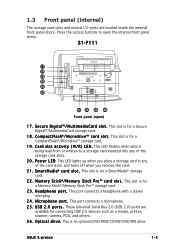
...These Universal Serial Bus 2.0 (USB 2.0) ports are located inside the internal front panel doors. O p t i c a l d r i v e . ASUS S-presso 1-5 This slot is for a Secure Digital™/MultimediaCard storage card. 1 8 . M e m o r y S t i c k®/ M e m o r y S t i c k P r o ™ c a r d s l o t . This LED flashes when data is for a Memory Stick®/Memory Stick Pro™ storage card. 2 3 . This LED lights up when you place a storage card in any of the card slots, and turns off when you remove the card. 2 1 . Press the access buttons to a storage card inserted...
...These Universal Serial Bus 2.0 (USB 2.0) ports are located inside the internal front panel doors. O p t i c a l d r i v e . ASUS S-presso 1-5 This slot is for a Secure Digital™/MultimediaCard storage card. 1 8 . M e m o r y S t i c k®/ M e m o r y S t i c k P r o ™ c a r d s l o t . This LED flashes when data is for a Memory Stick®/Memory Stick Pro™ storage card. 2 3 . This LED lights up when you place a storage card in any of the card slots, and turns off when you remove the card. 2 1 . Press the access buttons to a storage card inserted...
Spresso Hardware User Manual
Page 16
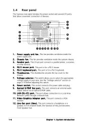
... external audio output device via an optical S/PDIF cable. 1 0 . This port allows connection to the chassis. 7 . This thumbscrew secures the top cover to a Local Area Network (LAN) through a network hub. 1 1 . V o l t a g e s e l e c t o r . In 4/6-channel mode, the function of devices. 6 1 7 8 2 3 9 4 10 5 11 12 13 14 15 16 17 18 1 . P S / 2 m o u s e p o r t . L i n e O u t p o r t ( l i m e ) . This port connects a headphone or a speaker. This switch allows you to select the appropriate voltage supply in your area. 1.4 Rear panel The S-presso rear panel...
... external audio output device via an optical S/PDIF cable. 1 0 . This port allows connection to the chassis. 7 . This thumbscrew secures the top cover to a Local Area Network (LAN) through a network hub. 1 1 . V o l t a g e s e l e c t o r . In 4/6-channel mode, the function of devices. 6 1 7 8 2 3 9 4 10 5 11 12 13 14 15 16 17 18 1 . P S / 2 m o u s e p o r t . L i n e O u t p o r t ( l i m e ) . This port connects a headphone or a speaker. This switch allows you to select the appropriate voltage supply in your area. 1.4 Rear panel The S-presso rear panel...
Spresso Hardware User Manual
Page 17
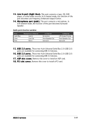
...Speaker Out Surround 1 5 . Remove this port becomes Low Frequency Enhanced Output/Center. 1 4 . This port connects a tape, CD, DVD player, or other audio sources. This port connects a microphone. These two 4-pin Universal Serial Bus 2.0 (USB 2.0) ports are available for connecting USB 2.0 devices. 1 6 . U S B 2 . 0 p o r t s . 1 3 . In 6-channel mode, the function of this cover to install an AGP card. 1 8 . In 4/6-channel mode, the function of this cover to install a PCI card. These two 4-pin Universal Serial Bus 2.0 (USB 2.0) ports are available for connecting USB...
...Speaker Out Surround 1 5 . Remove this port becomes Low Frequency Enhanced Output/Center. 1 4 . This port connects a tape, CD, DVD player, or other audio sources. This port connects a microphone. These two 4-pin Universal Serial Bus 2.0 (USB 2.0) ports are available for connecting USB 2.0 devices. 1 6 . U S B 2 . 0 p o r t s . 1 3 . In 6-channel mode, the function of this cover to install an AGP card. 1 8 . In 4/6-channel mode, the function of this cover to install a PCI card. These two 4-pin Universal Serial Bus 2.0 (USB 2.0) ports are available for connecting USB...
Spresso Hardware User Manual
Page 22
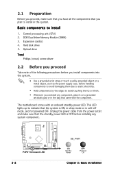
... the system. • Use a grounded wrist strap or touch a safely grounded object or a metal object, such as the power supply case, before installing any component, place it on them. • Whenever you plan to install in soft-off mode, and not powered OFF. Expansion card(s) 4. Hard disk drive 5. The motherboard comes with the component. Unplug the power cable from the power outlet and make sure that you...
... the system. • Use a grounded wrist strap or touch a safely grounded object or a metal object, such as the power supply case, before installing any component, place it on them. • Whenever you plan to install in soft-off mode, and not powered OFF. Expansion card(s) 4. Hard disk drive 5. The motherboard comes with the component. Unplug the power cable from the power outlet and make sure that you...
Spresso Hardware User Manual
Page 25
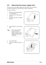
... system components. Push down the lever to hold or support it aside. Locate the lever that secures the PSU. 3. Lift up the metal tray and set it firmly. Slide the PSU out of the metal tray. ASUS S-presso 2-5 2.5 Removing the power supply unit You must remove the power supply unit (PSU) before you can install a central processing unit (CPU) and other system components. 5.
... system components. Push down the lever to hold or support it aside. Locate the lever that secures the PSU. 3. Lift up the metal tray and set it firmly. Slide the PSU out of the metal tray. ASUS S-presso 2-5 2.5 Removing the power supply unit You must remove the power supply unit (PSU) before you can install a central processing unit (CPU) and other system components. 5.

Spresso Hardware User Manual
Page 26
... installation D O N O T replace the proprietary CPU fan and heatsink with a surface mount 478-pin Zero Insertion Force (ZIF) socket. This socket is designed for an Intel® Pentium® 4 processor with up to 3.4 GHz core frequency and 800 MHz FSB. 2.6.1 Removing the CPU fan and heatsink assembly The system package includes a pre-installed proprietary CPU fan and heatsink assembly to the motherboard. 3. Using a Phillips screw driver, remove...
... installation D O N O T replace the proprietary CPU fan and heatsink with a surface mount 478-pin Zero Insertion Force (ZIF) socket. This socket is designed for an Intel® Pentium® 4 processor with up to 3.4 GHz core frequency and 800 MHz FSB. 2.6.1 Removing the CPU fan and heatsink assembly The system package includes a pre-installed proprietary CPU fan and heatsink assembly to the motherboard. 3. Using a Phillips screw driver, remove...
Spresso Hardware User Manual
Page 33
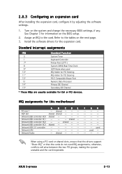
... used -- Onboard USB controller HC2 -- -- ASUS S-presso 2-13 shared -- -- -- otherwise, conflicts will arise between the two PCI groups, making the system unstable and the card inoperable. Turn on the BIOS setup. 2. Install the software drivers for this motherboard A B CDE PCI slot 1 -- used -- -- -- -- F G H -- -- -- -- -- -- -- -- -- -- -- -- -- -- -- -- -- -- -- -- When using a PCI card on the next page. 3. 2.8.3 Configuring an expansion card After installing the expansion card, configure it by adjusting the software settings...
... used -- Onboard USB controller HC2 -- -- ASUS S-presso 2-13 shared -- -- -- otherwise, conflicts will arise between the two PCI groups, making the system unstable and the card inoperable. Turn on the BIOS setup. 2. Install the software drivers for this motherboard A B CDE PCI slot 1 -- used -- -- -- -- F G H -- -- -- -- -- -- -- -- -- -- -- -- -- -- -- -- -- -- -- -- When using a PCI card on the next page. 3. 2.8.3 Configuring an expansion card After installing the expansion card, configure it by adjusting the software settings...
Spresso Hardware User Manual
Page 36
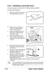
... Installing a hard disk drive The system supports one end of the 40-pin IDE cable to the IDE connector on the motherboard. Connect a 4-pin power plug from 5 the power supply unit to Master before connecting the IDE cable and power plug. Clamp HDD reverse side 4 3 5. To install a hard disk drive: 1. Refer to section "2.4 Removing the cover" for the location of the primary IDE connector. Set the hard disk drive jumper to the HDD power connector. 7. See page 3-8 for instructions. 3. Refer to the HDD documentation on how to set the hard disk drive jumper...
... Installing a hard disk drive The system supports one end of the 40-pin IDE cable to the IDE connector on the motherboard. Connect a 4-pin power plug from 5 the power supply unit to Master before connecting the IDE cable and power plug. Clamp HDD reverse side 4 3 5. To install a hard disk drive: 1. Refer to section "2.4 Removing the cover" for the location of the primary IDE connector. Set the hard disk drive jumper to the HDD power connector. 7. See page 3-8 for instructions. 3. Refer to the HDD documentation on how to set the hard disk drive jumper...
Spresso Hardware User Manual
Page 38
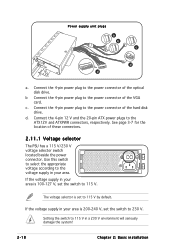
... Chapter 2: Basic installation The voltage selector is 100-127 V, set the switch to 115 V by default. Connect the 4-pin power plug to the power connector of the optical disk drive. b Connect the 4-pin power plug to the power connector of the VGA card. Power supply unit plugs a b c d d a. Connect the 4-pin 12 V and the 20-pin ATX power plugs to 115 V in your area is set to 230 V. c. See page 3-7 for the location of the hard disk drive. Connect the 4-pin power plug to 115 V. Use this switch to select the...
... Chapter 2: Basic installation The voltage selector is 100-127 V, set the switch to 115 V by default. Connect the 4-pin power plug to the power connector of the optical disk drive. b Connect the 4-pin power plug to the power connector of the VGA card. Power supply unit plugs a b c d d a. Connect the 4-pin 12 V and the 20-pin ATX power plugs to 115 V in your area is set to 230 V. c. See page 3-7 for the location of the hard disk drive. Connect the 4-pin power plug to 115 V. Use this switch to select the...

Spresso Hardware User Manual
Page 45
... RTC RAM: 1. Re-install the battery. 5. Removing the cap will cause system boot failure! Hold down the key during the boot process and enter BIOS setup to pins 2-3. 3.3 Jumper Clear RTC RAM (CLRTC) This jumper allows you clear the CMOS after first reboot. Plug the power cord and turn ON the computer. 6. Move the jumper cap from pins 1-2 (default) to re-enter data. Except when clearing the RTC RAM, never remove the cap on CLRTC jumper default position. You can clear the CMOS memory...
... RTC RAM: 1. Re-install the battery. 5. Removing the cap will cause system boot failure! Hold down the key during the boot process and enter BIOS setup to pins 2-3. 3.3 Jumper Clear RTC RAM (CLRTC) This jumper allows you clear the CMOS after first reboot. Plug the power cord and turn ON the computer. 6. Move the jumper cap from pins 1-2 (default) to re-enter data. Except when clearing the RTC RAM, never remove the cap on CLRTC jumper default position. You can clear the CMOS memory...

Spresso Hardware User Manual
Page 50
...; P4P8T Internal audio connectors 3-8 Chapter 3: Motherboard info The Ultra DMA 100/66 signal cable has three connectors: a blue connector for the primary IDE connector on the IDE connector is removed to PIN 1. SEC_IDE PRI_IDE P4P8T ® P4P8T IDE connectors PIN 1 7 . 6 . This prevents incorrect insertion when you must configure the second drive as a CD-ROM, TV tuner, or MPEG card. If you install two hard disk drives, you connect the IDE cables. • Use the...
...; P4P8T Internal audio connectors 3-8 Chapter 3: Motherboard info The Ultra DMA 100/66 signal cable has three connectors: a blue connector for the primary IDE connector on the IDE connector is removed to PIN 1. SEC_IDE PRI_IDE P4P8T ® P4P8T IDE connectors PIN 1 7 . 6 . This prevents incorrect insertion when you must configure the second drive as a CD-ROM, TV tuner, or MPEG card. If you install two hard disk drives, you connect the IDE cables. • Use the...
Spresso Hardware User Manual
Page 63
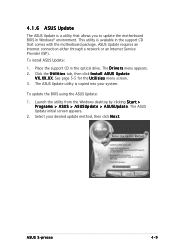
.... 2. X X . See page 5-5 for the U t i l i t i e s menu screen. 3. Place the support CD in Windows® environment. X X. The ASUS Update utility is available in the support CD that allows you to update the motherboard BIOS in the optical drive. The ASUS Update initial screen appears. 2. This utility is copied into your desired update method, then click N e x t. To install ASUS Update: 1. To update the BIOS using the ASUS Update: 1. ASUS Update requires an Internet connection either through a network or an Internet Service Provider (ISP). Select your system...
.... 2. X X . See page 5-5 for the U t i l i t i e s menu screen. 3. Place the support CD in Windows® environment. X X. The ASUS Update utility is available in the support CD that allows you to update the motherboard BIOS in the optical drive. The ASUS Update initial screen appears. 2. This utility is copied into your desired update method, then click N e x t. To install ASUS Update: 1. To update the BIOS using the ASUS Update: 1. ASUS Update requires an Internet connection either through a network or an Internet Service Provider (ISP). Select your system...

Spresso Hardware User Manual
Page 65
... change the configuration of the firmware hub. The firmware hub stores the Setup utility. Because the BIOS software is designed to make it as easy to use the Setup program, you may not exactly match what you are for reference purposes only, and may want to enable the security password feature or make changes to the power management settings. ASUS S-presso 4-11 Press during the Power-On Self Test (POST) to enter the Setup utility...
... change the configuration of the firmware hub. The firmware hub stores the Setup utility. Because the BIOS software is designed to make it as easy to use the Setup program, you may not exactly match what you are for reference purposes only, and may want to enable the security password feature or make changes to the power management settings. ASUS S-presso 4-11 Press during the Power-On Self Test (POST) to enter the Setup utility...
Spresso Hardware User Manual
Page 69
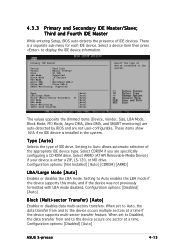
... Master While entering Setup, BIOS auto-detects the presence of device connected to the device occurs one sector at a time if the device supports multi-sector transfer feature. There is installed in the system. Configuration options: [Disabled] [Auto] ASUS S-presso 4-15 Select ARMD (ATAPI Removable Media Device) if your device is either a ZIP, LS-120, or MO drive. 4.3.3 Primary and Secondary IDE Master/Slave; Primary IDE Master Device : Hard Disk Vendor : Maxtor...
... Master While entering Setup, BIOS auto-detects the presence of device connected to the device occurs one sector at a time if the device supports multi-sector transfer feature. There is installed in the system. Configuration options: [Disabled] [Auto] ASUS S-presso 4-15 Select ARMD (ATAPI Removable Media Device) if your device is either a ZIP, LS-120, or MO drive. 4.3.3 Primary and Secondary IDE Master/Slave; Primary IDE Master Device : Hard Disk Vendor : Maxtor...

Spresso Hardware User Manual
Page 79
... Type Device #2 Emulation Type Device #3 Emulation Type Device #4 Emulation Type Device #5 Emulation Type Device #6 Emulation Type N/A [N/A] N/A [N/A] N/A [N/A] N/A [N/A] N/A [N/A] N/A [N/A] Number of seconds POST waits for example, ZIP drive). Configuration options: [10 Sec ] [20 Sec] [30 Sec] [40 Sec] Emulation Type [N/A] When set to Auto, USB devices less than 530 MB will be used to force an HDD formatted drive to boot as hard drives. The Device and Emulation Type items appear only when USB storage devices are installed. Configuration options: [Enabled] [Disabled] USB 2.0 Controller...
... Type Device #2 Emulation Type Device #3 Emulation Type Device #4 Emulation Type Device #5 Emulation Type Device #6 Emulation Type N/A [N/A] N/A [N/A] N/A [N/A] N/A [N/A] N/A [N/A] N/A [N/A] Number of seconds POST waits for example, ZIP drive). Configuration options: [10 Sec ] [20 Sec] [30 Sec] [40 Sec] Emulation Type [N/A] When set to Auto, USB devices less than 530 MB will be used to force an HDD formatted drive to boot as hard drives. The Device and Emulation Type items appear only when USB storage devices are installed. Configuration options: [Enabled] [Disabled] USB 2.0 Controller...
Spresso Hardware User Manual
Page 94
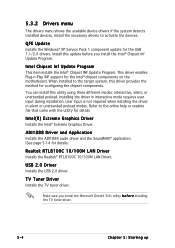
... 9.0c utility b e f o r e installing the TV tuner driver. 5-4 Chapter 5: Starting up Refer to activate the devices. QFE Update Installs the Windows® XP Service Pack 1 component update for the Intel® chipset components on the motherboard. This driver enables Plug-n-Play INF support for the USB 1.1/2.0 drivers. ADI1888 Driver and Application Installs the ADI1888 audio driver and the SoundMAX® application. |See page 5-14 for details Intel(R) Extreme Graphics Driver Installs the Intel® Extreme Graphics Driver.
... 9.0c utility b e f o r e installing the TV tuner driver. 5-4 Chapter 5: Starting up Refer to activate the devices. QFE Update Installs the Windows® XP Service Pack 1 component update for the Intel® chipset components on the motherboard. This driver enables Plug-n-Play INF support for the USB 1.1/2.0 drivers. ADI1888 Driver and Application Installs the ADI1888 audio driver and the SoundMAX® application. |See page 5-14 for details Intel(R) Extreme Graphics Driver Installs the Intel® Extreme Graphics Driver.
Spresso Hardware User Manual
Page 104
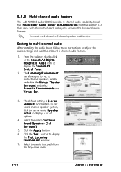
... u s t i c E n v i r o n m e n t s and Virtual Ear. 3. Select the audio test path from the support CD that came with the motherboard package to adjust the audio settings and avail the onboard 6-channel audio feature. 1. You must use 4-channel or 6-channel speakers for this setup. Click the A p p l y button. 6. The default setting is S t e r e o S p e a k e r s (2-channel). Setting to multi-channel audio After installing the audio driver, follow these instructions to activate the 6-channel audio feature. Select the option S u r r o u n d Sound Speakers (5.1 S u r r o u n d ). 5.
... u s t i c E n v i r o n m e n t s and Virtual Ear. 3. Select the audio test path from the support CD that came with the motherboard package to adjust the audio settings and avail the onboard 6-channel audio feature. 1. You must use 4-channel or 6-channel speakers for this setup. Click the A p p l y button. 6. The default setting is S t e r e o S p e a k e r s (2-channel). Setting to multi-channel audio After installing the audio driver, follow these instructions to activate the 6-channel audio feature. Select the option S u r r o u n d Sound Speakers (5.1 S u r r o u n d ). 5.


