
Spresso Hardware User Manual
Page 3
... 1-2 1.3 Front panel (internal 1-5 1.4 Rear panel 1-6 1.5 Internal components 1-8 1.6 LED panel 1-9 Chapter 2: Basic installation 2.1 Preparation 2-2 2.2 Before you proceed 2-2 2.3 Removing the front panel 2-3 2.4 Removing the cover 2-4 2.5 Removing the power supply unit 2-5 2.6 Installing a CPU 2-6 2.6.1 Removing the CPU fan and heatsink assembly ....... 2-6 2.6.2 CPU installation 2-7 2.6.3 Reinstalling the CPU fan and heatsink assembly 2-8 2.7 Installing a DIMM 2-9 2.7.1 Memory configurations 2-9 2.7.2 DIMM...
... 1-2 1.3 Front panel (internal 1-5 1.4 Rear panel 1-6 1.5 Internal components 1-8 1.6 LED panel 1-9 Chapter 2: Basic installation 2.1 Preparation 2-2 2.2 Before you proceed 2-2 2.3 Removing the front panel 2-3 2.4 Removing the cover 2-4 2.5 Removing the power supply unit 2-5 2.6 Installing a CPU 2-6 2.6.1 Removing the CPU fan and heatsink assembly ....... 2-6 2.6.2 CPU installation 2-7 2.6.3 Reinstalling the CPU fan and heatsink assembly 2-8 2.7 Installing a DIMM 2-9 2.7.1 Memory configurations 2-9 2.7.2 DIMM...
Spresso Hardware User Manual
Page 4
...Power supply specifications 2-19 Replacing the cover 2-20 Connecting external devices 2-21 Chapter 3: Motherboard info 3.1 Introduction 3-2 3.2 Motherboard layout 3-2 3.3 Jumper 3-3 3.4 Connectors 3-4 Chapter 4: BIOS information 4.1 Managing and updating your BIOS 4-2 4.1.1 Creating a bootable floppy disk 4-2 4.1.2 Using AFUDOS to copy the current BIOS 4-3 4.1.3 Using AFUDOS to update the BIOS 4-4 4.1.4 Using ASUS... EZ Flash to update the BIOS 4-6 4.1.5 Recovering the BIOS with CrashFree BIOS 2 4-7 4.1.6 ASUS Update 4-9 4.2 BIOS Setup program...
...Power supply specifications 2-19 Replacing the cover 2-20 Connecting external devices 2-21 Chapter 3: Motherboard info 3.1 Introduction 3-2 3.2 Motherboard layout 3-2 3.3 Jumper 3-3 3.4 Connectors 3-4 Chapter 4: BIOS information 4.1 Managing and updating your BIOS 4-2 4.1.1 Creating a bootable floppy disk 4-2 4.1.2 Using AFUDOS to copy the current BIOS 4-3 4.1.3 Using AFUDOS to update the BIOS 4-4 4.1.4 Using ASUS... EZ Flash to update the BIOS 4-6 4.1.5 Recovering the BIOS with CrashFree BIOS 2 4-7 4.1.6 ASUS Update 4-9 4.2 BIOS Setup program...

Spresso Hardware User Manual
Page 5
... Configuration 4-18 4.4.2 Chipset 4-19 4.4.3 Onboard Devices Configuration 4-21 4.4.4 PCI PnP 4-23 4.4.5 USB Configuration 4-24 4.5 Power menu 4-26 4.5.1 Suspend Mode 4-26 4.5.2 Repost Video on S3 Resume 4-26 4.5.3 ACPI 2.0 Support 4-26 4.5.4 ACPI... 5: Starting up 5.2 Powering up 5-2 5.1 Installing an operating system 5-2 5.3 Support CD information 5-3 5.3.1 Running the support CD 5-3 5.3.2 Drivers menu 5-4 5.3.3 Utilities menu 5-5 5.3.4 ASUS contact information 5-6 5.3.5 Other information 5-6 5.4 Software information 5-8 5.4.1 ASUS Update 5-8 5.4.2 ASUS PC Probe 5-10 5.4.3...
... Configuration 4-18 4.4.2 Chipset 4-19 4.4.3 Onboard Devices Configuration 4-21 4.4.4 PCI PnP 4-23 4.4.5 USB Configuration 4-24 4.5 Power menu 4-26 4.5.1 Suspend Mode 4-26 4.5.2 Repost Video on S3 Resume 4-26 4.5.3 ACPI 2.0 Support 4-26 4.5.4 ACPI... 5: Starting up 5.2 Powering up 5-2 5.1 Installing an operating system 5-2 5.3 Support CD information 5-3 5.3.1 Running the support CD 5-3 5.3.2 Drivers menu 5-4 5.3.3 Utilities menu 5-5 5.3.4 ASUS contact information 5-6 5.3.5 Other information 5-6 5.4 Software information 5-8 5.4.1 ASUS Update 5-8 5.4.2 ASUS PC Probe 5-10 5.4.3...
Spresso Hardware User Manual
Page 7
... Austausch der Batterie. Operation safety • Before installing devices into the system, carefully read all cables are correctly connected and the power cables are not damaged. Do not place the product in any damage, contact your dealer immediately. • To avoid short circuits...become wet. LASER PRODUCT WARNING CLASS 1 LASER PRODUCT vii Safety information Electrical safety • To prevent electrical shock hazard, disconnect the power cable from the electrical outlet before relocating the system. • When adding or removing devices to or from connectors, slots, sockets and...
... Austausch der Batterie. Operation safety • Before installing devices into the system, carefully read all cables are correctly connected and the power cables are not damaged. Do not place the product in any damage, contact your dealer immediately. • To avoid short circuits...become wet. LASER PRODUCT WARNING CLASS 1 LASER PRODUCT vii Safety information Electrical safety • To prevent electrical shock hazard, disconnect the power cable from the electrical outlet before relocating the system. • When adding or removing devices to or from connectors, slots, sockets and...
Spresso Hardware User Manual
Page 8
...this guide Audience This guide provides general information and installation instructions about the P4P8T motherboard that comes with hardware knowledge of the ASUS S-presso. The chapter lists the system features including introduction on how to change system settings through the BIOS Setup menus and describes the... BIOS parameters. 5. Chapter 5: Starting Up This chapter helps you power up the system and install drivers and utilities from the support CD. This guide is organized 1. Chapter 2: Basic Installation This...
...this guide Audience This guide provides general information and installation instructions about the P4P8T motherboard that comes with hardware knowledge of the ASUS S-presso. The chapter lists the system features including introduction on how to change system settings through the BIOS Setup menus and describes the... BIOS parameters. 5. Chapter 5: Starting Up This chapter helps you power up the system and install drivers and utilities from the support CD. This guide is organized 1. Chapter 2: Basic Installation This...
Spresso Hardware User Manual
Page 10
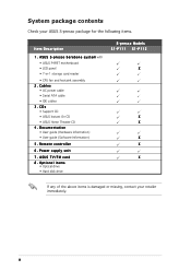
... • ASUS Home Theater CD 4 . Power supply unit 7 . ASUS TV/FM card 8 . p r e s s o b a r e b o n e s y s t e m with • ASUS P4P8T motherboard • LED panel • 7-in-1 storage card reader • CPU fan and heatsink assembly 2 . x Documentation • User guide (Hardware Information) • User guide (Software Information) 5 . Remote controller 6 . A S U S S - Optional items • Optical drive • Hard disk drive S-presso Models...
... • ASUS Home Theater CD 4 . Power supply unit 7 . ASUS TV/FM card 8 . p r e s s o b a r e b o n e s y s t e m with • ASUS P4P8T motherboard • LED panel • 7-in-1 storage card reader • CPU fan and heatsink assembly 2 . x Documentation • User guide (Hardware Information) • User guide (Software Information) 5 . Remote controller 6 . A S U S S - Optional items • Optical drive • Hard disk drive S-presso Models...
Spresso Hardware User Manual
Page 12
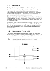
...Powered by the ASUS P4P8T motherboard, S-presso delivers robust technology for choosing the ASUS S-presso Multimedia System! Connect external devices and peripherals with its touch sensor control panel and LED display. 1.1 Welcome! The front panel doors give you to enjoy DVD/DVD movies and stereo quality CD/MP3 audio without entering the S-presso...fast Ethernet LAN port, audio ports, and an S/PDIF Out interface. The ASUS S-presso is a smart personal computer and a versatile home entertainment system in one. S-presso supports the Intel® Pentium® 4 processor with up to 3.4 ...
...Powered by the ASUS P4P8T motherboard, S-presso delivers robust technology for choosing the ASUS S-presso Multimedia System! Connect external devices and peripherals with its touch sensor control panel and LED display. 1.1 Welcome! The front panel doors give you to enjoy DVD/DVD movies and stereo quality CD/MP3 audio without entering the S-presso...fast Ethernet LAN port, audio ports, and an S/PDIF Out interface. The ASUS S-presso is a smart personal computer and a versatile home entertainment system in one. S-presso supports the Intel® Pentium® 4 processor with up to 3.4 ...
Spresso Hardware User Manual
Page 13
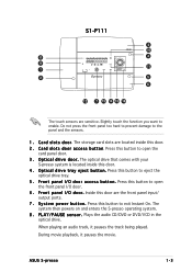
... CD/DVD or DVD/VCD in the optical drive. The storage card slots are the front panel input/ output ports. 7 . The system then powers on and enters the S-presso operating system. 8 . O p t i c a l d r i v e d o o r . S y s t e m p o w e r b u t t o n . Press this door. 2 . Press this button to enable. Press this button to open the card ... exit Instant On. S1-P111 3 10 8 4 9 11 1 2 5 6 12 7 13 14 15 16 The touch sensors are sensitive. F r o n t p a n e l I / O d o o r a c c e s s b u t t o n . ASUS S-presso 1-3 C a r d s l o t s d o o r a c c e s s b u t t o n.
... CD/DVD or DVD/VCD in the optical drive. The storage card slots are the front panel input/ output ports. 7 . The system then powers on and enters the S-presso operating system. 8 . O p t i c a l d r i v e d o o r . S y s t e m p o w e r b u t t o n . Press this door. 2 . Press this button to enable. Press this button to open the card ... exit Instant On. S1-P111 3 10 8 4 9 11 1 2 5 6 12 7 13 14 15 16 The touch sensors are sensitive. F r o n t p a n e l I / O d o o r a c c e s s b u t t o n . ASUS S-presso 1-3 C a r d s l o t s d o o r a c c e s s b u t t o n.
Spresso Hardware User Manual
Page 16
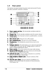
... cable. 1 0 . This port allows connection to select the appropriate voltage supply in your area. 1.4 Rear panel The S-presso rear panel includes the power socket and several I F O u t p o r t . P S / 2 m o u s e p.... C h a s s i s f a n . P a r a l l e l p o r t . See the "Voltage selector" section on page 2-18 before adjusting this port becomes Front Speaker Out. 1-6 Chapter 1: System introduction This socket connects the power cable and plug. 9 . L i n e O u t p o r t ( l i m e ) . P S / 2 k e y b o a r d p o r t . This thumbscrew secures the top cover to the chassis. 7 ....
... cable. 1 0 . This port allows connection to select the appropriate voltage supply in your area. 1.4 Rear panel The S-presso rear panel includes the power socket and several I F O u t p o r t . P S / 2 m o u s e p.... C h a s s i s f a n . P a r a l l e l p o r t . See the "Voltage selector" section on page 2-18 before adjusting this port becomes Front Speaker Out. 1-6 Chapter 1: System introduction This socket connects the power cable and plug. 9 . L i n e O u t p o r t ( l i m e ) . P S / 2 k e y b o a r d p o r t . This thumbscrew secures the top cover to the chassis. 7 ....
Spresso Hardware User Manual
Page 20
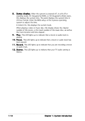
...well as the track duration and time elapsed . 9 . P a u s e . 8 . This LED lights up to adjust the time. When the system is powered off or stand-by mode, S3 (Suspend-to-RAM), or S4 (Suspend-to indicate that you are recording a movie or audio track. 1 2 . This LED lights... up to -Disk) state, this displays the system time. Enter the BIOS setup or the S-presso operating system to indicate that your TV audio setting is playing. 1 0 . S t e r e o . R e c o r d . When playing a video or music disc, this displays ...
...well as the track duration and time elapsed . 9 . P a u s e . 8 . This LED lights up to adjust the time. When the system is powered off or stand-by mode, S3 (Suspend-to-RAM), or S4 (Suspend-to indicate that you are recording a movie or audio track. 1 2 . This LED lights... up to -Disk) state, this displays the system time. Enter the BIOS setup or the S-presso operating system to indicate that your TV audio setting is playing. 1 0 . S t e r e o . R e c o r d . When playing a video or music disc, this displays ...
Spresso Hardware User Manual
Page 22
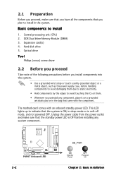
...components into the system. • Use a grounded wrist strap or touch a safely grounded object or a metal object, such as the power supply case, before handling components to avoid damaging them due to static electricity. • Hold components by the edges to avoid touching the...P4P8T ® P4P8T Onboard LED 2-2 SB_PWR ON Standby Power OFF Powered Off Chapter 2: Basic installation This LED lights up to indicate that came with an onboard standby power LED. Basic components to install 1. Unplug the power cable from the power outlet and make sure that you have all the ...
...components into the system. • Use a grounded wrist strap or touch a safely grounded object or a metal object, such as the power supply case, before handling components to avoid damaging them due to static electricity. • Hold components by the edges to avoid touching the...P4P8T ® P4P8T Onboard LED 2-2 SB_PWR ON Standby Power OFF Powered Off Chapter 2: Basic installation This LED lights up to indicate that came with an onboard standby power LED. Basic components to install 1. Unplug the power cable from the power outlet and make sure that you have all the ...
Spresso Hardware User Manual
Page 23
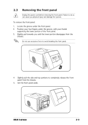
... panel Unplug the power cord before removing the front panel. Failure to completely release the front panel from the chassis. To remove the front panel: 1. Position your four fingers under the front panel. 2. Set the front panel aside. Slightly pull towards you physical injury and damage the system. ASUS S-presso 2-3 Locate the groove...
... panel Unplug the power cord before removing the front panel. Failure to completely release the front panel from the chassis. To remove the front panel: 1. Position your four fingers under the front panel. 2. Set the front panel aside. Slightly pull towards you physical injury and damage the system. ASUS S-presso 2-3 Locate the groove...
Spresso Hardware User Manual
Page 25
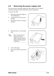
... secures the PSU. 3. Push down the lever to hold or support it aside. ASUS S-presso 2-5 When removing the PSU, make sure to release the PSU. 4. 2.5 Removing the power supply unit You must remove the power supply unit (PSU) before you can install a central processing unit (CPU) and other... system components. 5. To remove the PSU: 1. Set the PSU aside. 6. Slide the PSU out of the metal tray. Disconnect the power plugs on the motherboard...
... secures the PSU. 3. Push down the lever to hold or support it aside. ASUS S-presso 2-5 When removing the PSU, make sure to release the PSU. 4. 2.5 Removing the power supply unit You must remove the power supply unit (PSU) before you can install a central processing unit (CPU) and other... system components. 5. To remove the PSU: 1. Set the PSU aside. 6. Slide the PSU out of the metal tray. Disconnect the power plugs on the motherboard...
Spresso Hardware User Manual
Page 31
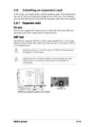
The P4P8T motherboard does not support 3.3V AGP cards. Unplug the power cord before adding or removing expansion cards. AGP slot The AGP slot supports AGP 8X (+0.8V) cards and AGP 4X (+1.5V) cards. 2.8 Installing an expansion ... injury and damage the motherboard. P4P8T ® P4P8T Accelerated Graphics Port (AGP) Keyed for one Accelerated Graphics Port (AGP) slot. When you ask for 1.5v ASUS S-presso 2-11 Failure to do so can cause you might need to install expansion cards. The following sub-sections describe the slots and the expansion cards...
The P4P8T motherboard does not support 3.3V AGP cards. Unplug the power cord before adding or removing expansion cards. AGP slot The AGP slot supports AGP 8X (+0.8V) cards and AGP 4X (+1.5V) cards. 2.8 Installing an expansion ... injury and damage the motherboard. P4P8T ® P4P8T Accelerated Graphics Port (AGP) Keyed for one Accelerated Graphics Port (AGP) slot. When you ask for 1.5v ASUS S-presso 2-11 Failure to do so can cause you might need to install expansion cards. The following sub-sections describe the slots and the expansion cards...
Spresso Hardware User Manual
Page 34
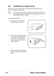
..." for instructions. 3. Remove the front panel. Slide the optical drive into place. 2-14 Chapter 2: Basic installation Refer to Master before connecting the IDE cable and power plug. Refer to this section to the optical drive documentation on each side of the optical drive as shown. 2. Drive a screw on how to set... install an optical drive: 1. Push the optical drive until the hinge lock snaps the screws into the optical drive bay. 4. 2.9 Installing an optical drive The S-presso system comes with one optical drive bay.
..." for instructions. 3. Remove the front panel. Slide the optical drive into place. 2-14 Chapter 2: Basic installation Refer to Master before connecting the IDE cable and power plug. Refer to this section to the optical drive documentation on each side of the optical drive as shown. 2. Drive a screw on how to set... install an optical drive: 1. Push the optical drive until the hinge lock snaps the screws into the optical drive bay. 4. 2.9 Installing an optical drive The S-presso system comes with one optical drive bay.
Spresso Hardware User Manual
Page 35
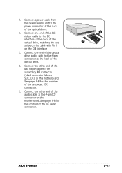
... from the power supply unit to the power connector at the back of the IDE ribbon cable to the IDE interface at the back of the optical drive, matching the red stripe on the cable with Pin 1 on the motherboard. See page 3-8 for the location of the CD audio connector. 5 6 7 ASUS S-presso 2-15 Connect...
... from the power supply unit to the power connector at the back of the IDE ribbon cable to the IDE interface at the back of the optical drive, matching the red stripe on the cable with Pin 1 on the motherboard. See page 3-8 for the location of the CD audio connector. 5 6 7 ASUS S-presso 2-15 Connect...
Spresso Hardware User Manual
Page 36
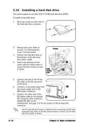
...HDD reverse side 4 3 5. Connect one Ultra ATA/133 IDE hard disk drive (HDD). Connect a 4-pin power plug from 5 the power supply unit to Master before connecting the IDE cable and power plug. Position the hard disk drive at the bottom of the hard disk drive as shown. 2. Connect the ... connector labeled PRI_IDE) on the drive. 6. Remove the cover. See page 3-8 for instructions. 3. Set the hard disk drive jumper to the HDD power connector. 7. Refer to the HDD documentation on how to set the hard disk drive jumper to section "2.4 Removing the cover" for the location of ...
...HDD reverse side 4 3 5. Connect one Ultra ATA/133 IDE hard disk drive (HDD). Connect a 4-pin power plug from 5 the power supply unit to Master before connecting the IDE cable and power plug. Position the hard disk drive at the bottom of the hard disk drive as shown. 2. Connect the ... connector labeled PRI_IDE) on the drive. 6. Remove the cover. See page 3-8 for instructions. 3. Set the hard disk drive jumper to the HDD power connector. 7. Refer to the HDD documentation on how to set the hard disk drive jumper to section "2.4 Removing the cover" for the location of ...
Spresso Hardware User Manual
Page 37
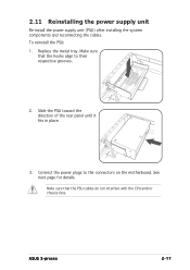
Replace the metal tray. See next page for details. Connect the power plugs to their respective grooves. 2. Make sure that the PSU cables do not interfere with the CPU and/or chassis fans. Make sure that the hooks align to the connectors on the motherboard. 2.11 Reinstalling the power supply unit Re-install the power supply unit (PSU) after installing the system components and reconnecting the cables. Slide the PSU toward the direction of the rear panel until it fits in place. 3. ASUS S-presso 2-17 To reinstall the PSU: 1.
Replace the metal tray. See next page for details. Connect the power plugs to their respective grooves. 2. Make sure that the PSU cables do not interfere with the CPU and/or chassis fans. Make sure that the hooks align to the connectors on the motherboard. 2.11 Reinstalling the power supply unit Re-install the power supply unit (PSU) after installing the system components and reconnecting the cables. Slide the PSU toward the direction of the rear panel until it fits in place. 3. ASUS S-presso 2-17 To reinstall the PSU: 1.
Spresso Hardware User Manual
Page 38
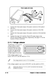
... Setting the switch to the ATX12V and ATXPWR connectors, respectively. Power supply unit plugs a b c d d a. d. Connect the 4-pin 12 V and the 20-pin ATX power plugs to 115 V in your area is 100-127 V, set the switch to the power connector of the optical disk drive. If the voltage supply in... your area is set the switch to the power connector of the VGA card. Connect the 4-pin power plug to 230 V. c. Connect the 4-pin power plug to the voltage supply in your area. Use this switch to select the appropriate voltage ...
... Setting the switch to the ATX12V and ATXPWR connectors, respectively. Power supply unit plugs a b c d d a. d. Connect the 4-pin 12 V and the 20-pin ATX power plugs to 115 V in your area is 100-127 V, set the switch to the power connector of the optical disk drive. If the voltage supply in... your area is set the switch to the power connector of the VGA card. Connect the 4-pin power plug to 230 V. c. Connect the 4-pin power plug to the voltage supply in your area. Use this switch to select the appropriate voltage ...
Spresso Hardware User Manual
Page 39
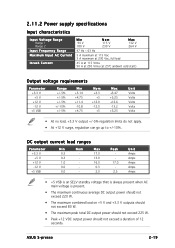
...; At +12 V surge, regulation can go up to +/-10%. DC output current load ranges Parameter +3.3 V +5 V +12 V -12 V +5 VSB Min 0.5 0.3 1.0 0.0 0.0 Nom - ASUS S-presso 2-19 Max 17.0 13.0 16.0 0.3 2.0 Peak - 17.0 - 2.5 Unit Amps Amps Amps Amps Amps • +5 VSB is an SELV standby voltage that is always present when... AC main voltage is present. • The maximum continuous average DC output power should not exceed 220 W. • The maximum combined load on +5 V and +3.3 V outputs should not exceed 80 W. • The maximum peak...
...; At +12 V surge, regulation can go up to +/-10%. DC output current load ranges Parameter +3.3 V +5 V +12 V -12 V +5 VSB Min 0.5 0.3 1.0 0.0 0.0 Nom - ASUS S-presso 2-19 Max 17.0 13.0 16.0 0.3 2.0 Peak - 17.0 - 2.5 Unit Amps Amps Amps Amps Amps • +5 VSB is an SELV standby voltage that is always present when... AC main voltage is present. • The maximum continuous average DC output power should not exceed 220 W. • The maximum combined load on +5 V and +3.3 V outputs should not exceed 80 W. • The maximum peak...


