RS720-E7-RS24-EG User's Manual
Page 15
With the correct serial number of the product's serial number containing 14 characters such as xxS0xxxxxxxxxx shown as the figure below. 1.2 Serial number label Before requesting support from the ASUS Technical Support team, you must take note of the product, ASUS Technical Support team members can then offer a quicker and satisfying solution to your problems. RS720-E7-RS24-EG xxS0xxxxxxxxxx ASUS RS720-E7-RS24-EG 1-3
With the correct serial number of the product's serial number containing 14 characters such as xxS0xxxxxxxxxx shown as the figure below. 1.2 Serial number label Before requesting support from the ASUS Technical Support team, you must take note of the product, ASUS Technical Support team members can then offer a quicker and satisfying solution to your problems. RS720-E7-RS24-EG xxS0xxxxxxxxxx ASUS RS720-E7-RS24-EG 1-3
RS720-E7-RS24-EG User's Manual
Page 16
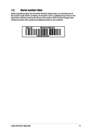
... Slot Location 2 Slots (follow Slot Location 3 SSI Location #) Slot Location 4 Slot Location 6 Additional Slot 1 Networking LAN Storage SATA Controller SAS Controller RS720-E7-RS24-EG 2 x Socket LGA 2011 Intel® Xeon® processor E5-2600 / E5-2600 V2 product family QPI 6.4 /7.2 / 8.0 GT/s Intel®... 2208, or PIKE 2308. * Refer to www.asus.com for the complete list of supported memory modules. (continued on the next page) 1-4 Chapter 1: Product introduction x 13 in . 1.3 System specifications The ASUS RS720-E7-RS24-EG is a 2U barebone server system featuring the Z9PE-...
... Slot Location 2 Slots (follow Slot Location 3 SSI Location #) Slot Location 4 Slot Location 6 Additional Slot 1 Networking LAN Storage SATA Controller SAS Controller RS720-E7-RS24-EG 2 x Socket LGA 2011 Intel® Xeon® processor E5-2600 / E5-2600 V2 product family QPI 6.4 /7.2 / 8.0 GT/s Intel®... 2208, or PIKE 2308. * Refer to www.asus.com for the complete list of supported memory modules. (continued on the next page) 1-4 Chapter 1: Product introduction x 13 in . 1.3 System specifications The ASUS RS720-E7-RS24-EG is a 2U barebone server system featuring the Z9PE-...
RS720-E7-RS24-EG User's Manual
Page 17
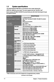
.../2 Mouse Software Management Out of Band Solution Remote Management Dimension (HH x WW x DD) Net Weight Kg (CPU, DRAM, and HDD not inclu ded) Power Supply RS720-E7-RS24-EG 24 x Hot-swap 2.5-inch HDD bays 2 x Hot-swap 2.5-inch HDD bays (Rear) Aspeed AST2300 16MB 1 1 x USB connector (Type A USB socket) 2 x USB pin header (up to... I = Internal A or S will be hotswappable VGA TPM Header USB Connectors Onboard I/O Connectors Rear I Environment Power supply rating and configuration may vary depending on the region. ASUS RS720-E7-RS24-EG 1-5
.../2 Mouse Software Management Out of Band Solution Remote Management Dimension (HH x WW x DD) Net Weight Kg (CPU, DRAM, and HDD not inclu ded) Power Supply RS720-E7-RS24-EG 24 x Hot-swap 2.5-inch HDD bays 2 x Hot-swap 2.5-inch HDD bays (Rear) Aspeed AST2300 16MB 1 1 x USB connector (Type A USB socket) 2 x USB pin header (up to... I = Internal A or S will be hotswappable VGA TPM Header USB Connectors Onboard I/O Connectors Rear I Environment Power supply rating and configuration may vary depending on the region. ASUS RS720-E7-RS24-EG 1-5

RS720-E7-RS24-EG User's Manual
Page 19
... drive drive. SATA backplane (hidden) 5. Connect a USB floppy disk drive to use a floppy disk. *WARNING HAZARDOUS MOVING PARTS KEEP FINGERS AND OTHER BODY PARTS AWAY ASUS RS720-E7-RS24-EG 1-7 Asset Tag (hidden) 8 5 6 Turn off the system power and detach the power supply before removing or replacing any of the USB ports on the front...
... drive drive. SATA backplane (hidden) 5. Connect a USB floppy disk drive to use a floppy disk. *WARNING HAZARDOUS MOVING PARTS KEEP FINGERS AND OTHER BODY PARTS AWAY ASUS RS720-E7-RS24-EG 1-7 Asset Tag (hidden) 8 5 6 Turn off the system power and detach the power supply before removing or replacing any of the USB ports on the front...
RS720-E7-RS24-EG User's Manual
Page 21
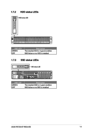
1.7.2 HDD status LEDs HDD status LED 2 1 2 1 HDD LED GREEN OFF Description The installed HDD is in good condition SSD failure or no HDD is installed 1.7.3 SSD status LEDs SSD status LED SSD LED GREEN OFF Description The installed SSD is in good condition SSD failure or no SSD is installed ASUS RS720-E7-RS24-EG 1-9
1.7.2 HDD status LEDs HDD status LED 2 1 2 1 HDD LED GREEN OFF Description The installed HDD is in good condition SSD failure or no HDD is installed 1.7.3 SSD status LEDs SSD status LED SSD LED GREEN OFF Description The installed SSD is in good condition SSD failure or no SSD is installed ASUS RS720-E7-RS24-EG 1-9
RS720-E7-RS24-EG User's Manual
Page 25
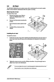
... the instructions. 2 2. Installing the air duct To install the air duct: 1. Tighten the screws one by one with a motherboard fan air duct to the motherboard. ASUS RS720-E7-RS24 Series 2-3 Removing the air duct To remove the air duct: 1. Carefully lift the air duct out of the motherboard matching the three (3) screw holes on...; Ensure that the air duct is firmly fitted to enable better air flow inside the motherboard while the system is running. 2.2 Air Duct The RS740-E7-RS24-EG server system comes with a Phillips screwdriver. A B A C B C 2.
... the instructions. 2 2. Installing the air duct To install the air duct: 1. Tighten the screws one by one with a motherboard fan air duct to the motherboard. ASUS RS720-E7-RS24 Series 2-3 Removing the air duct To remove the air duct: 1. Carefully lift the air duct out of the motherboard matching the three (3) screw holes on...; Ensure that the air duct is firmly fitted to enable better air flow inside the motherboard while the system is running. 2.2 Air Duct The RS740-E7-RS24-EG server system comes with a Phillips screwdriver. A B A C B C 2.
RS720-E7-RS24-EG User's Manual
Page 27
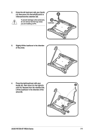
To prevent damage to the right (D) until it is A released from the retention tab. ASUS RS720-E7-RS24 Series E C D 2-5 Slightly lift the load lever in the direction of the arrow. 4. Lift the load lever in the direction of the arrow (E). 2. Press the right load lever with your thumb (C), then move it to the left load lever with your thumb (A), then move it to the socket pins, do not remove the PnP cap unless you are installing a CPU. Press the left (B) until it is released from the retention tab. B Load lever 3.
To prevent damage to the right (D) until it is A released from the retention tab. ASUS RS720-E7-RS24 Series E C D 2-5 Slightly lift the load lever in the direction of the arrow. 4. Lift the load lever in the direction of the arrow (E). 2. Press the right load lever with your thumb (C), then move it to the left load lever with your thumb (A), then move it to the socket pins, do not remove the PnP cap unless you are installing a CPU. Press the left (B) until it is released from the retention tab. B Load lever 3.
RS720-E7-RS24-EG User's Manual
Page 29
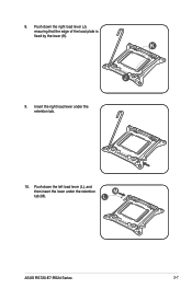
Push down the right load lever (J), ensuring that the edge of the load plate is fixed by the lever (K). L ASUS RS720-E7-RS24 Series 2-7 8. K J 9. Push down the left load lever (L), and then insert the lever under the retention tab. 10. Insert the right load lever under the retention M tab (M).
Push down the right load lever (J), ensuring that the edge of the load plate is fixed by the lever (K). L ASUS RS720-E7-RS24 Series 2-7 8. K J 9. Push down the left load lever (L), and then insert the lever under the retention tab. 10. Insert the right load lever under the retention M tab (M).

RS720-E7-RS24-EG User's Manual
Page 31
... To install the CPU heatsink: 1. Place the heatsink on top of the installed CPU, ensuring that the four screws match the holes on the motherboard. 2. ASUS RS720-E7-RS24 Series 2-9
... To install the CPU heatsink: 1. Place the heatsink on top of the installed CPU, ensuring that the four screws match the holes on the motherboard. 2. ASUS RS720-E7-RS24 Series 2-9
RS720-E7-RS24-EG User's Manual
Page 33
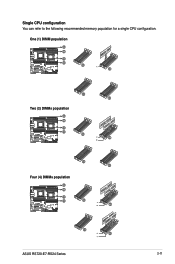
A-B Single CPU configuration A-B You can refer to the following recommended memory population for a single CPU configuration. One (1) DIMM population G-H A-B F-E D-C G-H A-B A-B A-B F-E D-C Two (2) DIMMs population G-H A-B A-B F-E D-C D-C G-H A-B A-B F-E D-C D-C Four (4) DIMMs population G-H A-B F-E D-C G-H A-B F-E D-C ASUS RS720-E7-RS24 Series 2-11
A-B Single CPU configuration A-B You can refer to the following recommended memory population for a single CPU configuration. One (1) DIMM population G-H A-B F-E D-C G-H A-B A-B A-B F-E D-C Two (2) DIMMs population G-H A-B A-B F-E D-C D-C G-H A-B A-B F-E D-C D-C Four (4) DIMMs population G-H A-B F-E D-C G-H A-B F-E D-C ASUS RS720-E7-RS24 Series 2-11
RS720-E7-RS24-EG User's Manual
Page 37
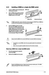
... any further to avoid damaging the DIMM. 3. The DIMM might get damaged when it fits in the motherboard package. • Refer to unlock the DIMM. 2. ASUS RS720-E7-RS24 Series 2-15 Align a DIMM on the socket such that it flips out with extra force. Hold the DIMM by pressing the DIMM notch retaining clip...
... any further to avoid damaging the DIMM. 3. The DIMM might get damaged when it fits in the motherboard package. • Refer to unlock the DIMM. 2. ASUS RS720-E7-RS24 Series 2-15 Align a DIMM on the socket such that it flips out with extra force. Hold the DIMM by pressing the DIMM notch retaining clip...
RS720-E7-RS24-EG User's Manual
Page 39
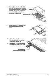
... insert the 2.5-inch Serial ATA HDD/ SAS HDD and drive tray assembly into the tray. drive tray and 2.5-inch Serial ATA HDD/SAS HDD assembly ASUS RS720-E7-RS24 Series 2-17 drive tray screw hole 5. Secure the Serial ATA HDD/ SAS HDD to install the other 2.5-inch Serial ATA HDD/ SAS HDDs. Ensure that...
... insert the 2.5-inch Serial ATA HDD/ SAS HDD and drive tray assembly into the tray. drive tray and 2.5-inch Serial ATA HDD/SAS HDD assembly ASUS RS720-E7-RS24 Series 2-17 drive tray screw hole 5. Secure the Serial ATA HDD/ SAS HDD to install the other 2.5-inch Serial ATA HDD/ SAS HDDs. Ensure that...
RS720-E7-RS24-EG User's Manual
Page 41
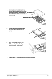
Secure the SDD to install the second SSD drive. Ensure that the four screws of SSD screw hole the SSD matches the four screw holes of SSD the drive tray. 4. drive tray screw hole 5. Repeat steps 1-6 if you want to the drive tray with four screws that is fitted firmly inside the drive tray and that the SSD is bundled with the server. 6. ASUS RS720-E7-RS24 Series 2-19 Align and insert the drive tray and SSD assembly into the tray. Orient and place the SSD into the drive bay until it is securely fitted in place. 7.
Secure the SDD to install the second SSD drive. Ensure that the four screws of SSD screw hole the SSD matches the four screw holes of SSD the drive tray. 4. drive tray screw hole 5. Repeat steps 1-6 if you want to the drive tray with four screws that is fitted firmly inside the drive tray and that the SSD is bundled with the server. 6. ASUS RS720-E7-RS24 Series 2-19 Align and insert the drive tray and SSD assembly into the tray. Orient and place the SSD into the drive bay until it is securely fitted in place. 7.
RS720-E7-RS24-EG User's Manual
Page 43
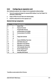
... Chapter 5 for information on the system and change the necessary BIOS settings, if any. Standard Interrupt assignments IRQ Priority Standard function 0 1 System Timer 1 2 Keyboard Controller 2 - ASUS RS720-E7-RS24 Series 2-21 2.6.2 Configuring an expansion card After installing the expansion card, configure the it by adjusting the software settings. 1. Assign an IRQ to the following...
... Chapter 5 for information on the system and change the necessary BIOS settings, if any. Standard Interrupt assignments IRQ Priority Standard function 0 1 System Timer 1 2 Keyboard Controller 2 - ASUS RS720-E7-RS24 Series 2-21 2.6.2 Configuring an expansion card After installing the expansion card, configure the it by adjusting the software settings. 1. Assign an IRQ to the following...

RS720-E7-RS24-EG User's Manual
Page 45
A A B 3. 2.8 System fans The server have four (4) easy-swap system fans for optimum heat dissipation and efficient cooling solution. • Ensure that you want to remove. ASUS RS720-E7-RS24 Series 2-23 Prepare a replacement fan of fans. Replacing the system fan To replace a system fan: 1. Locate the front system fan that the system is turned ...
A A B 3. 2.8 System fans The server have four (4) easy-swap system fans for optimum heat dissipation and efficient cooling solution. • Ensure that you want to remove. ASUS RS720-E7-RS24 Series 2-23 Prepare a replacement fan of fans. Replacing the system fan To replace a system fan: 1. Locate the front system fan that the system is turned ...
RS720-E7-RS24-EG User's Manual
Page 47
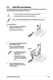
...SAS/SATA connector location. metal clip • The PIKE RAID card fits to the PIKE RAID card slot in Step 1. 3 2 ASUS RS720-E7-RS24 Series 2-25 Install an optional ASUS PIKE RAID card based on the PIKE card is firmly clamped in the motherboard's PIKE card slot. 3. Refer to section 4.3 Internal... RAID card to the motherboard using the screw that the system is completely seated on the motherboard 1 adjacent to the PIKE card slot. 2.9 ASUS PIKE card (Optional) The PIKE slot allows you to choose and change your needs. • Ensure that you removed in one orientation only....
...SAS/SATA connector location. metal clip • The PIKE RAID card fits to the PIKE RAID card slot in Step 1. 3 2 ASUS RS720-E7-RS24 Series 2-25 Install an optional ASUS PIKE RAID card based on the PIKE card is firmly clamped in the motherboard's PIKE card slot. 3. Refer to section 4.3 Internal... RAID card to the motherboard using the screw that the system is completely seated on the motherboard 1 adjacent to the PIKE card slot. 2.9 ASUS PIKE card (Optional) The PIKE slot allows you to choose and change your needs. • Ensure that you removed in one orientation only....
RS720-E7-RS24-EG User's Manual
Page 49
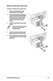
... bay, use your other hand to remove the plastic covering the power supply module before installing the module. 4. Ensure to support the power supply module. 3. A B C D ASUS RS720-E7-RS24 Series 2-27 Press the lock (C) then push the power supply module until it is securely seated in place (D). Press the lock (A) then pull the power...
... bay, use your other hand to remove the plastic covering the power supply module before installing the module. 4. Ensure to support the power supply module. 3. A B C D ASUS RS720-E7-RS24 Series 2-27 Press the lock (C) then push the power supply module until it is securely seated in place (D). Press the lock (A) then pull the power...
RS720-E7-RS24-EG User's Manual
Page 53
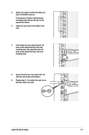
... rail with two thin lips on the bottom thin lip of the rack. Select a 2U space on the other side of the front mounting hole. 5. ASUS RS720-E7-RS24 3-3
... rail with two thin lips on the bottom thin lip of the rack. Select a 2U space on the other side of the front mounting hole. 5. ASUS RS720-E7-RS24 3-3
RS720-E7-RS24-EG User's Manual
Page 57
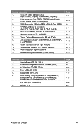
... SMBus connector (5-pin PSUSMB1) 6. Serial port connector (10-1 pin COM1) 7. ERR DIMMG1/2;ERR DIMMH1/2) 7. Q-Code LEDs Page 4-17 4-17 4-18 4-18 4-19 4-19 4-20 4-21 ASUS RS720-E7-RS24 4-3 Serial ATA 6.0/3.0 Gb/s connectors (7-pin SATA6G_1-2 [Blue]) (7-pin SATA3G_3-6 [black]) 2. PSAS connectors (7-pin PSAS1, PSAS2, PSAS3, PSAS4, PSAS5, PSAS6, PSAS7, PSAS8 [Blue]) 3. USB 2.0 connector (10...
... SMBus connector (5-pin PSUSMB1) 6. Serial port connector (10-1 pin COM1) 7. ERR DIMMG1/2;ERR DIMMH1/2) 7. Q-Code LEDs Page 4-17 4-17 4-18 4-18 4-19 4-19 4-20 4-21 ASUS RS720-E7-RS24 4-3 Serial ATA 6.0/3.0 Gb/s connectors (7-pin SATA6G_1-2 [Blue]) (7-pin SATA3G_3-6 [black]) 2. PSAS connectors (7-pin PSAS1, PSAS2, PSAS3, PSAS4, PSAS5, PSAS6, PSAS7, PSAS8 [Blue]) 3. USB 2.0 connector (10...
RS720-E7-RS24-EG User's Manual
Page 59
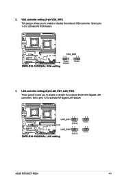
Set to pins 1-2 to activate the VGA feature. 3. VGA controller setting (3-pin VGA_SW1) This jumper allows you to enable or disable the onboard VGA controller. Set to pins 1-2 to activate the Gigabit LAN feature. ASUS RS720-E7-RS24 4-5 2. LAN controller setting (3-pin LAN_SW1, LAN_SW2) These jumpers allow you to enable or disable the onboard Intel® I210 Gigabit LAN controllers.
Set to pins 1-2 to activate the VGA feature. 3. VGA controller setting (3-pin VGA_SW1) This jumper allows you to enable or disable the onboard VGA controller. Set to pins 1-2 to activate the Gigabit LAN feature. ASUS RS720-E7-RS24 4-5 2. LAN controller setting (3-pin LAN_SW1, LAN_SW2) These jumpers allow you to enable or disable the onboard Intel® I210 Gigabit LAN controllers.


