RS720-E7-RS24-EG User's Manual
Page 11
... following parts: 1. Detailed descriptions of the BIOS parameters are also provided. 7 Chapter 7: Driver installation This chapter provides instructions for installing the necessary drivers for system integrators, and experienced users with the server. Chapter 2: Hardware setup This chapter lists the hardware setup procedures that comes with at least basic knowledge of the server, including sections on front panel and rear panel specifications. 2. This chapter includes the motherboard layout, jumper settings, and connector locations. 5. Chapter 6: RAID configuration This...
... following parts: 1. Detailed descriptions of the BIOS parameters are also provided. 7 Chapter 7: Driver installation This chapter provides instructions for installing the necessary drivers for system integrators, and experienced users with the server. Chapter 2: Hardware setup This chapter lists the hardware setup procedures that comes with at least basic knowledge of the server, including sections on front panel and rear panel specifications. 2. This chapter includes the motherboard layout, jumper settings, and connector locations. 5. Chapter 6: RAID configuration This...
RS720-E7-RS24-EG User's Manual
Page 16
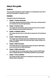
... PCI-E x16 (x16 Gen3 link) 1 x PCI-E x8 (x8 Gen3 link) 1 x PCI-E x16 (x16 Gen3 link) 1 x PCI-E x16 (x16 Gen3 link) 1 x PIKE Slot for Storage expansion 2 x Intel® I210AT controller + 1 Management LAN 1 x Dual port Broadcom 57840S 10GbE controller Intel® C602-A: 4 SATA 3Gb/s ports; 2 SATA 6Gb/s ports Intel® RSTe (for Windows only) (Support software RAID 0, 1, 10, and 5) LSI® MegaRAID driver (Support software RAID 0, 1, and10) (Linux/Windows) ASUS PIKE 2108-32PD 8-port SAS 6G HW RAID card ASUS PIKE 2208 8-port SAS 6G HW RAID card ASUS PIKE 2308 8-port SAS 6G RAID card Default...
... PCI-E x16 (x16 Gen3 link) 1 x PCI-E x8 (x8 Gen3 link) 1 x PCI-E x16 (x16 Gen3 link) 1 x PCI-E x16 (x16 Gen3 link) 1 x PIKE Slot for Storage expansion 2 x Intel® I210AT controller + 1 Management LAN 1 x Dual port Broadcom 57840S 10GbE controller Intel® C602-A: 4 SATA 3Gb/s ports; 2 SATA 6Gb/s ports Intel® RSTe (for Windows only) (Support software RAID 0, 1, 10, and 5) LSI® MegaRAID driver (Support software RAID 0, 1, and10) (Linux/Windows) ASUS PIKE 2108-32PD 8-port SAS 6G HW RAID card ASUS PIKE 2208 8-port SAS 6G HW RAID card ASUS PIKE 2308 8-port SAS 6G RAID card Default...
RS720-E7-RS24-EG User's Manual
Page 17
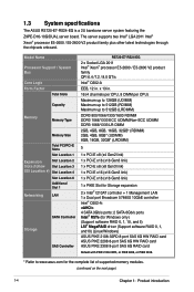
... USB Connectors Onboard I/O Connectors Rear I/O Connectors Fan Header SMBus Chassis Intruder Front LAN LED Serial Port Header SFP+ VGA Port External USB Port RJ-45 PS/2 Keyboard PS/2 Mouse Software Management Out of Band Solution Remote Management Dimension (HH x WW x DD) Net Weight Kg (CPU, DRAM, and HDD not inclu ded) Power Supply RS720-E7-RS24-EG 24 x Hot-swap 2.5-inch HDD bays 2 x Hot-swap 2.5-inch HDD bays (Rear) Aspeed AST2300 16MB 1 1 x USB connector (Type A USB socket) 2 x USB pin header (up to change without notice. Operation temperature...
... USB Connectors Onboard I/O Connectors Rear I/O Connectors Fan Header SMBus Chassis Intruder Front LAN LED Serial Port Header SFP+ VGA Port External USB Port RJ-45 PS/2 Keyboard PS/2 Mouse Software Management Out of Band Solution Remote Management Dimension (HH x WW x DD) Net Weight Kg (CPU, DRAM, and HDD not inclu ded) Power Supply RS720-E7-RS24-EG 24 x Hot-swap 2.5-inch HDD bays 2 x Hot-swap 2.5-inch HDD bays (Rear) Aspeed AST2300 16MB 1 1 x USB connector (Type A USB socket) 2 x USB pin header (up to change without notice. Operation temperature...

RS720-E7-RS24-EG User's Manual
Page 19
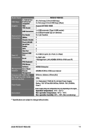
... the power supply before removing or replacing any of the USB ports on the front or rear panel if you need to use a floppy disk. *WARNING HAZARDOUS MOVING PARTS KEEP FINGERS AND OTHER BODY PARTS AWAY ASUS RS720-E7-RS24-EG 1-7 Connect a USB floppy disk drive to any system component. 1.6 Internal features The barebone server includes the basic components as shown. 1. The barebone server does not include a floppy disk drive drive. Redundant Power supply 7 2. Z9PE-D16-10G/DUAL Server Boards 3. SATA backplane (hidden) 5. Front I/O boards...
... the power supply before removing or replacing any of the USB ports on the front or rear panel if you need to use a floppy disk. *WARNING HAZARDOUS MOVING PARTS KEEP FINGERS AND OTHER BODY PARTS AWAY ASUS RS720-E7-RS24-EG 1-7 Connect a USB floppy disk drive to any system component. 1.6 Internal features The barebone server includes the basic components as shown. 1. The barebone server does not include a floppy disk drive drive. Redundant Power supply 7 2. Z9PE-D16-10G/DUAL Server Boards 3. SATA backplane (hidden) 5. Front I/O boards...
RS720-E7-RS24-EG User's Manual
Page 32
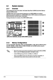
... developed for details. • Install a DIMM beginning with either slot DIMM_A1 or DIMM_E1. • Always install DIMMs with ECC/ Non-ECC UDIMMs or 8GB, 16GB and 32GB LR-DIMMs into the DIMM sockets using the memory configurations in this section. • Remove the chassis cover and the air duct first if you obtain memory modules from the same vendor. 2-10 Chapter 2: Hardware setup For optimum compatibility, it...
... developed for details. • Install a DIMM beginning with either slot DIMM_A1 or DIMM_E1. • Always install DIMMs with ECC/ Non-ECC UDIMMs or 8GB, 16GB and 32GB LR-DIMMs into the DIMM sockets using the memory configurations in this section. • Remove the chassis cover and the air duct first if you obtain memory modules from the same vendor. 2-10 Chapter 2: Hardware setup For optimum compatibility, it...
RS720-E7-RS24-EG User's Manual
Page 37
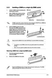
... DIMM notch damage. • To install two or more DIMMs, refer to the user guide bundled in the wrong direction to the user guide for qualified vendor lists of its ends, then insert the DIMM vertically into a socket in the motherboard package. • Refer to avoid damaging the DIMM. 3. ASUS RS720-E7-RS24 Series 2-15 DO NOT force a DIMM into the socket. Removing a DIMM from the socket. 2 1 Support the DIMM lightly...
... DIMM notch damage. • To install two or more DIMMs, refer to the user guide bundled in the wrong direction to the user guide for qualified vendor lists of its ends, then insert the DIMM vertically into a socket in the motherboard package. • Refer to avoid damaging the DIMM. 3. ASUS RS720-E7-RS24 Series 2-15 DO NOT force a DIMM into the socket. Removing a DIMM from the socket. 2 1 Support the DIMM lightly...
RS720-E7-RS24-EG User's Manual
Page 43
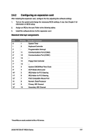
... Port (COM2) 4* 12 Communications Port (COM1) 5* 13 -- 6 14 Floppy Disk Controller 7* 15 -- 8 3 System CMOS/Real Time Clock 9* 4 ACPI Mode when used 10* 5 IRQ Holder for PCI Steering 11* 6 IRQ Holder for PCI Steering 12* 7 PS/2 Compatible Mouse Port 13 8 Numeric Data Processor 14* 9 Primary IDE Channel 15* 10 Secondary IDE Channel * These IRQs are usually available for the expansion card. Install the software drivers for ISA or PCI devices. ASUS RS720-E7-RS24...
... Port (COM2) 4* 12 Communications Port (COM1) 5* 13 -- 6 14 Floppy Disk Controller 7* 15 -- 8 3 System CMOS/Real Time Clock 9* 4 ACPI Mode when used 10* 5 IRQ Holder for PCI Steering 11* 6 IRQ Holder for PCI Steering 12* 7 PS/2 Compatible Mouse Port 13 8 Numeric Data Processor 14* 9 Primary IDE Channel 15* 10 Secondary IDE Channel * These IRQs are usually available for the expansion card. Install the software drivers for ISA or PCI devices. ASUS RS720-E7-RS24...
RS720-E7-RS24-EG User's Manual
Page 65
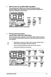
...module cables to the fan connectors. CPU, front, and rear fan connectors (4-pin CPU_FAN1-2, FRNT_FAN1-5, REAR_FAN1-2) The fan connectors support cooling fans. Insufficient air flow inside the system may damage the motherboard components. • These are for USB 2.0 ports. DO NOT place jumper caps on the motherboard, ensuring that supports up to the fan connectors on the fan connectors! • All fans feature the ASUS Smart Fan technology. ASUS RS720-E7-RS24 4-11 3. Connect the fan cables to 480 Mbps connection speed. 4. These USB connectors comply with USB 2.0 specification...
...module cables to the fan connectors. CPU, front, and rear fan connectors (4-pin CPU_FAN1-2, FRNT_FAN1-5, REAR_FAN1-2) The fan connectors support cooling fans. Insufficient air flow inside the system may damage the motherboard components. • These are for USB 2.0 ports. DO NOT place jumper caps on the motherboard, ensuring that supports up to the fan connectors on the fan connectors! • All fans feature the ASUS Smart Fan technology. ASUS RS720-E7-RS24 4-11 3. Connect the fan cables to 480 Mbps connection speed. 4. These USB connectors comply with USB 2.0 specification...
RS720-E7-RS24-EG User's Manual
Page 104
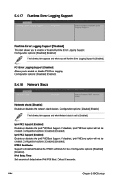
...) and Hour/Minute/ Second will reboot after an AC power loss. Power On By RTC [Disabled] [Disabled] Disables RTC to generate a wake event. [Enabled] When set to generate a wake event. Configuration options: [Power Off] [Power On] [Last State] Power On By PCIE [Disabled] [Disabled] Disables the PCIE devices to generate a wake event. [Enabled] Enables the PCIE devices to [Power On], the system will become user-configurable with set to enable or disable the Windows Hardware Error Architecture support. When set to [Last State], the system goes...
...) and Hour/Minute/ Second will reboot after an AC power loss. Power On By RTC [Disabled] [Disabled] Disables RTC to generate a wake event. [Enabled] When set to generate a wake event. Configuration options: [Power Off] [Power On] [Last State] Power On By PCIE [Disabled] [Disabled] Disables the PCIE devices to generate a wake event. [Enabled] Enables the PCIE devices to [Power On], the system will become user-configurable with set to enable or disable the Windows Hardware Error Architecture support. When set to [Last State], the system goes...
RS720-E7-RS24-EG User's Manual
Page 110
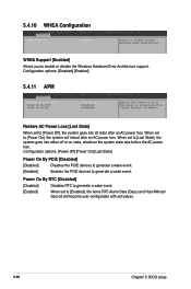
... Support. Ipv4 PXE Support [Enabled] Enables or disables the Ipv4 PXE Boot Support. IPv6 Delay Time: Set seconds of delay before IPv6 PXE Boot. If disabled, Ipv4 PXE boot option will not be created. Ipv6 PXE Support [Enabled] Enables or disables the Ipv6 PXE Boot Support. If disabled, Ipv6 PXE boot option will not be created. Configuration options: [Disabled] [Enabled]. 5.4.17 Runtime Error Logging Support Runtime Error Logging Support [Disabled] This item allows you to Enables/Disables the IPSEC certificate for Ikev. Default 0 seconds. 5-34 Chapter 5: BIOS setup...
... Support. Ipv4 PXE Support [Enabled] Enables or disables the Ipv4 PXE Boot Support. IPv6 Delay Time: Set seconds of delay before IPv6 PXE Boot. If disabled, Ipv4 PXE boot option will not be created. Ipv6 PXE Support [Enabled] Enables or disables the Ipv6 PXE Boot Support. If disabled, Ipv6 PXE boot option will not be created. Configuration options: [Disabled] [Enabled]. 5.4.17 Runtime Error Logging Support Runtime Error Logging Support [Disabled] This item allows you to Enables/Disables the IPSEC certificate for Ikev. Default 0 seconds. 5-34 Chapter 5: BIOS setup...
RS720-E7-RS24-EG User's Manual
Page 121
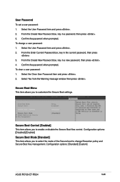
... Secure Boot Key management. From the Create New Password box, key in a password, then press . 3. Confirm the password when prompted. Select Yes from the Warning message window then press . To clear a user password: 1. Configuration options: [Standard] [Custom] ASUS RS720-E7-RS24 5-45 Confirm the password when prompted. From the Enter Current Password box, key in the current password, then press . 3. Select the Clear User Password item and press . 2. Secure Boot Menu This item allows you to enable or disable...
... Secure Boot Key management. From the Create New Password box, key in a password, then press . 3. Confirm the password when prompted. Select Yes from the Warning message window then press . To clear a user password: 1. Configuration options: [Standard] [Custom] ASUS RS720-E7-RS24 5-45 Confirm the password when prompted. From the Enter Current Password box, key in the current password, then press . 3. Select the Clear User Password item and press . 2. Secure Boot Menu This item allows you to enable or disable...
RS720-E7-RS24-EG User's Manual
Page 126
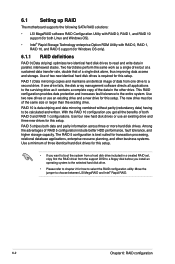
... RAID 5 configuration is required for this setup. • If you want to boot the system from a hard disk drive included in a created RAID set, copy first the RAID driver from one drive fails, the disk array management software directs all the benefits of RAID 5 configuration include better HDD performance, fault tolerance, and higher storage capacity. Two hard disks perform the same work as it contains a complete copy of the data in the other business systems. Use...
... RAID 5 configuration is required for this setup. • If you want to boot the system from a hard disk drive included in a created RAID set, copy first the RAID driver from one drive fails, the disk array management software directs all the benefits of RAID 5 configuration include better HDD performance, fault tolerance, and higher storage capacity. Two hard disks perform the same work as it contains a complete copy of the data in the other business systems. Use...
RS720-E7-RS24-EG User's Manual
Page 127
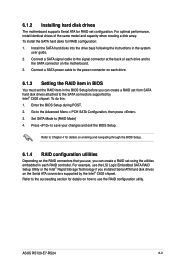
... user guide. 2. ASUS RS720-E7-RS24 6-3 Connect a SATA signal cable to the power connector on how to save your changes and exit the BIOS Setup. To install the SATA hard disks for details on entering and navigating through the BIOS Setup. 6.1.4 RAID configuration utilities Depending on the RAID connectors that you use the LSI Logic Embedded SATA RAID Setup Utility or the Intel® Rapid Storage Technology if you can create a RAID set configuration. Enter the BIOS Setup during POST. 2. For example, use , you installed Serial ATA hard disk drives on the motherboard...
... user guide. 2. ASUS RS720-E7-RS24 6-3 Connect a SATA signal cable to the power connector on how to save your changes and exit the BIOS Setup. To install the SATA hard disks for details on entering and navigating through the BIOS Setup. 6.1.4 RAID configuration utilities Depending on the RAID connectors that you use the LSI Logic Embedded SATA RAID Setup Utility or the Intel® Rapid Storage Technology if you can create a RAID set configuration. Enter the BIOS Setup during POST. 2. For example, use , you installed Serial ATA hard disk drives on the motherboard...
RS720-E7-RS24-EG User's Manual
Page 128
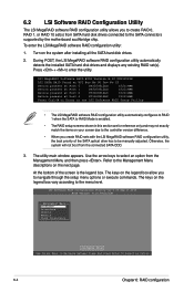
... the Management Menu descriptions on the system after installing all the SATA hard disk drives. 2. The utility main window appears. At the bottom of the SATA optical drive has to Navigate Between Items And Press Enter To Select An Option 6-4 Chapter 6: RAID configuration Turn on the next page. LSI Software RAID Configuration Utility Ver C.05 Sep 17,2010 BIOS Version A.10.09231523R Management Menu Configure Initialize Objects Rebuild Check Consistency Configure VD(s) Use Cursor Keys to be manually...
... the Management Menu descriptions on the system after installing all the SATA hard disk drives. 2. The utility main window appears. At the bottom of the SATA optical drive has to Navigate Between Items And Press Enter To Select An Option 6-4 Chapter 6: RAID configuration Turn on the next page. LSI Software RAID Configuration Utility Ver C.05 Sep 17,2010 BIOS Version A.10.09231523R Management Menu Configure Initialize Objects Rebuild Check Consistency Configure VD(s) Use Cursor Keys to be manually...
RS720-E7-RS24-EG User's Manual
Page 130
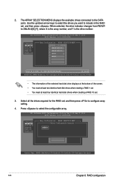
... X is the array number, and Y is the drive number. LSI Software RAID Configuration Utility Ver C.05 Sep 17,2010 BIOS Version A.10.09231523R Easy Configuration - When selected, the drive indicator changes from READY to select the configurable array. Use the up/down arrow keys to select the drives you want to include in the RAID set . 3. Select all the drives required for the RAID set, and then press to the SATA ports. ARRAY SELECTION MENU Management Menu Configure SelectPOCRoTnf#igurable Array(s) Initialize...
... X is the array number, and Y is the drive number. LSI Software RAID Configuration Utility Ver C.05 Sep 17,2010 BIOS Version A.10.09231523R Easy Configuration - When selected, the drive indicator changes from READY to select the configurable array. Use the up/down arrow keys to select the drives you want to include in the RAID set . 3. Select all the drives required for the RAID set, and then press to the SATA ports. ARRAY SELECTION MENU Management Menu Configure SelectPOCRoTnf#igurable Array(s) Initialize...
RS720-E7-RS24-EG User's Manual
Page 135
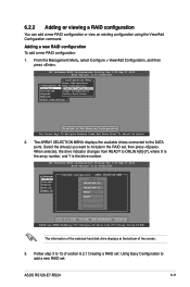
...-Virtual Drives,F4-HSP The information of the selected hard disk drive displays at the bottom of section 6.2.1 Creating a RAID set: Using Easy Configuration to include in the RAID set . The ARRAY SELECTION MENU displays the available drives connected to 12 of the screen. 3. Select the drive(s) you want to add a new RAID set , then press . LSI Software RAID Configuration Utility Ver C.05 Sep 17,2010 BIOS Version A.10.09231523R View/Add Configuration - ASUS RS720-E7-RS24 6-11 Follow step 3 to the SATA ports. From the Management Menu...
...-Virtual Drives,F4-HSP The information of the selected hard disk drive displays at the bottom of section 6.2.1 Creating a RAID set: Using Easy Configuration to include in the RAID set . The ARRAY SELECTION MENU displays the available drives connected to 12 of the screen. 3. Select the drive(s) you want to add a new RAID set , then press . LSI Software RAID Configuration Utility Ver C.05 Sep 17,2010 BIOS Version A.10.09231523R View/Add Configuration - ASUS RS720-E7-RS24 6-11 Follow step 3 to the SATA ports. From the Management Menu...
RS720-E7-RS24-EG User's Manual
Page 138
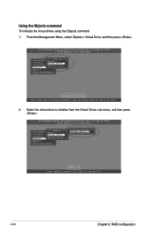
... Drive Objects Rebuild Check Consistency Change VD Parameters Use Cursor Keys To Navigate Between Items And Press Enter To Select An Option 2. Using the Objects command To initialize the virtual drives using the Objects command 1. Select the virtual drive to initialize from the Virtual Drives sub‑menu, and then press . LSI Software RAID Configuration Utility Ver C.05 Sep 17,2010 BIOS Version A.10.09231523R Objects Management MAednaupter Configure Virtual Drive Initialize Physical Drive Objects Rebuild Check Consistency Virtual Drive(1) Virtual Drive...
... Drive Objects Rebuild Check Consistency Change VD Parameters Use Cursor Keys To Navigate Between Items And Press Enter To Select An Option 2. Using the Objects command To initialize the virtual drives using the Objects command 1. Select the virtual drive to initialize from the Virtual Drives sub‑menu, and then press . LSI Software RAID Configuration Utility Ver C.05 Sep 17,2010 BIOS Version A.10.09231523R Objects Management MAednaupter Configure Virtual Drive Initialize Physical Drive Objects Rebuild Check Consistency Virtual Drive(1) Virtual Drive...
RS720-E7-RS24-EG User's Manual
Page 148
...-RAID Disk Non-RAID Disk Non-RAID Disk Non-RAID Disk [ ]-Select [ESC]-Exit [ENTER]-Select Menu The navigation keys at the bottom of the motherboard, and have set the correct SATA mode in this section are connected to the Serial ATA connectors supported by the Southbridge. Create RAID Volume 2. The RAID BIOS setup screens shown in the BIOS setup. During POST, press + to display the utility main menu. Exit RAID Volumes: None defined. You can refer to sections 6.1.2 Installing hard disk drives, 6.1.3 Setting Jumpers...
...-RAID Disk Non-RAID Disk Non-RAID Disk Non-RAID Disk [ ]-Select [ESC]-Exit [ENTER]-Select Menu The navigation keys at the bottom of the motherboard, and have set the correct SATA mode in this section are connected to the Serial ATA connectors supported by the Southbridge. Create RAID Volume 2. The RAID BIOS setup screens shown in the BIOS setup. During POST, press + to display the utility main menu. Exit RAID Volumes: None defined. You can refer to sections 6.1.2 Installing hard disk drives, 6.1.3 Setting Jumpers...
RS720-E7-RS24-EG User's Manual
Page 164
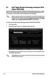
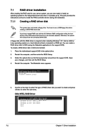
... drive. To create a RAID driver disk in a RAID set. 7.1 RAID driver installation After creating the RAID sets for your changes, and then exit the BIOS Setup. 4. The Makedisk menu appears. A floppy disk with the LSI Software RAID configuration utility, the boot priority of RAID driver disk you want to create and press to be manually adjusted. Otherwise, the system will not boot from the support DVD. Create Driver Diskette Menu C60x INTEL RAID Driver Write DMI FreeDOS command prompt 5. This part provides the instructions on a hard disk drive...
... drive. To create a RAID driver disk in a RAID set. 7.1 RAID driver installation After creating the RAID sets for your changes, and then exit the BIOS Setup. 4. The Makedisk menu appears. A floppy disk with the LSI Software RAID configuration utility, the boot priority of RAID driver disk you want to create and press to be manually adjusted. Otherwise, the system will not boot from the support DVD. Create Driver Diskette Menu C60x INTEL RAID Driver Write DMI FreeDOS command prompt 5. This part provides the instructions on a hard disk drive...
RS720-E7-RS24-EG User's Manual
Page 167
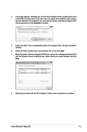
... optical drive installed in the corresponding folder of the RAID controller driver. ASUS RS720-E7-RS24-EG 7-5 4. A message appears, reminding you need from the list and click Next. 7. Select the RAID controller driver you to insert the installation media containing the driver of the Support DVD, and then click OK to continue. Click Browse to install Windows and click Next. 8. When the system finishes loading the RAID driver, replace the motherboard Support DVD with the OS installation. Locate the driver...
... optical drive installed in the corresponding folder of the RAID controller driver. ASUS RS720-E7-RS24-EG 7-5 4. A message appears, reminding you need from the list and click Next. 7. Select the RAID controller driver you to insert the installation media containing the driver of the Support DVD, and then click OK to continue. Click Browse to install Windows and click Next. 8. When the system finishes loading the RAID driver, replace the motherboard Support DVD with the OS installation. Locate the driver...


