RS160-E3
Page 5
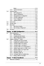
... 5.8 Exit menu 5-41 Chapter 6: RAID Configuration 6-1 6.1 RAID configurations 6-2 6.1.1 RAID definitions 6-2 6.1.2 Installing hard disk drivers 6-3 6.1.3 RAID Configuration utilities 6-3 6.2 Adaptec SCSISelect(TM) Utility 6-4 6.2.1 Configuring the SCSI controller 6-5 6.2.2 Enabling the HostRAID controller 6-5 6.2.3 Creating a RAID 0 set (Stripe 6-6 6.2.4 Creating a RAID 1 set (Mirror 6-10 6.2.5 Creating a RAID 10 set (Stripe+Mirror 6-13 6.2.6 Adding a spare driver to a RAID 10 set...
... 5.8 Exit menu 5-41 Chapter 6: RAID Configuration 6-1 6.1 RAID configurations 6-2 6.1.1 RAID definitions 6-2 6.1.2 Installing hard disk drivers 6-3 6.1.3 RAID Configuration utilities 6-3 6.2 Adaptec SCSISelect(TM) Utility 6-4 6.2.1 Configuring the SCSI controller 6-5 6.2.2 Enabling the HostRAID controller 6-5 6.2.3 Creating a RAID 0 set (Stripe 6-6 6.2.4 Creating a RAID 1 set (Mirror 6-10 6.2.5 Creating a RAID 10 set (Stripe+Mirror 6-13 6.2.6 Adding a spare driver to a RAID 10 set...

RS160-E3
Page 13
...-Channel RAID (optional) Expansion slots 1 x full-length 64-bit/133MHz 3V PCI-X slots (on the next page) ASUS RS160-E3/PS4 1-3 Chassis Rackmount 1U (AR11) Motherboard ASUS PVL-D/1U/SCSI Chipset North Bridge: Intel® E7520 Memory Controller Hub (MCH) South Bridge: Intel® ICH5R I/O Bridge: Intel® PXH CPU Dual 604-pin sockets Intel®...
...-Channel RAID (optional) Expansion slots 1 x full-length 64-bit/133MHz 3V PCI-X slots (on the next page) ASUS RS160-E3/PS4 1-3 Chassis Rackmount 1U (AR11) Motherboard ASUS PVL-D/1U/SCSI Chipset North Bridge: Intel® E7520 Memory Controller Hub (MCH) South Bridge: Intel® ICH5R I/O Bridge: Intel® PXH CPU Dual 604-pin sockets Intel®...
RS160-E3
Page 31
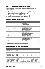
... - - See Chapter 5 for this motherboard ICH5R IDE contrl. PIRQC# - - - - - REQ1H# GNT1# PXH1_B_0 PXH1_B_1 PXH1_B_2 PXH1_B_3 PXH1_B_0 PXH1_B_0 ASUS RS160-E3/PS4 2-13 Turn on BIOS setup. 2. PXH2_A_0 PXH2_A_1 - - Install the software drivers for ISA or PCI devices. PXH2_A_0 PXH2_A_0 PXH2_A_2 - - - ... 6 12* 7 13 8 14* 9 15* 10 System Timer Keyboard Controller Re-direct to IRQ9# Communications Port (COM2) Communications Port (COM1) IRQ Holder for PCI steering Floppy Disk Controller Printer Port (LPT1) System CMOS/Real Time Clock IRQ Holder for PCI Steering...
... - - See Chapter 5 for this motherboard ICH5R IDE contrl. PIRQC# - - - - - REQ1H# GNT1# PXH1_B_0 PXH1_B_1 PXH1_B_2 PXH1_B_3 PXH1_B_0 PXH1_B_0 ASUS RS160-E3/PS4 2-13 Turn on BIOS setup. 2. PXH2_A_0 PXH2_A_1 - - Install the software drivers for ISA or PCI devices. PXH2_A_0 PXH2_A_0 PXH2_A_2 - - - ... 6 12* 7 13 8 14* 9 15* 10 System Timer Keyboard Controller Re-direct to IRQ9# Communications Port (COM2) Communications Port (COM1) IRQ Holder for PCI steering Floppy Disk Controller Printer Port (LPT1) System CMOS/Real Time Clock IRQ Holder for PCI Steering...

RS160-E3
Page 33
2-15 ASUS RS160-E3/PS4 USB 2.0 cable to front panel board 20-pin front panel cable to front panel board IDE cable to optical drive 30.5cm (12in) SCSI cable ..., 133MHz 3V) VGA_EN1 CPU2 J2 Intel® PXH CPU_FAN2 FM_CPU2 SEC_IDE PRI_IDE Intel® ICH5R mPGA 604 SATA2 SATA1 FRNT_FAN1 FRNT_FAN2 ATI RAGE XL VGA Controller SB_PWR1 COM2 BMC_RACK1 BPSMB1 FLOPPY1 BMCCONN1 CR2032 3V Lithium Cell CMOS Power BUZZ1 CLRTC1 AUX_PANEL1 USB34 Intel® PXH HDLED1 SCSI_EN1 PANEL1 Adaptec® AIC...
2-15 ASUS RS160-E3/PS4 USB 2.0 cable to front panel board 20-pin front panel cable to front panel board IDE cable to optical drive 30.5cm (12in) SCSI cable ..., 133MHz 3V) VGA_EN1 CPU2 J2 Intel® PXH CPU_FAN2 FM_CPU2 SEC_IDE PRI_IDE Intel® ICH5R mPGA 604 SATA2 SATA1 FRNT_FAN1 FRNT_FAN2 ATI RAGE XL VGA Controller SB_PWR1 COM2 BMC_RACK1 BPSMB1 FLOPPY1 BMCCONN1 CR2032 3V Lithium Cell CMOS Power BUZZ1 CLRTC1 AUX_PANEL1 USB34 Intel® PXH HDLED1 SCSI_EN1 PANEL1 Adaptec® AIC...

RS160-E3
Page 34
Cable from device fan 8-pin plug from power supply SCSI connector for hot-swap HDD4 Cable from system fan Cable from system fan SCSI connector for hot-swap HDD3 Cable from system fan Cable from system fan SCSI cable from MB SCSIA1 connector 2-16 Cable from device fan fan-control SCSI connector for hot-swap HDD2 SCSI connector for hot-swap HDD1 Cable from SMBus Chapter 2: Hardware setup 2.6.2 SCSI backplane The following illustration describes the cables/devices that are connected to the SCSI backplane board.
Cable from device fan 8-pin plug from power supply SCSI connector for hot-swap HDD4 Cable from system fan Cable from system fan SCSI connector for hot-swap HDD3 Cable from system fan Cable from system fan SCSI cable from MB SCSIA1 connector 2-16 Cable from device fan fan-control SCSI connector for hot-swap HDD2 SCSI connector for hot-swap HDD1 Cable from SMBus Chapter 2: Hardware setup 2.6.2 SCSI backplane The following illustration describes the cables/devices that are connected to the SCSI backplane board.

RS160-E3
Page 47
... panel connector (20-pin AUX_PANEL1) Page 4-9 4-9 4-10 4-11 4-12 4-12 4-13 4-13 4-14 4-14 4-14 4-15 4-16 4-17 ASUS RS160-E3/PS4 4-3 Zero-Channel RAID socket 5. USB device wake-up (3-pin USBPW12, USBPW34) 4. Floppy disk drive connector (34-1 pin FLOPPY1) 2. IDE connectors ...(24-pin ATXPWR1, 8-pin ATX12V1) 13. CPU fan pin selection (3-pin FM_CPU1, FM_CPU2) 3. Keyboard power (3-pin KBPWR1) 5. Gigabit LAN controller setting (3-pin LAN1_EN1) 7. CPU and system fan connectors (3-pin CPU_FAN1/2, REAR_FAN1/2, FRNT_FAN1/2) 9. USB connector (10-1 pin USB34) 7. Serial port...
... panel connector (20-pin AUX_PANEL1) Page 4-9 4-9 4-10 4-11 4-12 4-12 4-13 4-13 4-14 4-14 4-14 4-15 4-16 4-17 ASUS RS160-E3/PS4 4-3 Zero-Channel RAID socket 5. USB device wake-up (3-pin USBPW12, USBPW34) 4. Floppy disk drive connector (34-1 pin FLOPPY1) 2. IDE connectors ...(24-pin ATXPWR1, 8-pin ATX12V1) 13. CPU fan pin selection (3-pin FM_CPU1, FM_CPU2) 3. Keyboard power (3-pin KBPWR1) 5. Gigabit LAN controller setting (3-pin LAN1_EN1) 7. CPU and system fan connectors (3-pin CPU_FAN1/2, REAR_FAN1/2, FRNT_FAN1/2) 9. USB connector (10-1 pin USB34) 7. Serial port...

RS160-E3
Page 50
... to pins 2-3 (+5VSB) to activate the VGA feature. PVL-D/1U/SCSI ® PVL-D/1U/SCSI VGA setting VGA_EN1 1 2 Enable (Default) 2 3 Disable 4-6 Chapter 4: Motherboard information VGA controller setting (3-pin VGA_EN1) These jumpers allow you to enable or disable the onboard ATI® RAGE-XL PCI VGA... controller. Keyboard power (3-pin KBPWR1) This jumper allows you to enable or disable the keyboard wake-up the computer when you press a key on the +5VSB ...
... to pins 2-3 (+5VSB) to activate the VGA feature. PVL-D/1U/SCSI ® PVL-D/1U/SCSI VGA setting VGA_EN1 1 2 Enable (Default) 2 3 Disable 4-6 Chapter 4: Motherboard information VGA controller setting (3-pin VGA_EN1) These jumpers allow you to enable or disable the onboard ATI® RAGE-XL PCI VGA... controller. Keyboard power (3-pin KBPWR1) This jumper allows you to enable or disable the keyboard wake-up the computer when you press a key on the +5VSB ...

RS160-E3
Page 51
...) This jumper allows you to enable or disable the onboard Broadcom® BCM5721 Gigabit LAN1 controller. Set to pins 1-2 to activate the Gigabit LAN feature. PVL-D/1U/SCSI ® LAN1_EN1 2 1 Enable (Default) PVL-D/1U/SCSI LAN1_EN setting 3 2 Disable 7. PVL-D/1U/SCSI ® LAN2_EN1 2 1 Enable (Default) PVL-D/1U/SCSI LAN2_EN setting 3 2 Disable ASUS RS160-E3/PS4 4-7
...) This jumper allows you to enable or disable the onboard Broadcom® BCM5721 Gigabit LAN1 controller. Set to pins 1-2 to activate the Gigabit LAN feature. PVL-D/1U/SCSI ® LAN1_EN1 2 1 Enable (Default) PVL-D/1U/SCSI LAN1_EN setting 3 2 Disable 7. PVL-D/1U/SCSI ® LAN2_EN1 2 1 Enable (Default) PVL-D/1U/SCSI LAN2_EN setting 3 2 Disable ASUS RS160-E3/PS4 4-7

RS160-E3
Page 52
... the AFUDOS.EXE utility. 2. Set the jumper back to pins 2-3. 3. Set to pins 1-2 to enable or disable the onboard Adaptec® AIC-7902W SCSI U320 controller. 8. SCSI controller setting (3-pin SCSI_EN1) This jumper allows you to update the BIOS. 4.
... the AFUDOS.EXE utility. 2. Set the jumper back to pins 2-3. 3. Set to pins 1-2 to enable or disable the onboard Adaptec® AIC-7902W SCSI U320 controller. 8. SCSI controller setting (3-pin SCSI_EN1) This jumper allows you to update the BIOS. 4.

RS160-E3
Page 54
... hard disk drives, you can create a RAID 0 or RAID 1 configuration with the Adaptec® HostRAID™ Technology through the onboard Intel® ICH5R integrated RAID controller.
... hard disk drives, you can create a RAID 0 or RAID 1 configuration with the Adaptec® HostRAID™ Technology through the onboard Intel® ICH5R integrated RAID controller.

RS160-E3
Page 55
...-D/SCSI SCSI connection example 68-pin Female Terminator ASUS RS160-E3/PS4 4-11 Mixing SCSI devices on the same channel decreases performance of 15 devices as shown. Ultra320 SCSI connectors (two 68-pin SCSIA1, SCSIB1) This motherboard comes with the Adaptec® AIC-7902W SCSI U320 controller that supports both single-ended (SE), Ultra2, Ultra160...
...-D/SCSI SCSI connection example 68-pin Female Terminator ASUS RS160-E3/PS4 4-11 Mixing SCSI devices on the same channel decreases performance of 15 devices as shown. Ultra320 SCSI connectors (two 68-pin SCSIA1, SCSIB1) This motherboard comes with the Adaptec® AIC-7902W SCSI U320 controller that supports both single-ended (SE), Ultra2, Ultra160...

RS160-E3
Page 57
... ® GND FAN Power FAN Speed PWM Control PWM Control FAN Speed FAN Power GND CPU_FAN1 REAR_FAN2 CPU_FAN1 CPU_FAN2 REAR_FAN1 CPU_FAN2 FRNT_FAN1 FRNT_FAN2 PVL-D/1U/SCSI Fan connectors REAR_FAN1 GND +12V Rotation FRNT_FAN1 GND +12V Rotation REAR_FAN2 Rotation +12V GND FRNT_FAN2 GND +12V Rotation ASUS RS160-E3/PS4 4-13 Connect the serial port module cable to...
... ® GND FAN Power FAN Speed PWM Control PWM Control FAN Speed FAN Power GND CPU_FAN1 REAR_FAN2 CPU_FAN1 CPU_FAN2 REAR_FAN1 CPU_FAN2 FRNT_FAN1 FRNT_FAN2 PVL-D/1U/SCSI Fan connectors REAR_FAN1 GND +12V Rotation FRNT_FAN1 GND +12V Rotation REAR_FAN2 Rotation +12V GND FRNT_FAN2 GND +12V Rotation ASUS RS160-E3/PS4 4-13 Connect the serial port module cable to...

RS160-E3
Page 81
...menu The Advanced menu items allow you to select the multi-processor system version. Configuration options: [1.1] [1.4] ASUS RS160-E3/PS4 5-19 Take caution when changing the settings of the Advanced menu items. Incorrect field values can cause the...UTILITY Configure Advanced CPU settings MPS Table Version Single Logical Processor Mode: Hyper Threading Technology Max CPUID Value Limit Execute Disable Function Enhanced C1 Control CPU Internal Thermal Control [1.4] [Disabled] [Enabled] [Disabled] [Disabled] [Auto] [Auto] Intel(R) SpeedStep(tm) Tech. [Automatic] Select MPS Revision. ...
...menu The Advanced menu items allow you to select the multi-processor system version. Configuration options: [1.1] [1.4] ASUS RS160-E3/PS4 5-19 Take caution when changing the settings of the Advanced menu items. Incorrect field values can cause the...UTILITY Configure Advanced CPU settings MPS Table Version Single Logical Processor Mode: Hyper Threading Technology Max CPUID Value Limit Execute Disable Function Enhanced C1 Control CPU Internal Thermal Control [1.4] [Disabled] [Enabled] [Disabled] [Disabled] [Auto] [Auto] Intel(R) SpeedStep(tm) Tech. [Automatic] Select MPS Revision. ...

RS160-E3
Page 82
...without support for dualcore CPUs. In C1E mode, the CPU has lower power consumption. Configuration options: [Auto] [Disabled] CPU Internal Thermal Control [Auto] When this item is set to [Auto], BIOS automatically checks the CPU capability to enable C1E support. Configuration options: [Disabled... Intel® Pentium® 4 CPU that supports EIST. 5-20 Chapter 5: BIOS setup Configuration options: [Disabled] [Enabled] Enhanced C1 Control [Auto] When this item is set to [Auto], BIOS automatically checks the CPU capability to enable TM or TM2 support. Single Logical Processor...
...without support for dualcore CPUs. In C1E mode, the CPU has lower power consumption. Configuration options: [Auto] [Disabled] CPU Internal Thermal Control [Auto] When this item is set to [Auto], BIOS automatically checks the CPU capability to enable C1E support. Configuration options: [Disabled... Intel® Pentium® 4 CPU that supports EIST. 5-20 Chapter 5: BIOS setup Configuration options: [Disabled] [Enabled] Enhanced C1 Control [Auto] When this item is set to [Auto], BIOS automatically checks the CPU capability to enable TM or TM2 support. Single Logical Processor...

RS160-E3
Page 83
... below sections may cause system to enable or disable the option ROM in the onboard LAN controller. Northbridge Configuration Onboard LAN Boot ROM Onboard SCSI Boot ROM [Enabled] [Enabled] Options for NB. Configuration options: [Disabled] [Enabled] ASUS RS160-E3/PS4 5-21 Select an item then press to change the advanced chipset settings. Select Screen Select...
... below sections may cause system to enable or disable the option ROM in the onboard LAN controller. Northbridge Configuration Onboard LAN Boot ROM Onboard SCSI Boot ROM [Enabled] [Enabled] Options for NB. Configuration options: [Disabled] [Enabled] ASUS RS160-E3/PS4 5-21 Select an item then press to change the advanced chipset settings. Select Screen Select...
RS160-E3
Page 85
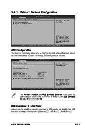
... B D e v i c e s E n a b l e d item shows N o n e. USB Configuration The items in this menu allows you to display the configuration options. Configuration options: [Disabled] [2 USB Ports] [4 USB Ports] ASUS RS160-E3/PS4 5-23 The M o d u l e V e r s i o n and U S B D e v i c e s E n a b l e d items show the auto-detected values. Change Option F1 General Help F10 Save... - 2.23.2-5.3 USB Devices Enabled: None USB Function Legacy USB Support USB 2.0 Controller USB 2.0 Controller Mode [4 USB Ports] [Auto] [Enabled] [HiSpeed] USB Mass Storage Device Configuration Enables USB host...
... B D e v i c e s E n a b l e d item shows N o n e. USB Configuration The items in this menu allows you to display the configuration options. Configuration options: [Disabled] [2 USB Ports] [4 USB Ports] ASUS RS160-E3/PS4 5-23 The M o d u l e V e r s i o n and U S B D e v i c e s E n a b l e d items show the auto-detected values. Change Option F1 General Help F10 Save... - 2.23.2-5.3 USB Devices Enabled: None USB Function Legacy USB Support USB 2.0 Controller USB 2.0 Controller Mode [4 USB Ports] [Auto] [Enabled] [HiSpeed] USB Mass Storage Device Configuration Enables USB host...

RS160-E3
Page 86
...for the USB mass device after start unit command. Setting to [Auto] allows the system to set the USB 2.0 controller mode to enable or disable the USB 2.0 controller. If no legacy USB device is detected, the legacy USB support is enabled. Configuration options: [Enabled] [Disabled] ...F10 Save and Exit ESC Exit v02.58 (C)Copyright 1985-2004, American Megatrends, Inc. Configuration options: [Disabled] [Enabled] [Auto] USB 2.0 Controller [Enabled] Allows you to enable or disable support for the USB mass device after start unit command. Select Screen Select Item +- Legacy USB Support ...
...for the USB mass device after start unit command. Setting to [Auto] allows the system to set the USB 2.0 controller mode to enable or disable the USB 2.0 controller. If no legacy USB device is detected, the legacy USB support is enabled. Configuration options: [Enabled] [Disabled] ...F10 Save and Exit ESC Exit v02.58 (C)Copyright 1985-2004, American Megatrends, Inc. Configuration options: [Disabled] [Enabled] [Auto] USB 2.0 Controller [Enabled] Allows you to enable or disable support for the USB mass device after start unit command. Select Screen Select Item +- Legacy USB Support ...

RS160-E3
Page 90
... set to display the configuration options. Select an item then press to Enabled, the ACPI APIC table pointer is included in the Advanced Programmable Interrupt Controller (APIC). ACPI APIC Support [Enabled] Allows you to change the APIC support settings after OS installation; Advanced Power Configuration ACPI APIC Support APM Configuration BIOS...
... set to display the configuration options. Select an item then press to Enabled, the ACPI APIC table pointer is included in the Advanced Programmable Interrupt Controller (APIC). ACPI APIC Support [Enabled] Allows you to change the APIC support settings after OS installation; Advanced Power Configuration ACPI APIC Support APM Configuration BIOS...

RS160-E3
Page 93
... [N/A] The onboard hardware monitor automatically detects and displays the CPU, front, and rear fan speeds in rotations per minute (RPM). ASUS RS160-E3/PS4 5-31 Use the down arrow key to the connector on the motherboard, the field shows N/A. If a fan is not connected ...e r a t u r e item shows [N/A]. Change Option F1 General Help F10 Save and Exit ESC Exit v02.58 (C)Copyright 1985-2004, American Megatrends, Inc. Smart Fan Control CPU1 Temperature CPU2 Temperature MB Temperature VCORE1 Voltage [Smart Fan II] [060] [060] [50] [ 1.236V] Select Screen Select Item +- If you do not wish to...
... [N/A] The onboard hardware monitor automatically detects and displays the CPU, front, and rear fan speeds in rotations per minute (RPM). ASUS RS160-E3/PS4 5-31 Use the down arrow key to the connector on the motherboard, the field shows N/A. If a fan is not connected ...e r a t u r e item shows [N/A]. Change Option F1 General Help F10 Save and Exit ESC Exit v02.58 (C)Copyright 1985-2004, American Megatrends, Inc. Smart Fan Control CPU1 Temperature CPU2 Temperature MB Temperature VCORE1 Voltage [Smart Fan II] [060] [060] [50] [ 1.236V] Select Screen Select Item +- If you do not wish to...

RS160-E3
Page 94
... Fan II] The C P U 1 T e m p e r a t u r e, C P U 2 T e m p e r a t u r e, and M B T e m p e r a t u r e items do not appear when you to enable or disable the ASUS Q-Fan feature that smartly adjusts the fan speeds for more efficient system operation. VCORE1 Voltage, VCORE2 Voltage, 3.3V Voltage, 5V Voltage, 5VSB Voltage, VBAT Voltage, ...setup CPU1/CPU2 Temperature [XXX] MB Temperature [XXX] Displays the detected CPU and system threshold temperatures when the Smart Fan Control feature is enabled. Smart Fan Control [Smart Fan II] Allows you disable the S m a r t F a n C o n t r o l feature.
... Fan II] The C P U 1 T e m p e r a t u r e, C P U 2 T e m p e r a t u r e, and M B T e m p e r a t u r e items do not appear when you to enable or disable the ASUS Q-Fan feature that smartly adjusts the fan speeds for more efficient system operation. VCORE1 Voltage, VCORE2 Voltage, 3.3V Voltage, 5V Voltage, 5VSB Voltage, VBAT Voltage, ...setup CPU1/CPU2 Temperature [XXX] MB Temperature [XXX] Displays the detected CPU and system threshold temperatures when the Smart Fan Control feature is enabled. Smart Fan Control [Smart Fan II] Allows you disable the S m a r t F a n C o n t r o l feature.