RS160-E3
Page 5
...Configuration 5-23 5.4.4 PCI/PnP Configuration 5-27 5.4.5 Power Configuration 5-28 5.4.6 Hardware Monitor 5-31 5.5 Server menu 5-33 5.6 Security menu 5-35 5.7 Boot menu 5-38 5.7.1 Boot Device Priority 5-38 5.7.2 Boot Settings Configuration 5-39 5.8 Exit menu 5-41 Chapter 6: RAID Configuration 6-1 6.1 RAID configurations 6-2 6.1.1 RAID definitions 6-2 6.1.2 Installing hard disk drivers 6-3 6.1.3 RAID Configuration utilities 6-3 6.2 Adaptec SCSISelect(TM) Utility 6-4 6.2.1 Configuring the SCSI controller 6-5 6.2.2 Enabling the HostRAID controller 6-5 6.2.3 Creating a RAID 0 set...
...Configuration 5-23 5.4.4 PCI/PnP Configuration 5-27 5.4.5 Power Configuration 5-28 5.4.6 Hardware Monitor 5-31 5.5 Server menu 5-33 5.6 Security menu 5-35 5.7 Boot menu 5-38 5.7.1 Boot Device Priority 5-38 5.7.2 Boot Settings Configuration 5-39 5.8 Exit menu 5-41 Chapter 6: RAID Configuration 6-1 6.1 RAID configurations 6-2 6.1.1 RAID definitions 6-2 6.1.2 Installing hard disk drivers 6-3 6.1.3 RAID Configuration utilities 6-3 6.2 Adaptec SCSISelect(TM) Utility 6-4 6.2.1 Configuring the SCSI controller 6-5 6.2.2 Enabling the HostRAID controller 6-5 6.2.3 Creating a RAID 0 set...
RS160-E3
Page 9
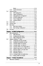
... following parts: 1. Chapter 3: Installation options This chapter describes how to change the system settings through the BIOS Setup menus. About this guide Audience This user guide is intended for system integrators and experienced users with the server. Detailed descriptions of the BIOS parameters are also provided. 7 Chapter 7: Driver installation This chapter provides instructions for installing the necessary drivers for rack mounting. 4. ix This chapter includes the motherboard layout, jumper settings, and connector locations. 5. Chapter 6: RAID configuration...
... following parts: 1. Chapter 3: Installation options This chapter describes how to change the system settings through the BIOS Setup menus. About this guide Audience This user guide is intended for system integrators and experienced users with the server. Detailed descriptions of the BIOS parameters are also provided. 7 Chapter 7: Driver installation This chapter provides instructions for installing the necessary drivers for rack mounting. 4. ix This chapter includes the motherboard layout, jumper settings, and connector locations. 5. Chapter 6: RAID configuration...

RS160-E3
Page 10
... that you perform certain tasks properly, take note of the following sources for additional information, and for all ASUS hardware and software products. W A R N I O N : Information to prevent damage to the components when trying to set up and use the proprietary ASUS server management utility. 3. N O T E : Tips and information to the ASUS contact information. ASUS Server Web-based Management (ASWM) user guide This manual tells how to complete a task.
... that you perform certain tasks properly, take note of the following sources for additional information, and for all ASUS hardware and software products. W A R N I O N : Information to prevent damage to the components when trying to set up and use the proprietary ASUS server management utility. 3. N O T E : Tips and information to the ASUS contact information. ASUS Server Web-based Management (ASWM) user guide This manual tells how to complete a task.

RS160-E3
Page 13
... 64-bit 133MHz 3V PCI-X slots* 1 x mini-PCI socket for ASUS Server Management Board Storage 4 x 3.5-inch hot-swappable SCSI HDD bays 1 x slim optical drive Front panel 2 x USB 2.0 ports Power switch Reset switch Location switch Power, HDD access, location, message, LAN 1, LAN 2 HDD LEDs: Status, activity * When system detlects 2 cards are presented, freguency will be limited to 16GB system memory LAN 2 x Broadcom® BCM5721 PCI Express Gigabit LAN controllers comply with PCI Express 1.0a specifications VGA ATI RAGE-XL PCI-based VGA controller Supports 8MB display memory SCSI...
... 64-bit 133MHz 3V PCI-X slots* 1 x mini-PCI socket for ASUS Server Management Board Storage 4 x 3.5-inch hot-swappable SCSI HDD bays 1 x slim optical drive Front panel 2 x USB 2.0 ports Power switch Reset switch Location switch Power, HDD access, location, message, LAN 1, LAN 2 HDD LEDs: Status, activity * When system detlects 2 cards are presented, freguency will be limited to 16GB system memory LAN 2 x Broadcom® BCM5721 PCI Express Gigabit LAN controllers comply with PCI Express 1.0a specifications VGA ATI RAGE-XL PCI-based VGA controller Supports 8MB display memory SCSI...

RS160-E3
Page 25
... DDR2 memory modules. • This motherboard does not support memory modules made up of the DDR2 DIMM sockets: PVL-D/1U/SCSI ® 128 Pins PVL-D/1U/SCSI 240-pin DDR2 DIMM sockets 112 Pins DIMM_B4 DIMM_A4 DIMM_B3 DIMM_A3 DIMM_B2 DIMM_A2 DIMM_B1 DIMM_A1 2.3.2 Memory configurations You may install 256 MB, 512 MB, 1 GB, and 2 GB registered ECC DDR2 DIMMs into the DIMM sockets. • Always install DIMMs with DIMM ASUS RS160-E3/PS4...
... DDR2 memory modules. • This motherboard does not support memory modules made up of the DDR2 DIMM sockets: PVL-D/1U/SCSI ® 128 Pins PVL-D/1U/SCSI 240-pin DDR2 DIMM sockets 112 Pins DIMM_B4 DIMM_A4 DIMM_B3 DIMM_A3 DIMM_B2 DIMM_A2 DIMM_B1 DIMM_A1 2.3.2 Memory configurations You may install 256 MB, 512 MB, 1 GB, and 2 GB registered ECC DDR2 DIMMs into the DIMM sockets. • Always install DIMMs with DIMM ASUS RS160-E3/PS4...
RS160-E3
Page 31
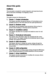
... RAID sockets ATI RAGE XL video contrl. PXH2_A_1 PXH2_A_1 PIRQB# - - - PIRQC# - - - - - Install the software drivers for ISA or PCI devices. 2.5.2 Configuring an expansion card After installing the expansion card, configure the it by adjusting the software settings. 1. IRQ assignments for information on the system and change the necessary BIOS settings, if any. Assign an IRQ to the following tables. 3. Turn on BIOS setup. 2. ICH5R SATA contrl. ICH5R USB UHCI contrl. #1 ICH5R USB UHCI contrl.#2 ICH5R USB...
... RAID sockets ATI RAGE XL video contrl. PXH2_A_1 PXH2_A_1 PIRQB# - - - PIRQC# - - - - - Install the software drivers for ISA or PCI devices. 2.5.2 Configuring an expansion card After installing the expansion card, configure the it by adjusting the software settings. 1. IRQ assignments for information on the system and change the necessary BIOS settings, if any. Assign an IRQ to the following tables. 3. Turn on BIOS setup. 2. ICH5R SATA contrl. ICH5R USB UHCI contrl. #1 ICH5R USB UHCI contrl.#2 ICH5R USB...

RS160-E3
Page 49
... using Windows 2000, you need to install Service Pack 4 to wake up the computer from S4 sleep mode (no power to wake up feature requires a power supply that can provide 500mA on the +5VSB lead for each USB port; USB device wake-up (3-pin USBPW12, USBPW34) Set these jumpers to pins 1-2 if you are using a 4-pin plug. CPU fan pin selection (3-pin FM_CPU1, FM_CPU2) These jumpers allow you to connect...
... using Windows 2000, you need to install Service Pack 4 to wake up the computer from S4 sleep mode (no power to wake up feature requires a power supply that can provide 500mA on the +5VSB lead for each USB port; USB device wake-up (3-pin USBPW12, USBPW34) Set these jumpers to pins 1-2 if you are using a 4-pin plug. CPU fan pin selection (3-pin FM_CPU1, FM_CPU2) These jumpers allow you to connect...

RS160-E3
Page 53
... IDE master device (hard disk drive). Refer to the hard disk documentation for the jumper settings. • Pin 20 on the IDE connector is removed to match the covered hole on the IDE ribbon cable to PIN 1. Insert one end of the cable to this connector, then connect the other end to prevent incorrect cable connection when using a FDD cable with a covered Pin 5. PVL-D/1U/SCSI ® PVL-D/1U/SCSI IDE connectors ASUS RS160-E3/PS4 SEC_IDE PIN...
... IDE master device (hard disk drive). Refer to the hard disk documentation for the jumper settings. • Pin 20 on the IDE connector is removed to match the covered hole on the IDE ribbon cable to PIN 1. Insert one end of the cable to this connector, then connect the other end to prevent incorrect cable connection when using a FDD cable with a covered Pin 5. PVL-D/1U/SCSI ® PVL-D/1U/SCSI IDE connectors ASUS RS160-E3/PS4 SEC_IDE PIN...

RS160-E3
Page 54
...174; ICH5R integrated RAID controller. See section "4.3.5 IDE Configuration" on Serial ATA • You must install Windows® 2000 Service Pack 4 or the Windows® XP Service Pack 1 before using Serial ATA hard disk drives. Serial ATA hard disk drive connection Connector SATA1 SATA2 Setting Master Slave Use Boot disk Data disk 4-10 Chapter 4: Motherboard information In St a n d a r d I D E mode by default. These connectors are using Windows® 2000/XP. • Use only two Serial ATA RAID connectors for the recommended SATA hard disk drive connections. Refer to...
...174; ICH5R integrated RAID controller. See section "4.3.5 IDE Configuration" on Serial ATA • You must install Windows® 2000 Service Pack 4 or the Windows® XP Service Pack 1 before using Serial ATA hard disk drives. Serial ATA hard disk drive connection Connector SATA1 SATA2 Setting Master Slave Use Boot disk Data disk 4-10 Chapter 4: Motherboard information In St a n d a r d I D E mode by default. These connectors are using Windows® 2000/XP. • Use only two Serial ATA RAID connectors for the recommended SATA hard disk drive connections. Refer to...

RS160-E3
Page 78
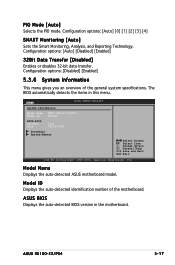
... are not user-configurable. Configuration options: [Not Installed] [Auto] [CDROM] [ARMD] LBA/Large Mode [Auto] Enables or disables the LBA mode. Configuration options: [Disabled] [Auto] 5-16 Chapter 5: BIOS setup The BIOS automatically detects the values opposite the dimmed items (Device, Vendor, Size, LBA Mode, Block Mode, PIO Mode, Async DMA, Ultra DMA, and SMART monitoring). These items show N/A if no IDE device is installed in the system. Main Primary IDE Master BIOS SETUP UTILITY Device : Hard Disk Vendor...
... are not user-configurable. Configuration options: [Not Installed] [Auto] [CDROM] [ARMD] LBA/Large Mode [Auto] Enables or disables the LBA mode. Configuration options: [Disabled] [Auto] 5-16 Chapter 5: BIOS setup The BIOS automatically detects the values opposite the dimmed items (Device, Vendor, Size, LBA Mode, Block Mode, PIO Mode, Async DMA, Ultra DMA, and SMART monitoring). These items show N/A if no IDE device is installed in the system. Main Primary IDE Master BIOS SETUP UTILITY Device : Hard Disk Vendor...
RS160-E3
Page 79
... or disables 32-bit data transfer. Main System Information BIOS SETUP UTILITY Model Name ASUS PVL-D/1U/SCSI Model ID 8021A0 ASUS-BIOS Version Date 1001 09/20/2005 Processor System Memory Select Screen Select Item +- ASUS BIOS Displays the auto-detected BIOS version in this menu. Model Name Displays the auto-detected ASUS motherboard model. Model ID Displays the auto-detected identification number of the general system specifications. Configuration options: [Disabled] [Enabled] 5.3.6 System Information This menu gives you an overview of the motherboard. ASUS RS160-E3/PS4...
... or disables 32-bit data transfer. Main System Information BIOS SETUP UTILITY Model Name ASUS PVL-D/1U/SCSI Model ID 8021A0 ASUS-BIOS Version Date 1001 09/20/2005 Processor System Memory Select Screen Select Item +- ASUS BIOS Displays the auto-detected BIOS version in this menu. Model Name Displays the auto-detected ASUS motherboard model. Model ID Displays the auto-detected identification number of the general system specifications. Configuration options: [Disabled] [Enabled] 5.3.6 System Information This menu gives you an overview of the motherboard. ASUS RS160-E3/PS4...

RS160-E3
Page 81
...this menu show the CPU-related information that the BIOS automatically detects. Configuration options: [1.1] [1.4] ASUS RS160-E3/PS4 5-19 Take caution when changing the settings of the Advanced menu items. Incorrect field values can cause the system to change the settings for the CPU and other system devices. Advanced BIOS SETUP UTILITY Configure Advanced CPU settings MPS Table Version Single Logical Processor Mode: Hyper Threading Technology Max CPUID Value Limit Execute Disable Function Enhanced C1 Control CPU Internal Thermal Control [1.4] [Disabled] [Enabled] [Disabled] [Disabled...
...this menu show the CPU-related information that the BIOS automatically detects. Configuration options: [1.1] [1.4] ASUS RS160-E3/PS4 5-19 Take caution when changing the settings of the Advanced menu items. Incorrect field values can cause the system to change the settings for the CPU and other system devices. Advanced BIOS SETUP UTILITY Configure Advanced CPU settings MPS Table Version Single Logical Processor Mode: Hyper Threading Technology Max CPUID Value Limit Execute Disable Function Enhanced C1 Control CPU Internal Thermal Control [1.4] [Disabled] [Enabled] [Disabled] [Disabled...

RS160-E3
Page 84
... of overlapped PCI memory above the total physical memory. This item is auto-detected and is not configurable. NorthBridge Configuration The NorthBridge Configuration menu allows you to remap the overlap PCI memory over the total physical memory. Memory Remap Feature [Enabled] Allows you to select the memory RAS feature: mirroring or sparing. DIMM Speed Displays the installed DIMM type and speed. Configuration options: [Disabled] [Enabled] Memory Mirroring/Sparing [Disabled] Allows you to change the Northbridge related settings. Change Option...
... of overlapped PCI memory above the total physical memory. This item is auto-detected and is not configurable. NorthBridge Configuration The NorthBridge Configuration menu allows you to remap the overlap PCI memory over the total physical memory. Memory Remap Feature [Enabled] Allows you to select the memory RAS feature: mirroring or sparing. DIMM Speed Displays the installed DIMM type and speed. Configuration options: [Disabled] [Enabled] Memory Mirroring/Sparing [Disabled] Allows you to change the Northbridge related settings. Change Option...
RS160-E3
Page 85
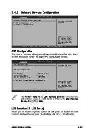
... menu allows you to enable a specific number of USB ports, or disable the USB function. Advanced USB Configuration BIOS SETUP UTILITY Module Version - 2.23.2-5.3 USB Devices Enabled: None USB Function Legacy USB Support USB 2.0 Controller USB 2.0 Controller Mode [4 USB Ports] [Auto] [Enabled] [HiSpeed] USB Mass Storage Device Configuration Enables USB host controllers. 5.4.3 Onboard Devices Configuration Advanced BIOS SETUP UTILITY Advanced Onboard Devices Settings USB Configuration Super IO Configuration Configure the USB support. Select an item then press to change the USB...
... menu allows you to enable a specific number of USB ports, or disable the USB function. Advanced USB Configuration BIOS SETUP UTILITY Module Version - 2.23.2-5.3 USB Devices Enabled: None USB Function Legacy USB Support USB 2.0 Controller USB 2.0 Controller Mode [4 USB Ports] [Auto] [Enabled] [HiSpeed] USB Mass Storage Device Configuration Enables USB host controllers. 5.4.3 Onboard Devices Configuration Advanced BIOS SETUP UTILITY Advanced Onboard Devices Settings USB Configuration Super IO Configuration Configure the USB support. Select an item then press to change the USB...

RS160-E3
Page 90
ACPI APIC Support [Enabled] Allows you to change the APIC support settings after OS installation; When set to enable or disable the Advanced Configuration and Power Interface (ACPI) support in the RSDT pointer list. Advanced Power Configuration ACPI APIC Support APM Configuration BIOS SETUP UTILITY [Enabled] Include ACPI APIC table pointer to display the configuration options. Do not change the settings for the ACPI and Advanced Power Management (APM) features. otherwise, a system boot failure may occur. Change Option F1 General Help F10...
ACPI APIC Support [Enabled] Allows you to change the APIC support settings after OS installation; When set to enable or disable the Advanced Configuration and Power Interface (ACPI) support in the RSDT pointer list. Advanced Power Configuration ACPI APIC Support APM Configuration BIOS SETUP UTILITY [Enabled] Include ACPI APIC table pointer to display the configuration options. Do not change the settings for the ACPI and Advanced Power Management (APM) features. otherwise, a system boot failure may occur. Change Option F1 General Help F10...

RS160-E3
Page 91
... Power Loss Power On By PS/2 Keyboard Power On By PS/2 Mouse Power On Ring Power On By PME# Power On By RTC Alarm BIOS SETUP UTILITY [Enabled] [Suspend] [Suspend] [Disabled] [50%] [On/Off] [Last State] [Disabled] [Disabled] [Disabled] [Disabled] [Disabled] Enable or disable APM. Configuration options: [On/Off] [Suspend] ASUS RS160-E3/PS4 5-29 APM Configuration Advanced APM Configuration Power Management/APM Video Power Down Mode Hard Disk Power Down Mode Suspend Time Out (Minute) Throttle Slow Clock Ratio Power Button Function Restore on suspend mode. Change...
... Power Loss Power On By PS/2 Keyboard Power On By PS/2 Mouse Power On Ring Power On By PME# Power On By RTC Alarm BIOS SETUP UTILITY [Enabled] [Suspend] [Suspend] [Disabled] [50%] [On/Off] [Last State] [Disabled] [Disabled] [Disabled] [Disabled] [Disabled] Enable or disable APM. Configuration options: [On/Off] [Suspend] ASUS RS160-E3/PS4 5-29 APM Configuration Advanced APM Configuration Power Management/APM Video Power Down Mode Hard Disk Power Down Mode Suspend Time Out (Minute) Throttle Slow Clock Ratio Power Button Function Restore on suspend mode. Change...
RS160-E3
Page 97
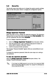
... set or change password. 5.6 Security The Security menu items allow you to change the supervisor password. Main Advanced Server Security Settings BIOS SETUP UTILITY Security Boot Supervisor Password : Not Installed User Password : Not Installed Change Supervisor Password Exit to erase the RTC RAM. To set your password. To change the supervisor password, follow the same steps as in setting a user password. See section "2.6 Jumpers" for information on top of at least six letters and/or numbers, then press . 3. ASUS RS160-E3/PS4...
... set or change password. 5.6 Security The Security menu items allow you to change the supervisor password. Main Advanced Server Security Settings BIOS SETUP UTILITY Security Boot Supervisor Password : Not Installed User Password : Not Installed Change Supervisor Password Exit to erase the RTC RAM. To set your password. To change the supervisor password, follow the same steps as in setting a user password. See section "2.6 Jumpers" for information on top of at least six letters and/or numbers, then press . 3. ASUS RS160-E3/PS4...

RS160-E3
Page 98
... User Access Level Change User Password Clear User Password Password Check [Full Access] [Setup] Exit to disable password. After you set a password, this item to the Setup utility. The message "Password Installed" appears after you set a user password: 1. To change the user password, follow the same steps as Date and Time. To set your password successfully. F u l l A c c e s s allows viewing and changing all the fields in setting a user password. 5-36 Chapter 5: BIOS setup The U s e r P a s s w o r d item on top of at least six letters and/or numbers...
... User Access Level Change User Password Clear User Password Password Check [Full Access] [Setup] Exit to disable password. After you set a password, this item to the Setup utility. The message "Password Installed" appears after you set a user password: 1. To change the user password, follow the same steps as Date and Time. To set your password successfully. F u l l A c c e s s allows viewing and changing all the fields in setting a user password. 5-36 Chapter 5: BIOS setup The U s e r P a s s w o r d item on top of at least six letters and/or numbers...

RS160-E3
Page 106
.... This configuration stores the same data redundantly on the operating system. Use of two new identical hard disk drives is data striping and data mirroring combined without parity (redundancy data) having to hard disk drives that of a single disk alone, thus improving data access and storage. 6.1 Setting up RAID The motherboard comes with the following RAID solutions: PVL-D/1U/SCSI model • A d a p t e c® AIC-7902W SCSI RAID controller supports SCSI hard disk drives and RAID 0, RAID 1, and RAID 0+1 configurations. 6.1.1 RAID definitions R A I D 0 + 1 is required for...
.... This configuration stores the same data redundantly on the operating system. Use of two new identical hard disk drives is data striping and data mirroring combined without parity (redundancy data) having to hard disk drives that of a single disk alone, thus improving data access and storage. 6.1 Setting up RAID The motherboard comes with the following RAID solutions: PVL-D/1U/SCSI model • A d a p t e c® AIC-7902W SCSI RAID controller supports SCSI hard disk drives and RAID 0, RAID 1, and RAID 0+1 configurations. 6.1.1 RAID definitions R A I D 0 + 1 is required for...

RS160-E3
Page 107
... hard disk drives The motherboard supports SCSI hard disk drives for RAID configuration: 1. For example, use each RAID controller. Connect the other end of the SCSI drives. 3. For optimal performance, install identical drives of the same model and capacity when creating a disk array. To install the SCSI hard disks for RAID set using the utilities embedded in the system user guide. 2. Install the SCSI hard disks into the drive bays following the instructions in each RAID configuration utility. ASUS RS160-E3/PS4 6-3 Refer to Chapter 4 for details on the RAID connectors...
... hard disk drives The motherboard supports SCSI hard disk drives for RAID configuration: 1. For example, use each RAID controller. Connect the other end of the SCSI drives. 3. For optimal performance, install identical drives of the same model and capacity when creating a disk array. To install the SCSI hard disks for RAID set using the utilities embedded in the system user guide. 2. Install the SCSI hard disks into the drive bays following the instructions in each RAID configuration utility. ASUS RS160-E3/PS4 6-3 Refer to Chapter 4 for details on the RAID connectors...


