
RS160-E3
Page 13
...bit/133MHz 3V PCI-X slots (on a riser card) 1 x low-profile 64-bit 133MHz 3V PCI-X slots* 1 x mini-PCI socket for ASUS Server Management Board Storage 4 x 3.5-inch hot-swappable SCSI HDD bays 1 x slim optical drive Front panel 2 x USB 2.0 ports Power switch ...controller supports: - 2 x SCSI channels with EM64T technology, plus other latest technologies through the chipsets onboard. 1.2 System specifications The ASUS RS160-E3/PS4 is supported) with Extended Memory 64-bit Technology (EM64T) Supports Enhanced Intel SpeedStep Technology (EIST) Supports Intel Hyper-Threading Technology Memory...
...bit/133MHz 3V PCI-X slots (on a riser card) 1 x low-profile 64-bit 133MHz 3V PCI-X slots* 1 x mini-PCI socket for ASUS Server Management Board Storage 4 x 3.5-inch hot-swappable SCSI HDD bays 1 x slim optical drive Front panel 2 x USB 2.0 ports Power switch ...controller supports: - 2 x SCSI channels with EM64T technology, plus other latest technologies through the chipsets onboard. 1.2 System specifications The ASUS RS160-E3/PS4 is supported) with Extended Memory 64-bit Technology (EM64T) Supports Enhanced Intel SpeedStep Technology (EIST) Supports Intel Hyper-Threading Technology Memory...

RS160-E3
Page 15
The power and reset buttons, LED indicators, location switch, optical drive, and two USB ports are located on the motherboard. ASUS RS160-E3/PS4 1-5 external SCSI port Expansion slot LAN port1 LAN port2 VGA port Serial port USB ports PS/2 keyboard port PS/2 mouse port Rear fans AC power ...
The power and reset buttons, LED indicators, location switch, optical drive, and two USB ports are located on the motherboard. ASUS RS160-E3/PS4 1-5 external SCSI port Expansion slot LAN port1 LAN port2 VGA port Serial port USB ports PS/2 keyboard port PS/2 mouse port Rear fans AC power ...

RS160-E3
Page 17
... RED Blinking LDE2 GREEN Blinking Description SCSI HDD power ON SCSI HDD failure RAID reset Read/write data into the SCSI HDD HDD status LED2 ASUS RS160-E3/PS4 1-7 no incoming event ASWM detects a system problem; (Log in normal condition;
... RED Blinking LDE2 GREEN Blinking Description SCSI HDD power ON SCSI HDD failure RAID reset Read/write data into the SCSI HDD HDD status LED2 ASUS RS160-E3/PS4 1-7 no incoming event ASWM detects a system problem; (Log in normal condition;

RS160-E3
Page 21
... place. 4. Make sure that the side markings on the cover (two on the chassis. 2. Lift the cover from the front panel. 2. Side markings Grooves 3. Thumbscrews ASUS RS160-E3/PS4 2-3
... place. 4. Make sure that the side markings on the cover (two on the chassis. 2. Lift the cover from the front panel. 2. Side markings Grooves 3. Thumbscrews ASUS RS160-E3/PS4 2-3

RS160-E3
Page 23
... CPU. This thermal grease should come with the CPU package. 7. Apply the thermal interface material (thermal grease) to secure the CPU. Marked corner (gold arrow) ASUS RS160-E3/PS4 2-5 The CPU fits only in place. DO NOT force the CPU into the socket until it is locked. 6. Carefully insert the CPU into the socket...
... CPU. This thermal grease should come with the CPU package. 7. Apply the thermal interface material (thermal grease) to secure the CPU. Marked corner (gold arrow) ASUS RS160-E3/PS4 2-5 The CPU fits only in place. DO NOT force the CPU into the socket until it is locked. 6. Carefully insert the CPU into the socket...

RS160-E3
Page 25
... from the same vendor. 2.3 System memory 2.3.1 Overview The motherboard comes with the same CAS latency. Refer to the DDR2 Qualified Vendors List on the ASUS web site. • Due to support 240-pin DDR2 modules. Mode DIMM_B4 DIMM_A4 DIMM_B3 DIMM_A3 DIMM_B2 DIMM_A2 DIMM_B1 DIMM_A1 Single-channel Dual-channel Populated with DIMM ASUS RS160-E3/PS4 2-7
... from the same vendor. 2.3 System memory 2.3.1 Overview The motherboard comes with the same CAS latency. Refer to the DDR2 Qualified Vendors List on the ASUS web site. • Due to support 240-pin DDR2 modules. Mode DIMM_B4 DIMM_A4 DIMM_B3 DIMM_A3 DIMM_B2 DIMM_A2 DIMM_B1 DIMM_A1 Single-channel Dual-channel Populated with DIMM ASUS RS160-E3/PS4 2-7

RS160-E3
Page 27
Release a drive tray by pushing the spring lock to secure the hard disk drive. 1 2 4. Use two screws on the tray, then secure it with four screws. ASUS RS160-E3/PS4 2-9 The drive tray ejects slightly after you pull out the lever. 2. Each side has three holes to fit different types of the drive tray holes. Place a hard disk drive on each side to the right, then pulling the tray lever outward. Take note of hard disk drives. Firmly hold the tray lever and pull the drive tray out of the bay. 3. 2.4 Hot-swap hard disk drives To install a hot-swap HDD: 1.
Release a drive tray by pushing the spring lock to secure the hard disk drive. 1 2 4. Use two screws on the tray, then secure it with four screws. ASUS RS160-E3/PS4 2-9 The drive tray ejects slightly after you pull out the lever. 2. Each side has three holes to fit different types of the drive tray holes. Place a hard disk drive on each side to the right, then pulling the tray lever outward. Take note of hard disk drives. Firmly hold the tray lever and pull the drive tray out of the bay. 3. 2.4 Hot-swap hard disk drives To install a hot-swap HDD: 1.

RS160-E3
Page 29
... cards To install a short expansion card: 1. Firmly hold the riser card bracket, then pull it from the PCI-X slot on the 64-bit expansion slot. ASUS RS160-E3/PS4 2-11 Use a Phillips (cross) screwdriver to remove the screw that secures the slot metal cover. 4. Remove the screw that secures the riser card to the...
... cards To install a short expansion card: 1. Firmly hold the riser card bracket, then pull it from the PCI-X slot on the 64-bit expansion slot. ASUS RS160-E3/PS4 2-11 Use a Phillips (cross) screwdriver to remove the screw that secures the slot metal cover. 4. Remove the screw that secures the riser card to the...
RS160-E3
Page 31
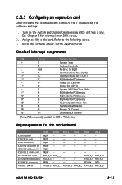
...# - - - - - PIRQA# - - - - - AIC-7902W SCSI contrl. PIRQH# - - - - - Install the software drivers for ISA or PCI devices. PXH2_A_0 PXH2_A_1 - - REQ1H# GNT1# PXH1_B_0 PXH1_B_1 PXH1_B_2 PXH1_B_3 PXH1_B_0 PXH1_B_0 ASUS RS160-E3/PS4 2-13 PCIX slot 1 (64-bit) INTA# INTB# INTC# INTD# REQ# GNT# PIRQC# - - - - - ICH5R USB UHCI contrl. #1 ICH5R USB UHCI contrl.#2 ICH5R USB 2.0 EHCI contrl. PIRQC...
...# - - - - - PIRQA# - - - - - AIC-7902W SCSI contrl. PIRQH# - - - - - Install the software drivers for ISA or PCI devices. PXH2_A_0 PXH2_A_1 - - REQ1H# GNT1# PXH1_B_0 PXH1_B_1 PXH1_B_2 PXH1_B_3 PXH1_B_0 PXH1_B_0 ASUS RS160-E3/PS4 2-13 PCIX slot 1 (64-bit) INTA# INTB# INTC# INTD# REQ# GNT# PIRQC# - - - - - ICH5R USB UHCI contrl. #1 ICH5R USB UHCI contrl.#2 ICH5R USB 2.0 EHCI contrl. PIRQC...

RS160-E3
Page 33
2-15 ASUS RS160-E3/PS4 USB 2.0 cable to front panel board 20-pin front panel cable to front panel board IDE cable to optical drive 30.5cm (12in) SCSI cable ...
2-15 ASUS RS160-E3/PS4 USB 2.0 cable to front panel board 20-pin front panel cable to front panel board IDE cable to optical drive 30.5cm (12in) SCSI cable ...

RS160-E3
Page 35
... following components: 1. To uninstall a fan or pair of fans, until it fits in a screw-less design. Carefully insert the fan, or pair of system fans: 1. ASUS RS160-E3/PS4 2-17 This section tells how to replace defective components. To install a fan or pair of the compartment. Power supply module 3. Hold the both sides on...
... following components: 1. To uninstall a fan or pair of fans, until it fits in a screw-less design. Carefully insert the fan, or pair of system fans: 1. ASUS RS160-E3/PS4 2-17 This section tells how to replace defective components. To install a fan or pair of the compartment. Power supply module 3. Hold the both sides on...

RS160-E3
Page 37
Use a Phillips screwdriver (cross) to release the top cover from the chassis. 4. ASUS RS160-E3/PS4 2-19 Loosen the two thunbscrews on the rear panel to remove the screw on each end of the bay. Firmly hold the tray level and pull all the drive trays out of the top cover. 2. Firmly hold the cover and slide it toward the rear panel for about half an inch until it is disengaged from the chassis. 3. 2.7.3 Optical drive To uninstall the slim optical drive: 1.
Use a Phillips screwdriver (cross) to release the top cover from the chassis. 4. ASUS RS160-E3/PS4 2-19 Loosen the two thunbscrews on the rear panel to remove the screw on each end of the bay. Firmly hold the tray level and pull all the drive trays out of the top cover. 2. Firmly hold the cover and slide it toward the rear panel for about half an inch until it is disengaged from the chassis. 3. 2.7.3 Optical drive To uninstall the slim optical drive: 1.

RS160-E3
Page 39
ASUS RS160-E3/PS4 2-21 Use a Phillips screwdriver (cross) to remove the screw that secure the optical drive to its metal bracket. 5. Carefully slide the optical drive inward for about half an inch, then lift it out of the bay. 7. Remove the screws that secures the drive. 6.
ASUS RS160-E3/PS4 2-21 Use a Phillips screwdriver (cross) to remove the screw that secure the optical drive to its metal bracket. 5. Carefully slide the optical drive inward for about half an inch, then lift it out of the bay. 7. Remove the screws that secures the drive. 6.

RS160-E3
Page 43
... rail pair. 9. When properly installed, the rack rails appear as shown. Find the r e a r 1 U s p a c e that corresponds to the f r o n t 1 U s p a c e where you wish to secure the rear end. 8. ASUS RS160-E3/PS4 3-3 3.3 Attaching the rails to the rack To attach the rails to attach the second rail pair. Align the front end holes of space (1U) on...
... rail pair. 9. When properly installed, the rack rails appear as shown. Find the r e a r 1 U s p a c e that corresponds to the f r o n t 1 U s p a c e where you wish to secure the rear end. 8. ASUS RS160-E3/PS4 3-3 3.3 Attaching the rails to the rack To attach the rails to attach the second rail pair. Align the front end holes of space (1U) on...

RS160-E3
Page 47
... 1. Backplane SMBus connector (6-1 pin BPSMB1) 11. Auxiliary panel connector (20-pin AUX_PANEL1) Page 4-9 4-9 4-10 4-11 4-12 4-12 4-13 4-13 4-14 4-14 4-14 4-15 4-16 4-17 ASUS RS160-E3/PS4 4-3 Zero-Channel RAID socket 5. Keyboard power (3-pin KBPWR1) 5. Mini-PCI socket Page 4-2 4-2 4-2 4-2 4-2 Jumpers 1. Hard disk activity LED connector (4-pin HDLED1) 6. Power supply SMBus connector (5-pin...
... 1. Backplane SMBus connector (6-1 pin BPSMB1) 11. Auxiliary panel connector (20-pin AUX_PANEL1) Page 4-9 4-9 4-10 4-11 4-12 4-12 4-13 4-13 4-14 4-14 4-14 4-15 4-16 4-17 ASUS RS160-E3/PS4 4-3 Zero-Channel RAID socket 5. Keyboard power (3-pin KBPWR1) 5. Mini-PCI socket Page 4-2 4-2 4-2 4-2 4-2 Jumpers 1. Hard disk activity LED connector (4-pin HDLED1) 6. Power supply SMBus connector (5-pin...

RS160-E3
Page 49
... condition or in reduced power mode). PVL-D/1U/SCSI ® PVL-D/1U/SCSI FM_CPU setting FM_CPU1 3 2 DC mode (Default) 2 1 PWM FM_CPU2 2 1 DC mode (Default) 3 2 PWM 3. 2. ASUS RS160-E3/PS4 4-5 otherwise, the system would not power up the system from S4 sleep mode (no power to wake up . • If you are using Windows 2000...
... condition or in reduced power mode). PVL-D/1U/SCSI ® PVL-D/1U/SCSI FM_CPU setting FM_CPU1 3 2 DC mode (Default) 2 1 PWM FM_CPU2 2 1 DC mode (Default) 3 2 PWM 3. 2. ASUS RS160-E3/PS4 4-5 otherwise, the system would not power up the system from S4 sleep mode (no power to wake up . • If you are using Windows 2000...

RS160-E3
Page 51
... to enable or disable the onboard Broadcom® BCM5721 Gigabit LAN1 controller. PVL-D/1U/SCSI ® LAN2_EN1 2 1 Enable (Default) PVL-D/1U/SCSI LAN2_EN setting 3 2 Disable ASUS RS160-E3/PS4 4-7 PVL-D/1U/SCSI ® LAN1_EN1 2 1 Enable (Default) PVL-D/1U/SCSI LAN1_EN setting 3 2 Disable 7. Set to pins 1-2 to activate the Gigabit LAN feature. Set to pins...
... to enable or disable the onboard Broadcom® BCM5721 Gigabit LAN1 controller. PVL-D/1U/SCSI ® LAN2_EN1 2 1 Enable (Default) PVL-D/1U/SCSI LAN2_EN setting 3 2 Disable ASUS RS160-E3/PS4 4-7 PVL-D/1U/SCSI ® LAN1_EN1 2 1 Enable (Default) PVL-D/1U/SCSI LAN1_EN setting 3 2 Disable 7. Set to pins 1-2 to activate the Gigabit LAN feature. Set to pins...

RS160-E3
Page 53
... insertion when you must configure the second drive as a slave device by setting its jumper accordingly. PVL-D/1U/SCSI ® PVL-D/1U/SCSI IDE connectors ASUS RS160-E3/PS4 SEC_IDE PIN 1 PRI_IDE PIN 1 NOTE: Orient the red markings (usually zigzag) on the connector is removed to the hard disk documentation for the jumper settings...
... insertion when you must configure the second drive as a slave device by setting its jumper accordingly. PVL-D/1U/SCSI ® PVL-D/1U/SCSI IDE connectors ASUS RS160-E3/PS4 SEC_IDE PIN 1 PRI_IDE PIN 1 NOTE: Orient the red markings (usually zigzag) on the connector is removed to the hard disk documentation for the jumper settings...

RS160-E3
Page 55
... a point-to-point configuration). When an SE device is attached, the bus defaults to 15 devices) PVL-D/SCSI SCSI connection example 68-pin Female Terminator ASUS RS160-E3/PS4 4-11 one for each of 15 devices as shown. With Ultra320 devices, the SCSI bus platform performs at full Ultra320 speeds (up to an SE...
... a point-to-point configuration). When an SE device is attached, the bus defaults to 15 devices) PVL-D/SCSI SCSI connection example 68-pin Female Terminator ASUS RS160-E3/PS4 4-11 one for each of 15 devices as shown. With Ultra320 devices, the SCSI bus platform performs at full Ultra320 speeds (up to an SE...

RS160-E3
Page 57
... REAR_FAN1 CPU_FAN2 FRNT_FAN1 FRNT_FAN2 PVL-D/1U/SCSI Fan connectors REAR_FAN1 GND +12V Rotation FRNT_FAN1 GND +12V Rotation REAR_FAN2 Rotation +12V GND FRNT_FAN2 GND +12V Rotation ASUS RS160-E3/PS4 4-13 7. Serial port connector (10-1 pin COM2) This connector is purchased separately. 8. Do not forget to connect the fan cables to the fan connectors on...
... REAR_FAN1 CPU_FAN2 FRNT_FAN1 FRNT_FAN2 PVL-D/1U/SCSI Fan connectors REAR_FAN1 GND +12V Rotation FRNT_FAN1 GND +12V Rotation REAR_FAN2 Rotation +12V GND FRNT_FAN2 GND +12V Rotation ASUS RS160-E3/PS4 4-13 7. Serial port connector (10-1 pin COM2) This connector is purchased separately. 8. Do not forget to connect the fan cables to the fan connectors on...


