User Guide
Page 13
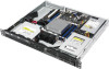
... or SATA signal, NGFF2 only supports SATA signal. Gray SATA port will be disabled when M.2 is a 1U barebone server system featuring the ASUS P10S-M-DC server board. 1.3 System specifications The ASUS RS100-E9-PI2 is used with SATA signal) Intel® RSTe (For Linux/Windows) (Supports Software RAID 0, 1) HDD Bays Networking Graphic I /O 4 x USB 3.0 ports (Front...
... or SATA signal, NGFF2 only supports SATA signal. Gray SATA port will be disabled when M.2 is a 1U barebone server system featuring the ASUS P10S-M-DC server board. 1.3 System specifications The ASUS RS100-E9-PI2 is used with SATA signal) Intel® RSTe (For Linux/Windows) (Supports Software RAID 0, 1) HDD Bays Networking Graphic I /O 4 x USB 3.0 ports (Front...
User Guide
Page 15
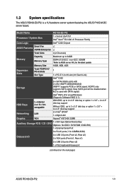
ASUS RS100-E9-PI2 1-5 The I/O shield with easily accessible features. PS/2 mouse/keyboard combo port LAN port 3* Serial port AC power socket USB 2.0 port USB 3.0 port Q-Code LED LAN ... for the rear panel connectors on the front panel. 1.4 Front panel features This barebone server has a simple yet stylish front panel with openings for an ASUS ASMB8-iKVM controller card only. Refer to any added expansion cards. The power and reset buttons, LED indicators, optical drive, and two USB ports are...
ASUS RS100-E9-PI2 1-5 The I/O shield with easily accessible features. PS/2 mouse/keyboard combo port LAN port 3* Serial port AC power socket USB 2.0 port USB 3.0 port Q-Code LED LAN ... for the rear panel connectors on the front panel. 1.4 Front panel features This barebone server has a simple yet stylish front panel with openings for an ASUS ASMB8-iKVM controller card only. Refer to any added expansion cards. The power and reset buttons, LED indicators, optical drive, and two USB ports are...

User Guide
Page 17
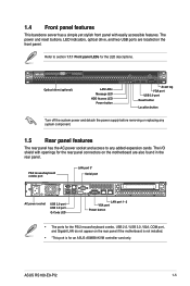
... Location LED LAN LEDs Display status Description ON System power ON OFF No activity Blinking Read/write data into the HDD OFF System is present ASUS RS100-E9-PI2 1-7
... Location LED LAN LEDs Display status Description ON System power ON OFF No activity Blinking Read/write data into the HDD OFF System is present ASUS RS100-E9-PI2 1-7

User Guide
Page 21
Side tabs ASUS RS100-E9-PI2 2-3 Position the cover on top of the chassis with the hooks aligned to the side tabs of the chassis. 2.1.2 Reinstalling the chassis cover To reinstall the chassis cover: 1.
Side tabs ASUS RS100-E9-PI2 2-3 Position the cover on top of the chassis with the hooks aligned to the side tabs of the chassis. 2.1.2 Reinstalling the chassis cover To reinstall the chassis cover: 1.
User Guide
Page 23
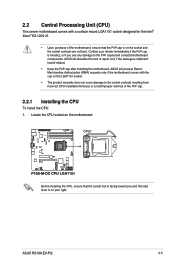
ASUS will process Return Merchandise Authorization (RMA) requests only if the motherboard comes with a surface mount LGA1151 socket designed for the Intel® Xeon® E3-... PnP cap. 2.2.1 Installing the CPU To install the CPU: 1. Before installing the CPU, ensure that the PnP cap is on the motherboard. Contact your right. ASUS RS100-E9-PI2 2-5 ASUS will shoulder the cost of repair only if the damage is missing, or if you and the load lever is on the LGA1151 socket. •...
ASUS will process Return Merchandise Authorization (RMA) requests only if the motherboard comes with a surface mount LGA1151 socket designed for the Intel® Xeon® E3-... PnP cap. 2.2.1 Installing the CPU To install the CPU: 1. Before installing the CPU, ensure that the PnP cap is on the motherboard. Contact your right. ASUS RS100-E9-PI2 2-5 ASUS will shoulder the cost of repair only if the damage is missing, or if you and the load lever is on the LGA1151 socket. •...

User Guide
Page 25
... edge of the CPU that it is toxic and inedible. The Thermal Interface Material is evenly spread in contact with pre-applied Thermal Interface Material. ASUS RS100-E9-PI2 Retention lock Load lever Retention tab 2-7 Insert the load lever under the retention lock (B) then push down the load lever (C). Skip this step if the...
... edge of the CPU that it is toxic and inedible. The Thermal Interface Material is evenly spread in contact with pre-applied Thermal Interface Material. ASUS RS100-E9-PI2 Retention lock Load lever Retention tab 2-7 Insert the load lever under the retention lock (B) then push down the load lever (C). Skip this step if the...

User Guide
Page 27
Reattach the screw and secure the airduct onto the motherboard. The fastener on the airduct should align with the screw hole on the motherboard. ASUS RS100-E9-PI2 2-9 Place the airduct over the heatsink. To install the airduct: 1. Locate and remove the screw from the motherboard. 2.
Reattach the screw and secure the airduct onto the motherboard. The fastener on the airduct should align with the screw hole on the motherboard. ASUS RS100-E9-PI2 2-9 Place the airduct over the heatsink. To install the airduct: 1. Locate and remove the screw from the motherboard. 2.

User Guide
Page 29
... in the motherboard package. • Refer to avoid damaging the DIMM. 3. Align a DIMM on the socket. Unlock a DIMM socket by pressing the retaining clip outward. ASUS RS100-E9-PI2 2-11 DO NOT force a DIMM into the socket. Hold the DIMM on a single clip DIMM socket 1. 2.3.3 Installing a DIMM on both ends of the DIMM simultaneously...
... in the motherboard package. • Refer to avoid damaging the DIMM. 3. Align a DIMM on the socket. Unlock a DIMM socket by pressing the retaining clip outward. ASUS RS100-E9-PI2 2-11 DO NOT force a DIMM into the socket. Hold the DIMM on a single clip DIMM socket 1. 2.3.3 Installing a DIMM on both ends of the DIMM simultaneously...
User Guide
Page 31
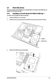
Remove the HDD drive tray and set aside. 3. Release the four screws that secure the HDD drive tray to the chassis and set aside. Both HDD bays can support 3.5-inch Serial ATA HDD. 2.4.1 Installing a 3.5-inch Serial ATA HDD to HDD bay 1 To install a 3.5-inch Serial ATA HDD to the system. HDD bay 1 HDD drive tray ASUS RS100-E9-PI2 2-13 2.4 Hard disk drives The server chassis has two HDD bays for installing HDDs to HDD bay 1: 1. Locate the HDD bay 1 in the chassis. 2.
Remove the HDD drive tray and set aside. 3. Release the four screws that secure the HDD drive tray to the chassis and set aside. Both HDD bays can support 3.5-inch Serial ATA HDD. 2.4.1 Installing a 3.5-inch Serial ATA HDD to HDD bay 1 To install a 3.5-inch Serial ATA HDD to the system. HDD bay 1 HDD drive tray ASUS RS100-E9-PI2 2-13 2.4 Hard disk drives The server chassis has two HDD bays for installing HDDs to HDD bay 1: 1. Locate the HDD bay 1 in the chassis. 2.

User Guide
Page 33
Secure the 3.5-inch SATA HDD and HDD drive tray assembly to the HDD bay 1 using the screws removed in place. Ensure that the HDD drive tray is seated securely in step 2. Place and orient the HDD drive tray and 3.5-inch SATA HDD assembly as shown. ASUS RS100-E9-PI2 HDD bay 1 HDD drive tray 2-15 7. SATA signal cable SATA power cable 8.
Secure the 3.5-inch SATA HDD and HDD drive tray assembly to the HDD bay 1 using the screws removed in place. Ensure that the HDD drive tray is seated securely in step 2. Place and orient the HDD drive tray and 3.5-inch SATA HDD assembly as shown. ASUS RS100-E9-PI2 HDD bay 1 HDD drive tray 2-15 7. SATA signal cable SATA power cable 8.

User Guide
Page 35
... 1 the screw holes on the SSD drive tray as shown. SSD 2 SSD drive tray 8. 5. Ensure that the SSD drive tray is seated securely in step 3. ASUS RS100-E9-PI2 2-17 Prepare the SSD drive tray. 6. Carefully place the 2.5-inch SSD and the SSD drive tray assembly into HDD bay 1. 9. Place and orient two 2.5-inch...
... 1 the screw holes on the SSD drive tray as shown. SSD 2 SSD drive tray 8. 5. Ensure that the SSD drive tray is seated securely in step 3. ASUS RS100-E9-PI2 2-17 Prepare the SSD drive tray. 6. Carefully place the 2.5-inch SSD and the SSD drive tray assembly into HDD bay 1. 9. Place and orient two 2.5-inch...
User Guide
Page 37
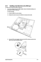
To remove the ODD: 1.a Locate the ODD in the server chassis. 1.b Release the screw that secures the ODD to HDD bay 2. inch Sertial ATA HDD to the chassis and set aside. Then, remove the ODD as shown. ASUS RS100-E9-PI2 2-19 HDD bay 2 1.c Push the ODD outward slightly to HDD bay 2: 1. If you have an Optical Disc Drive (ODD) installed, remove it first before installing a 3.5- 2.4.3 Installing a hard disk drive to the HDD bay 2 To install a 3.5-inch Serial ATA HDD to disconnect the SATA and power cable from the ODD.
To remove the ODD: 1.a Locate the ODD in the server chassis. 1.b Release the screw that secures the ODD to HDD bay 2. inch Sertial ATA HDD to the chassis and set aside. Then, remove the ODD as shown. ASUS RS100-E9-PI2 2-19 HDD bay 2 1.c Push the ODD outward slightly to HDD bay 2: 1. If you have an Optical Disc Drive (ODD) installed, remove it first before installing a 3.5- 2.4.3 Installing a hard disk drive to the HDD bay 2 To install a 3.5-inch Serial ATA HDD to disconnect the SATA and power cable from the ODD.

User Guide
Page 39
5. Secure the 3.5-inch SATA HDD and HDD drive tray assembly to the 3.5-inch HDD. Ensure that the HDD drive tray is seated securely in step 2. Connect the SATA signal cable and the power cable from the power supply to the HDD bay 2 using the bundled set of screws (as shown. 7. Secure the 3.5-inch Serial ATA HDD into the HDD drive tray using the screws removed in place. Use an L-type SATA connector to connect the 3.5-inch SATA HDD to the motherboard. 8. ASUS RS100-E9-PI2 2-21 Place and orient the HDD drive tray and 3.5-inch SATA HDD assembly as shown). 6.
5. Secure the 3.5-inch SATA HDD and HDD drive tray assembly to the 3.5-inch HDD. Ensure that the HDD drive tray is seated securely in step 2. Connect the SATA signal cable and the power cable from the power supply to the HDD bay 2 using the bundled set of screws (as shown. 7. Secure the 3.5-inch Serial ATA HDD into the HDD drive tray using the screws removed in place. Use an L-type SATA connector to connect the 3.5-inch SATA HDD to the motherboard. 8. ASUS RS100-E9-PI2 2-21 Place and orient the HDD drive tray and 3.5-inch SATA HDD assembly as shown). 6.
User Guide
Page 41
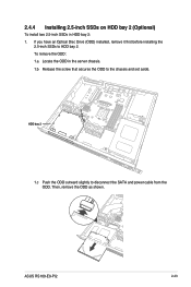
2.4.4 Installing 2.5-inch SSDs on HDD bay 2 (Optional) To install two 2.5-inch SSDs in the server chassis. 1.b Release the screw that secures the ODD to the chassis and set aside. ASUS RS100-E9-PI2 2-23 To remove the ODD: 1.a Locate the ODD in HDD bay 2: 1. HDD bay 2 1.c Push the ODD outward slightly to HDD bay 2. If you have an Optical Disc Drive (ODD) installed, remove it first before installing the 2.5-inch SSDs to disconnect the SATA and power cable from the ODD. Then, remove the ODD as shown.
2.4.4 Installing 2.5-inch SSDs on HDD bay 2 (Optional) To install two 2.5-inch SSDs in the server chassis. 1.b Release the screw that secures the ODD to the chassis and set aside. ASUS RS100-E9-PI2 2-23 To remove the ODD: 1.a Locate the ODD in HDD bay 2: 1. HDD bay 2 1.c Push the ODD outward slightly to HDD bay 2. If you have an Optical Disc Drive (ODD) installed, remove it first before installing the 2.5-inch SSDs to disconnect the SATA and power cable from the ODD. Then, remove the ODD as shown.

User Guide
Page 43
To secure the ODD Dummy to the SSDs. You may install either one ODD or two 2.5-inch SSDs to the reserved space in place. Ensure that the SSD drive tray is seated securely in HDD bay 2. ASUS RS100-E9-PI2 2-25 Connect the SATA signal cable and power cable to HDD bay 2, use the two bundled screws (B) as shown. 7. Secure the 2.5-inch SSDs and SSD drive tray assembly to section 2.7.3 for more information. Refer to the HDD bay 2 using the bundled screw (A). 6.
To secure the ODD Dummy to the SSDs. You may install either one ODD or two 2.5-inch SSDs to the reserved space in place. Ensure that the SSD drive tray is seated securely in HDD bay 2. ASUS RS100-E9-PI2 2-25 Connect the SATA signal cable and power cable to HDD bay 2, use the two bundled screws (B) as shown. 7. Secure the 2.5-inch SSDs and SSD drive tray assembly to section 2.7.3 for more information. Refer to the HDD bay 2 using the bundled screw (A). 6.

User Guide
Page 45
Install the expansion card to the bracket (A) and secure the expansion card with the screw removed in step 3 (B). 5. Install the expansion card to the riser card (C). 6. Enusre that the golden connectors of the riser card are seated firmly in step 2. Secure the bracket using the screw removed in place. 7. ASUS RS100-E9-PI2 2-27 4. Install the expansion card and the riser card assembly into the PCIE connector on the motherboard (D).
Install the expansion card to the bracket (A) and secure the expansion card with the screw removed in step 3 (B). 5. Install the expansion card to the riser card (C). 6. Enusre that the golden connectors of the riser card are seated firmly in step 2. Secure the bracket using the screw removed in place. 7. ASUS RS100-E9-PI2 2-27 4. Install the expansion card and the riser card assembly into the PCIE connector on the motherboard (D).

User Guide
Page 47
Align and insert the M.2 card into the M.2 connector on the motherboard. 2. Prepare the M.2 card. 4. Secure the M.2 card to the motherboard using the screw removed in step 2. Locate the M.2 (NGFF) card connector on the motherboard. 5. 2.5.3 Installing M.2 (NGFF) cards To install an M.2 (NGFF) card: 1. Remove the screw from the motherboard. 3. ASUS RS100-E9-PI2 2-29
Align and insert the M.2 card into the M.2 connector on the motherboard. 2. Prepare the M.2 card. 4. Secure the M.2 card to the motherboard using the screw removed in step 2. Locate the M.2 (NGFF) card connector on the motherboard. 5. 2.5.3 Installing M.2 (NGFF) cards To install an M.2 (NGFF) card: 1. Remove the screw from the motherboard. 3. ASUS RS100-E9-PI2 2-29

User Guide
Page 49
... FRNT_FAN2 and FRNT_FAN3. Optical disk drive (optional) 4. Secure the fans onto the chassis using the provided screws. 2. System fans 2. ASUS RS100-E9-PI2 2-31 Position the system fans to install optional components into the system. ASUS ASMB8-iKVM (optional) Ensure that the system is turned off before removing any components. 2.7.1 System fans To install the...
... FRNT_FAN2 and FRNT_FAN3. Optical disk drive (optional) 4. Secure the fans onto the chassis using the provided screws. 2. System fans 2. ASUS RS100-E9-PI2 2-31 Position the system fans to install optional components into the system. ASUS ASMB8-iKVM (optional) Ensure that the system is turned off before removing any components. 2.7.1 System fans To install the...

User Guide
Page 51
Install the expansion card to the bracket (C) and secure the expansion card with the screw removed in place. Install the expansion card to the riser card (E). 7. Enusre that the golden connectors of the riser card are seated firmly in step 4 (D). 6. Remove the screw from the metal cover (A) and remove the metal cover (B) from the chassis. 4. ASUS RS100-E9-PI2 2-33 3. Remove the screw to release the expansion card bracket from the bracket. 5. Install the expansion card and the riser card assembly into the PCIE connector on the motherboard (F).
Install the expansion card to the bracket (C) and secure the expansion card with the screw removed in place. Install the expansion card to the riser card (E). 7. Enusre that the golden connectors of the riser card are seated firmly in step 4 (D). 6. Remove the screw from the metal cover (A) and remove the metal cover (B) from the chassis. 4. ASUS RS100-E9-PI2 2-33 3. Remove the screw to release the expansion card bracket from the bracket. 5. Install the expansion card and the riser card assembly into the PCIE connector on the motherboard (F).

User Guide
Page 53
You may install either one ODD or two 2.5-inch SSDs to the optical disk drive before sliding the optical disk drive all the way into the drive slot. ASUS RS100-E9-PI2 2-35 Align the screw hole of the ODD bracket with a screw. Secure the ODD with the screw hole on the chassis. Connect the ODD cable to the reserved space in HDD bay 2. 2.7.3 Optical disk drive (optional) To install the optical disk drive: 1. Optical disk drive slot 2. Refer to section 2.4.4 for more information. Slide the optical disk drive into the drive slot. 3.
You may install either one ODD or two 2.5-inch SSDs to the optical disk drive before sliding the optical disk drive all the way into the drive slot. ASUS RS100-E9-PI2 2-35 Align the screw hole of the ODD bracket with a screw. Secure the ODD with the screw hole on the chassis. Connect the ODD cable to the reserved space in HDD bay 2. 2.7.3 Optical disk drive (optional) To install the optical disk drive: 1. Optical disk drive slot 2. Refer to section 2.4.4 for more information. Slide the optical disk drive into the drive slot. 3.


