User Guide
Page 48
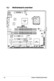
.../2KBMS T: Mouse B: Keyboard LAN_USB12 EATXPWR1 24.5cm (9.6in) ATX12V1 ISL 6312 COM1 VGA1 BCM 5721 BCM 5721 Intel 3200 MCH ® P5BV-M/RS100-E5 DDR2 DIMM_A1 (64 bit,240-pin module) LAN1 DDR2 DIMM_A2 (64 bit,240-pin module) LAN2 CR2032 3V Lithium Cell CMOS Power DDR2 DIMM_B1...LGA775 CPU_FAN1 CPUFAN_SET1 CHAFAN_SET1 BUZZ1 XGI Z9s SB_PWR1 REAR_FAN1 COM2 HDLED1 PCIE2 PCI3 PCI4 FLOPPY1 ASMB3 Super I/O 8Mb BIOS ICS 9LPRS918BKL Intel ICH7R ICH TPM1 AUX_PANEL1 USB34 RAID_SEL1 CLRTC1 RECOVERY1 PANEL1 SATA3 SATA1 SATA2 SATA4 PRI_IDE1 4-2 Chapter 4: Motherboard Information
.../2KBMS T: Mouse B: Keyboard LAN_USB12 EATXPWR1 24.5cm (9.6in) ATX12V1 ISL 6312 COM1 VGA1 BCM 5721 BCM 5721 Intel 3200 MCH ® P5BV-M/RS100-E5 DDR2 DIMM_A1 (64 bit,240-pin module) LAN1 DDR2 DIMM_A2 (64 bit,240-pin module) LAN2 CR2032 3V Lithium Cell CMOS Power DDR2 DIMM_B1...LGA775 CPU_FAN1 CPUFAN_SET1 CHAFAN_SET1 BUZZ1 XGI Z9s SB_PWR1 REAR_FAN1 COM2 HDLED1 PCIE2 PCI3 PCI4 FLOPPY1 ASMB3 Super I/O 8Mb BIOS ICS 9LPRS918BKL Intel ICH7R ICH TPM1 AUX_PANEL1 USB34 RAID_SEL1 CLRTC1 RECOVERY1 PANEL1 SATA3 SATA1 SATA2 SATA4 PRI_IDE1 4-2 Chapter 4: Motherboard Information

User Guide
Page 50
... as system passwords. The onboard button cell battery powers the RAM data in CMOS. Keep the cap on CLRTC jumper default position. After the CMOS clearance, reinstall the battery. ® P5BV-M/RS100-E5 CLRTC1 12 23 Normal (Default) P5BV-M/RS100-E5 Clear RTC RAM Clear CMOS • You do not help, remove the...data. Move the jumper cap from pins 1-2 (default) to overclocking. To erase the RTC RAM: 1. Removing the cap will cause system boot failure! Hold down and reboot the system so the BIOS can clear the CMOS memory of date, time, and system setup parameters by erasing the ...
... as system passwords. The onboard button cell battery powers the RAM data in CMOS. Keep the cap on CLRTC jumper default position. After the CMOS clearance, reinstall the battery. ® P5BV-M/RS100-E5 CLRTC1 12 23 Normal (Default) P5BV-M/RS100-E5 Clear RTC RAM Clear CMOS • You do not help, remove the...data. Move the jumper cap from pins 1-2 (default) to overclocking. To erase the RTC RAM: 1. Removing the cap will cause system boot failure! Hold down and reboot the system so the BIOS can clear the CMOS memory of date, time, and system setup parameters by erasing the ...
User Guide
Page 51
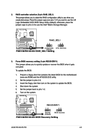
.... ® P5BV-M/RS100-E5 RAID_SEL1 12 23 LSI RAID ROM INTEL RAID ROM (Default) P5BV-M/RS100-E5 RAID_SEL1 Setting 3. RAID controller selection (3-pin RAID_SEL1) This jumper allows you to select the RAID configuration utility to update the BIOS. 4. Insert the floppy disk then turn on the system. ® P5BV-M/RS100-E5 RECOVERY1 12 23 Normal (Default) BIOS recovery P5BV-M/RS100-E5 BIOS Recovery Setting ASUS RS100-E5-PI2...
.... ® P5BV-M/RS100-E5 RAID_SEL1 12 23 LSI RAID ROM INTEL RAID ROM (Default) P5BV-M/RS100-E5 RAID_SEL1 Setting 3. RAID controller selection (3-pin RAID_SEL1) This jumper allows you to select the RAID configuration utility to update the BIOS. 4. Insert the floppy disk then turn on the system. ® P5BV-M/RS100-E5 RECOVERY1 12 23 Normal (Default) BIOS recovery P5BV-M/RS100-E5 BIOS Recovery Setting ASUS RS100-E5-PI2...
User Guide
Page 56
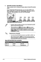
...using the Intel® Matrix Storage Technology or the LSI MegaRAID® utility embedded in the Intel® ICH7R Southbridge. ® P5BV-M/RS100-E5 SATA3 SATA1 SATA2 SATA4 GND RSATA_RXN2 RSATA_RXP2 GND RSATA_TXN2 RSATA_TXP2 GND GND RSATA_RXN1 RSATA_RXP1 GND RSATA_TXN1 RSATA_TXP1 GND GND RSATA_RXN3 RSATA_RXP3 GND RSATA_TXN3 ... SATA hard disk drive connections. In IDE mode, you intend to create a Serial ATA RAID set using the connectors in the BIOS to the table below for Serial ATA hard disk drives. Serial ATA connectors (7-pin SATA1-4) These connectors are set . •...
...using the Intel® Matrix Storage Technology or the LSI MegaRAID® utility embedded in the Intel® ICH7R Southbridge. ® P5BV-M/RS100-E5 SATA3 SATA1 SATA2 SATA4 GND RSATA_RXN2 RSATA_RXP2 GND RSATA_TXN2 RSATA_TXP2 GND GND RSATA_RXN1 RSATA_RXP1 GND RSATA_TXN1 RSATA_TXP1 GND GND RSATA_RXN3 RSATA_RXP3 GND RSATA_TXN3 ... SATA hard disk drive connections. In IDE mode, you intend to create a Serial ATA RAID set using the connectors in the BIOS to the table below for Serial ATA hard disk drives. Serial ATA connectors (7-pin SATA1-4) These connectors are set . •...
User Guide
Page 60
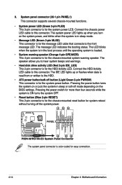
...; Message LED (Brown 2-pin MLED) This connector is for the system power button. The speaker allows you turn on the BIOS settings. Pressing the power button turns the system on or puts the system in sleep or soft-off mode depending on the system...button/soft-off the system power. 1 2 3 POWERLED+ GND POWERLEDMLED+ MLEDNC +5V GND GND SPKROUT ® P5BV-M/RS100-E5 PANEL1 HDLED+ HDLEDNMIBTN# GND POWERBTN# GND NC RESETBTN# GND 4 5 6 P5BV-M/RS100-E5 System Panel Connector The system panel connector is read from or written to this connector. The system power LED lights...
...; Message LED (Brown 2-pin MLED) This connector is for the system power button. The speaker allows you turn on the BIOS settings. Pressing the power button turns the system on or puts the system in sleep or soft-off mode depending on the system...button/soft-off the system power. 1 2 3 POWERLED+ GND POWERLEDMLED+ MLEDNC +5V GND GND SPKROUT ® P5BV-M/RS100-E5 PANEL1 HDLED+ HDLEDNMIBTN# GND POWERBTN# GND NC RESETBTN# GND 4 5 6 P5BV-M/RS100-E5 System Panel Connector The system panel connector is read from or written to this connector. The system power LED lights...


