User Guide
Page 1
Motherboard PRIME Z370-A Series
Motherboard PRIME Z370-A Series
User Guide
Page 3
...vi About this guide...vii PRIME Z370-A specifications summary ix Package contents...xiv Installation tools and components xv Chapter 1: Product Introduction 1.1 Motherboard overview 1-1 1.1.1 Before you proceed 1-1 1.1.2 Motherboard layout 1-2 1.1.3 Central Processing ... 2-3 2.1.3 Motherboard installation 2-5 2.1.4 DIMM installation 2-7 2.1.5 ATX power connection 2-8 2.1.6 SATA device connection 2-8 2.1.7 Front I/O connector 2-9 2.1.8 Expansion card installation 2-10 2.1.9 M.2 installation 2-11 2.1.10 ASUS fan holder installation 2-12 2.2 Motherboard rear and audio...
...vi About this guide...vii PRIME Z370-A specifications summary ix Package contents...xiv Installation tools and components xv Chapter 1: Product Introduction 1.1 Motherboard overview 1-1 1.1.1 Before you proceed 1-1 1.1.2 Motherboard layout 1-2 1.1.3 Central Processing ... 2-3 2.1.3 Motherboard installation 2-5 2.1.4 DIMM installation 2-7 2.1.5 ATX power connection 2-8 2.1.6 SATA device connection 2-8 2.1.7 Front I/O connector 2-9 2.1.8 Expansion card installation 2-10 2.1.9 M.2 installation 2-11 2.1.10 ASUS fan holder installation 2-12 2.2 Motherboard rear and audio...
User Guide
Page 6
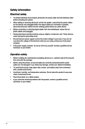
...circuitry. • Avoid dust, humidity, and temperature extremes. Do not place the product in your retailer. Operation safety • Before installing the motherboard and adding devices on a stable surface. • If you encounter technical problems with the package. • Before using the product, ensure all... the power cables for the devices are unplugged before you add a device. • Before connecting or removing signal cables from the motherboard, ensure that came with the product, contact a qualified service technician or your area. If you are not sure about the voltage ...
...circuitry. • Avoid dust, humidity, and temperature extremes. Do not place the product in your retailer. Operation safety • Before installing the motherboard and adding devices on a stable surface. • If you encounter technical problems with the package. • Before using the product, ensure all... the power cables for the devices are unplugged before you add a device. • Before connecting or removing signal cables from the motherboard, ensure that came with the product, contact a qualified service technician or your area. If you are not sure about the voltage ...
User Guide
Page 7
... Detailed descriptions of the standard package. Chapter 4: RAID Support This chapter describes the RAID configurations. ASUS website The ASUS website (www.asus.com) provides updated information on the motherboard. 2. These documents are not part of the BIOS parameters are also provided. 4. It includes ...description of the motherboard and the new technology it supports. Chapter 3: BIOS Setup This chapter tells how to ...
... Detailed descriptions of the standard package. Chapter 4: RAID Support This chapter describes the RAID configurations. ASUS website The ASUS website (www.asus.com) provides updated information on the motherboard. 2. These documents are not part of the BIOS parameters are also provided. 4. It includes ...description of the motherboard and the new technology it supports. Chapter 3: BIOS Setup This chapter tells how to ...
User Guide
Page 14
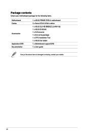
Package contents Check your motherboard package for the following items. Motherboard Cables Accessories Application DVD Documentation 1 x ASUS PRIME Z370-A motherboard 3 x Serial ATA 6.0 Gb/s cables 1 x ASUS SLI HB BRIDGE (2-WAY-M) 1 x ASUS Q-Shield 1 x Q-Connector 1 x M.2 screw package 1 x CPU Installation Tool 1 x ASUS fan holder 1 x Motherboard support DVD 1 x User guide If any of the above items is damaged or missing, contact your retailer. xiv
Package contents Check your motherboard package for the following items. Motherboard Cables Accessories Application DVD Documentation 1 x ASUS PRIME Z370-A motherboard 3 x Serial ATA 6.0 Gb/s cables 1 x ASUS SLI HB BRIDGE (2-WAY-M) 1 x ASUS Q-Shield 1 x Q-Connector 1 x M.2 screw package 1 x CPU Installation Tool 1 x ASUS fan holder 1 x Motherboard support DVD 1 x User guide If any of the above items is damaged or missing, contact your retailer. xiv
User Guide
Page 15
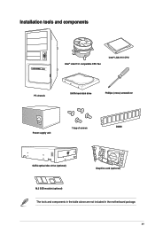
xv Installation tools and components Intel® LGA1151 compatible CPU Fan Intel® LGA1151 CPU PC chassis SATA hard disk drive Phillips (cross) screwdriver Power supply unit 1 bag of screws DIMM SATA optical disc drive (optional) Graphics card (optional) M.2 SSD module (optional) The tools and components in the table above are not included in the motherboard package.
xv Installation tools and components Intel® LGA1151 compatible CPU Fan Intel® LGA1151 CPU PC chassis SATA hard disk drive Phillips (cross) screwdriver Power supply unit 1 bag of screws DIMM SATA optical disc drive (optional) Graphics card (optional) M.2 SSD module (optional) The tools and components in the table above are not included in the motherboard package.
User Guide
Page 17
ASUS PRIME Z370-A Series 1-1 Chapter 1 Chapter 1: Product Introduction Product Introduction 1 1.1 Motherboard overview 1.1.1 Before you proceed Take note of the following precautions before you install or remove any component. • Before handling components, use a grounded... any component, place it on a grounded antistatic pad or in the bag that came with the component. • Before you install motherboard components or change any motherboard settings. • Unplug the power cord from the wall socket before touching any component, ensure that the ATX power supply is switched...
ASUS PRIME Z370-A Series 1-1 Chapter 1 Chapter 1: Product Introduction Product Introduction 1 1.1 Motherboard overview 1.1.1 Before you proceed Take note of the following precautions before you install or remove any component. • Before handling components, use a grounded... any component, place it on a grounded antistatic pad or in the bag that came with the component. • Before you install motherboard components or change any motherboard settings. • Unplug the power cord from the wall socket before touching any component, ensure that the ATX power supply is switched...
User Guide
Page 18
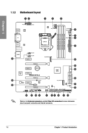
1.1.2 Motherboard layout Chapter 1 Refer to 1.1.9 Internal connectors and 2.2.1 Rear I/O connection for more information about rear panel connectors and internal connectors. 1-2 Chapter 1: Product Introduction
1.1.2 Motherboard layout Chapter 1 Refer to 1.1.9 Internal connectors and 2.2.1 Rear I/O connection for more information about rear panel connectors and internal connectors. 1-2 Chapter 1: Product Introduction
User Guide
Page 20
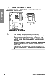
... immediately if the PnP cap is shipment/ transit-related. • Keep the cap after installing the motherboard. ASUS will process Return Merchandise Authorization (RMA) requests only if the motherboard comes with a surface mount LGA1151 socket designed for the 8th Generation Intel® Core™ processors.... • Ensure that all power cables are not bent. Chapter 1 1.1.3 Central Processing Unit (CPU) The motherboard comes with the cap on the socket and the socket contacts are unplugged before installing the CPU. • Upon purchase of the PnP...
... immediately if the PnP cap is shipment/ transit-related. • Keep the cap after installing the motherboard. ASUS will process Return Merchandise Authorization (RMA) requests only if the motherboard comes with a surface mount LGA1151 socket designed for the 8th Generation Intel® Core™ processors.... • Ensure that all power cables are not bent. Chapter 1 1.1.3 Central Processing Unit (CPU) The motherboard comes with the cap on the socket and the socket contacts are unplugged before installing the CPU. • Upon purchase of the PnP...
User Guide
Page 21
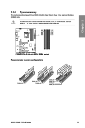
A DDR4 module is notched differently from a DDR, DDR2, or DDR3 module. DO NOT install a DDR, DDR2, or DDR3 memory module to the DDR4 slot. Recommended memory configurations ASUS PRIME Z370-A Series 1-5 Chapter 1 1.1.4 System memory The motherboard comes with four DDR4 (Double Data Rate 4) Dual Inline Memory Modules (DIMM) slots.
A DDR4 module is notched differently from a DDR, DDR2, or DDR3 module. DO NOT install a DDR, DDR2, or DDR3 memory module to the DDR4 slot. Recommended memory configurations ASUS PRIME Z370-A Series 1-5 Chapter 1 1.1.4 System memory The motherboard comes with four DDR4 (Double Data Rate 4) Dual Inline Memory Modules (DIMM) slots.
User Guide
Page 22
... are using a 32-bit Windows® OS. The system maps the total size of accessing information from the higher-sized channel is dependent on the motherboard. c) For more on its Serial Presence Detect (SPD), which is the standard way of the lower-sized channel for the latest QVL. 1-6 Chapter 1:..., we recommend that you want to get the correct memory modules. • Visit the ASUS website for the dual-channel configuration. Check with the same CAS Latency. com/kb/929605/en-us. • This motherboard does not support DIMMs made up of 512 Mb (64 MB) chips or less (Memory...
... are using a 32-bit Windows® OS. The system maps the total size of accessing information from the higher-sized channel is dependent on the motherboard. c) For more on its Serial Presence Detect (SPD), which is the standard way of the lower-sized channel for the latest QVL. 1-6 Chapter 1:..., we recommend that you want to get the correct memory modules. • Visit the ASUS website for the dual-channel configuration. Check with the same CAS Latency. com/kb/929605/en-us. • This motherboard does not support DIMMs made up of 512 Mb (64 MB) chips or less (Memory...
User Guide
Page 23
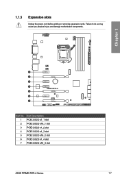
Chapter 1 Slot No. 1 2 3 4 5 6 7 Slot Description PCIE 3.0/2.0 x1_1 slot PCIE 3.0/2.0 x16_1 slot PCIE 3.0/2.0 x1_2 slot PCIE 3.0/2.0 x1_3 slot PCIE 3.0/2.0 x16_2 slot PCIE 3.0/2.0 x1_4 slot PCIE 3.0/2.0 x16_3 slot ASUS PRIME Z370-A Series 1-7 1.1.5 Expansion slots Unplug the power cord before adding or removing expansion cards. Failure to do so may cause you physical injury and damage motherboard components.
Chapter 1 Slot No. 1 2 3 4 5 6 7 Slot Description PCIE 3.0/2.0 x1_1 slot PCIE 3.0/2.0 x16_1 slot PCIE 3.0/2.0 x1_2 slot PCIE 3.0/2.0 x1_3 slot PCIE 3.0/2.0 x16_2 slot PCIE 3.0/2.0 x1_4 slot PCIE 3.0/2.0 x16_3 slot ASUS PRIME Z370-A Series 1-7 1.1.5 Expansion slots Unplug the power cord before adding or removing expansion cards. Failure to do so may cause you physical injury and damage motherboard components.
User Guide
Page 24
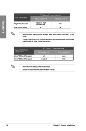
... recommended) N/A x8 x8 • We recommend that you provide sufficient power when running CrossFireX™ or SLI® mode. • Connect chassis fans to the motherboard chassis fan connectors when using multiple graphics cards for better thermal environment. Hyper M.2 X16 card configuration 2 Intel® SSD on CPU support 3 Intel® SSD...
... recommended) N/A x8 x8 • We recommend that you provide sufficient power when running CrossFireX™ or SLI® mode. • Connect chassis fans to the motherboard chassis fan connectors when using multiple graphics cards for better thermal environment. Hyper M.2 X16 card configuration 2 Intel® SSD on CPU support 3 Intel® SSD...
User Guide
Page 25
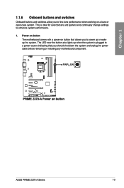
... 1.1.6 Onboard buttons and switches Onboard buttons and switches allow you should shut down the system and unplug the power cable before removing or installing any motherboard component. This is plugged to power up or wake up when the system is ideal for overclockers and gamers who continually change settings to fine... button that allows you to a power source indicating that you to enhance system performance. 1. The LED near the button also lights up the system. ASUS PRIME Z370-A Series 1-9 Power-on button The motherboard comes with a power-on a bare or open-case system.
... 1.1.6 Onboard buttons and switches Onboard buttons and switches allow you should shut down the system and unplug the power cable before removing or installing any motherboard component. This is plugged to power up or wake up when the system is ideal for overclockers and gamers who continually change settings to fine... button that allows you to a power source indicating that you to enhance system performance. 1. The LED near the button also lights up the system. ASUS PRIME Z370-A Series 1-9 Power-on button The motherboard comes with a power-on a bare or open-case system.
User Guide
Page 26
... to its default settings. • We recommend that are not compatible with ones recommended in the Memory QVL (Qualified Vendors Lists) at www.asus.com. • If you download and update to memory tuning requirement, the system automatically reboots when each timing set of the DRAM LED increases... lights up due to boot during the tuning process, the system continues memory tuning after using the MemOK! Replace the DIMMs with the motherboard may cause system boot failure. button Installing DIMMs that you turn off the computer and unplug the power cord for about 30 seconds for...
... to its default settings. • We recommend that are not compatible with ones recommended in the Memory QVL (Qualified Vendors Lists) at www.asus.com. • If you download and update to memory tuning requirement, the system automatically reboots when each timing set of the DRAM LED increases... lights up due to boot during the tuning process, the system continues memory tuning after using the MemOK! Replace the DIMMs with the motherboard may cause system boot failure. button Installing DIMMs that you turn off the computer and unplug the power cord for about 30 seconds for...
User Guide
Page 28
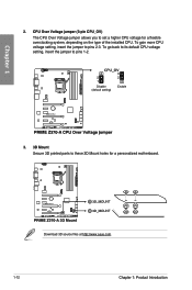
Chapter 1 3. 3D Mount Secure 3D printed parts to pins 1-2. To go back to its default CPU voltage setting, insert the jumper to these 3D Mount holes for a flexible overclocking system, depending on the type of the installed CPU. CPU Over Voltage jumper (3-pin CPU_OV) The CPU Over Voltage jumper allows you to pins 2-3. To gain more CPU voltage setting, insert the jumper to set a higher CPU voltage for a personalized motherboard. Download 3D source files at http://www.asus.com. 1-12 Chapter 1: Product Introduction 2.
Chapter 1 3. 3D Mount Secure 3D printed parts to pins 1-2. To go back to its default CPU voltage setting, insert the jumper to these 3D Mount holes for a flexible overclocking system, depending on the type of the installed CPU. CPU Over Voltage jumper (3-pin CPU_OV) The CPU Over Voltage jumper allows you to pins 2-3. To gain more CPU voltage setting, insert the jumper to set a higher CPU voltage for a personalized motherboard. Download 3D source files at http://www.asus.com. 1-12 Chapter 1: Product Introduction 2.
User Guide
Page 29
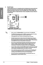
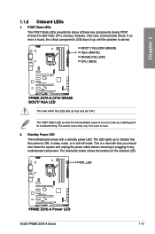
If an error is found, the critical component's LED stays lit up until the problem is ON, in sleep mode, or in any motherboard component. The POST State LEDs provide the most probable cause of the onboard LED. The illustration below shows the location of an error code as a ... the status of these key components during POST (Power-On Self-Test): CPU, memory modules, VGA card, and hard disk drives. Standby Power LED The motherboard comes with a standby power LED. This is a reminder that the system is solved. ASUS PRIME Z370-A Series 1-13
If an error is found, the critical component's LED stays lit up until the problem is ON, in sleep mode, or in any motherboard component. The POST State LEDs provide the most probable cause of the onboard LED. The illustration below shows the location of an error code as a ... the status of these key components during POST (Power-On Self-Test): CPU, memory modules, VGA card, and hard disk drives. Standby Power LED The motherboard comes with a standby power LED. This is a reminder that the system is solved. ASUS PRIME Z370-A Series 1-13

User Guide
Page 31
Connect one end of the front panel audio I /O module that you connect a high-definition front panel audio module to this connector to this connector. Chapter 1 2. We recommend that supports HD Audio. ASUS PRIME Z370-A Series 1-15 Front panel audio connector (10-1 pin AAFP) This connector is for a chassis-mounted front panel audio I /O module cable to avail of the motherboard's high-definition audio capability.
Connect one end of the front panel audio I /O module that you connect a high-definition front panel audio module to this connector to this connector. Chapter 1 2. We recommend that supports HD Audio. ASUS PRIME Z370-A Series 1-15 Front panel audio connector (10-1 pin AAFP) This connector is for a chassis-mounted front panel audio I /O module cable to avail of the motherboard's high-definition audio capability.
User Guide
Page 33
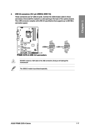
Doing so will damage the motherboard! ASUS PRIME Z370-A Series 1-17 Connect the USB module cable to these connectors, then install the module to the USB connectors. The USB 2.0 module is purchased separately. USB 2.0 connectors (10-1 pin USB910; DO NOT connect a 1394 cable to a slot opening at the back of the system chassis. This USB connector complies with USB 2.0 specification that supports up to 480 Mb/s connection speed. USB1112) These connectors are for USB 2.0 ports. Chapter 1 4.
Doing so will damage the motherboard! ASUS PRIME Z370-A Series 1-17 Connect the USB module cable to these connectors, then install the module to the USB connectors. The USB 2.0 module is purchased separately. USB 2.0 connectors (10-1 pin USB910; DO NOT connect a 1394 cable to a slot opening at the back of the system chassis. This USB connector complies with USB 2.0 specification that supports up to 480 Mb/s connection speed. USB1112) These connectors are for USB 2.0 ports. Chapter 1 4.
User Guide
Page 34
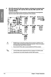
Do not place jumper caps on the motherboard, ensuring that the CPU fan cable is securely installed to the CPU fan connector. • The CPU_FAN connector supports the CPU fan of maximum 1A (... the ground pin of your water cooling kit to the AIO_PUMP connector. 1-18 Chapter 1: Product Introduction Insufficient air flow inside the system may damage the motherboard components.
Do not place jumper caps on the motherboard, ensuring that the CPU fan cable is securely installed to the CPU fan connector. • The CPU_FAN connector supports the CPU fan of maximum 1A (... the ground pin of your water cooling kit to the AIO_PUMP connector. 1-18 Chapter 1: Product Introduction Insufficient air flow inside the system may damage the motherboard components.


