
Users Manual English
Page 15
... wall socket before touching any component, ensure that the ATX power supply is switched off or the power cord is detached from the power supply. ASUS PRIME X570-PRO 1-1
... wall socket before touching any component, ensure that the ATX power supply is switched off or the power cord is detached from the power supply. ASUS PRIME X570-PRO 1-1

Users Manual English
Page 17
...) 23. 8-pin power plug LED Page 1-18 1-19 1-17 1-4 1-10 1-4 1-8 1-20 1-14 1-21 1-18 1-13 1-9 1-16 1-11 1-20 1-14 1-15 1-15 1-19 1-12 1-12 1-22 ASUS PRIME X570-PRO 1-3
...) 23. 8-pin power plug LED Page 1-18 1-19 1-17 1-4 1-10 1-4 1-8 1-20 1-14 1-21 1-18 1-13 1-9 1-16 1-11 1-20 1-14 1-15 1-15 1-19 1-12 1-12 1-22 ASUS PRIME X570-PRO 1-3

Users Manual English
Page 19
... operation frequency is dependent on its Serial Presence Detect (SPD), which is the standard way of the same version or data code (D/C) from a memory module. ASUS PRIME X570-PRO 1-5 Check with the same CAS Latency. For an optimum compatibility, we recommend that you install memory modules of accessing information from the same vendor.
... operation frequency is dependent on its Serial Presence Detect (SPD), which is the standard way of the same version or data code (D/C) from a memory module. ASUS PRIME X570-PRO 1-5 Check with the same CAS Latency. For an optimum compatibility, we recommend that you install memory modules of accessing information from the same vendor.

Users Manual English
Page 21
... running CrossFireX or SLI® mode. • Connect chassis fans to the motherboard chassis fan connectors when using multiple graphics cards for better thermal environment. ASUS PRIME X570-PRO 1-7
... running CrossFireX or SLI® mode. • Connect chassis fans to the motherboard chassis fan connectors when using multiple graphics cards for better thermal environment. ASUS PRIME X570-PRO 1-7
Users Manual English
Page 23
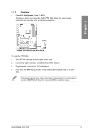
... cord and turn ON the computer. 4. Turn OFF the computer and unplug the power cord. 2. Use a metal object such as date, time, and system passwords. ASUS PRIME X570-PRO 1-9 If the steps above do not help, remove the onboard battery and short the two pins again to re-enter data. Hold down the key... clear the CMOS RTC RAM data of the system setup information such as a screwdriver to short the two pins. 3. +3V_BAT GND Chapter 1 1.1.7 Headers 1. CLRTC PIN 1 PRIME X570-PRO Clear RTC RAM To erase the RTC RAM: 1. After clearing the CMOS, reinstall the battery.
... cord and turn ON the computer. 4. Turn OFF the computer and unplug the power cord. 2. Use a metal object such as date, time, and system passwords. ASUS PRIME X570-PRO 1-9 If the steps above do not help, remove the onboard battery and short the two pins again to re-enter data. Hold down the key... clear the CMOS RTC RAM data of the system setup information such as a screwdriver to short the two pins. 3. +3V_BAT GND Chapter 1 1.1.7 Headers 1. CLRTC PIN 1 PRIME X570-PRO Clear RTC RAM To erase the RTC RAM: 1. After clearing the CMOS, reinstall the battery.

Users Manual English
Page 25
ADD_GEN2 PIN 1 PRIME X570-PRO ADD_GEN2 header The addressable gen 2 RGB header supports WS2812B addressable RGB LED strips (5V/ Data/Ground), with the 12V header on the motherboard. • The ... supply is switched off or the power cord is for individually addressable RGB WS2812B LED strips or WS2812B based LED strips. +5V Data Ground Chapter 1 3. ASUS PRIME X570-PRO 1-11 Addressable RGB Gen 2 header (4-1 pin ADD_GEN2) This connector is detached from the power supply.
ADD_GEN2 PIN 1 PRIME X570-PRO ADD_GEN2 header The addressable gen 2 RGB header supports WS2812B addressable RGB LED strips (5V/ Data/Ground), with the 12V header on the motherboard. • The ... supply is switched off or the power cord is for individually addressable RGB WS2812B LED strips or WS2812B based LED strips. +5V Data Ground Chapter 1 3. ASUS PRIME X570-PRO 1-11 Addressable RGB Gen 2 header (4-1 pin ADD_GEN2) This connector is detached from the power supply.

Users Manual English
Page 27
ASUS PRIME X570-PRO 1-13 AMD Serial ATA 6 Gb/s connectors (7-pin SATA6G_1-6) These connectors...for details. If you can create a RAID 0, RAID 1, and RAID 10 configuration through the onboard AMD X570 chipset. Refer to [AHCI] by default. SATA6G_5 GND RSATA_TXP5 RSATA_TXN5 GND RSATA_RXN5 RSATA_RXP5 GND SATA6G_6 GND RSATA_TXP6 RSATA_TXN6... RSATA_RXP4 GND SATA6G_1 GND RSATA_TXP1 RSATA_TXN1 GND RSATA_RXN1 RSATA_RXP1 GND SATA6G_2 GND RSATA_TXP2 RSATA_TXN2 GND RSATA_RXN2 RSATA_RXP2 GND PRIME X570-PRO SATA 6 Gb/s connectors • These connectors are set the SATA Mode in the BIOS to Serial...
ASUS PRIME X570-PRO 1-13 AMD Serial ATA 6 Gb/s connectors (7-pin SATA6G_1-6) These connectors...for details. If you can create a RAID 0, RAID 1, and RAID 10 configuration through the onboard AMD X570 chipset. Refer to [AHCI] by default. SATA6G_5 GND RSATA_TXP5 RSATA_TXN5 GND RSATA_RXN5 RSATA_RXP5 GND SATA6G_6 GND RSATA_TXP6 RSATA_TXN6... RSATA_RXP4 GND SATA6G_1 GND RSATA_TXP1 RSATA_TXN1 GND RSATA_RXN1 RSATA_RXP1 GND SATA6G_2 GND RSATA_TXP2 RSATA_TXN2 GND RSATA_RXN2 RSATA_RXP2 GND PRIME X570-PRO SATA 6 Gb/s connectors • These connectors are set the SATA Mode in the BIOS to Serial...

Users Manual English
Page 29
....0 connectors Never connect a 1394 cable to a slot opening at the back of your motherboard's critical components and connected devices. T_SENSOR GND PIN 1 SENSOR IN PRIME X570-PRO T_SENSOR connector ASUS PRIME X570-PRO 1-15 Thermal sensor connector (2-pin T_SENSOR) This connector is for USB 2.0 ports. USB34) These connectors are for the thermistor cable that supports up to...
....0 connectors Never connect a 1394 cable to a slot opening at the back of your motherboard's critical components and connected devices. T_SENSOR GND PIN 1 SENSOR IN PRIME X570-PRO T_SENSOR connector ASUS PRIME X570-PRO 1-15 Thermal sensor connector (2-pin T_SENSOR) This connector is for USB 2.0 ports. USB34) These connectors are for the thermistor cable that supports up to...

Users Manual English
Page 31
...CHA_FAN2 CHA FAN PWM CHA FAN IN B CHA FAN PWR GND C D G W_PUMP+ GND PUMP PWR PUMP IN PUMP PWM E F G PRIME X570-PRO Fan connectors • DO NOT forget to connect the fan cables to the CPU_FAN and/or CPU_OPT header(s). • W_PUMP+ function support depends ... Speed Q-Fan Controlled Q-Fan Controlled Q-Fan Controlled Q-Fan Controlled Q-Fan Controlled Full Speed Full Speed Shared Control A A B B ASUS PRIME X570-PRO 1-17 Header CPU_FAN CPU_OPT CHA_FAN1 CHA_FAN2 CHA_FAN3 AIO_PUMP W_PUMP+ Max. Insufficient air flow inside the system may damage the motherboard components. water...
...CHA_FAN2 CHA FAN PWM CHA FAN IN B CHA FAN PWR GND C D G W_PUMP+ GND PUMP PWR PUMP IN PUMP PWM E F G PRIME X570-PRO Fan connectors • DO NOT forget to connect the fan cables to the CPU_FAN and/or CPU_OPT header(s). • W_PUMP+ function support depends ... Speed Q-Fan Controlled Q-Fan Controlled Q-Fan Controlled Q-Fan Controlled Q-Fan Controlled Full Speed Full Speed Shared Control A A B B ASUS PRIME X570-PRO 1-17 Header CPU_FAN CPU_OPT CHA_FAN1 CHA_FAN2 CHA_FAN3 AIO_PUMP W_PUMP+ Max. Insufficient air flow inside the system may damage the motherboard components. water...

Users Manual English
Page 33
COM PIN 1 PRIME X570-PRO Serial port (COM) connector The COM module is for a serial (COM) port. LED connector (13-pin LED1_CON) The LED connector is purchased separately. 13. Chapter 1 RXD DTR DSR CTS DCD TXD GND RTS RI 12. Serial port connector (10-1 pin COM) This connector is for connecting an RGB Card under the rear I/O cover. LED1_CON PRIME X570-PRO LED_CON ASUS PRIME X570-PRO 1-19 Connect the serial port module cable to this connector, then install the module to a slot opening at the back of the system chassis.
COM PIN 1 PRIME X570-PRO Serial port (COM) connector The COM module is for a serial (COM) port. LED connector (13-pin LED1_CON) The LED connector is purchased separately. 13. Chapter 1 RXD DTR DSR CTS DCD TXD GND RTS RI 12. Serial port connector (10-1 pin COM) This connector is for connecting an RGB Card under the rear I/O cover. LED1_CON PRIME X570-PRO LED_CON ASUS PRIME X570-PRO 1-19 Connect the serial port module cable to this connector, then install the module to a slot opening at the back of the system chassis.

Users Manual English
Page 35
The M.2 SSD module is purchased separately. M.2 sockets (M.2_1; ASUS PRIME X570-PRO 1-21 M.2_2) These sockets allow you to install M.2 SSD modules. Chapter 1 16. A M.2_1(SOCKET3) 22110 2280 2260 2242 B A M.2_2(SOCKET3) B 22110 2280 2260 2242 PRIME X570-PRO M.2 sockets • For 3rd Gen AMD Ryzen™ Processors, the M.2_1 socket supports PCIe 4.0 x4 mode and SATA mode...
The M.2 SSD module is purchased separately. M.2 sockets (M.2_1; ASUS PRIME X570-PRO 1-21 M.2_2) These sockets allow you to install M.2 SSD modules. Chapter 1 16. A M.2_1(SOCKET3) 22110 2280 2260 2242 B A M.2_2(SOCKET3) B 22110 2280 2260 2242 PRIME X570-PRO M.2 sockets • For 3rd Gen AMD Ryzen™ Processors, the M.2_1 socket supports PCIe 4.0 x4 mode and SATA mode...

Users Manual English
Page 37
The motherboard layout may vary with AMD AM4 processors. DO NOT force the CPU into the socket to prevent bending the connectors on the socket and damaging the CPU! Ensure you use a CPU designed for all models. 2.1.1 CPU installation The AMD AM4 socket is compatible with models, but the installation steps are for reference only. Chapter 2 ASUS PRIME X570-PRO 2-1 Chapter 2: Basic Installation Basic Installation 2 2.1 Building your PC system The diagrams in only one correct orientation. The CPU fits in this section are the same for the AM4 socket.
The motherboard layout may vary with AMD AM4 processors. DO NOT force the CPU into the socket to prevent bending the connectors on the socket and damaging the CPU! Ensure you use a CPU designed for all models. 2.1.1 CPU installation The AMD AM4 socket is compatible with models, but the installation steps are for reference only. Chapter 2 ASUS PRIME X570-PRO 2-1 Chapter 2: Basic Installation Basic Installation 2 2.1 Building your PC system The diagrams in only one correct orientation. The CPU fits in this section are the same for the AM4 socket.

Users Manual English
Page 39
Do not remove the plate on the bottom. ASUS PRIME X570-PRO 2-3 CPU heatsink and fan assembly Type 2 Chapter 2 When using this type of CPU fan, remove the screws and the retention module only.
Do not remove the plate on the bottom. ASUS PRIME X570-PRO 2-3 CPU heatsink and fan assembly Type 2 Chapter 2 When using this type of CPU fan, remove the screws and the retention module only.

Users Manual English
Page 41
Doing so can damage the motherboard. Chapter 2 DO NOT over tighten the screws! 2.1.3 Motherboard installation 1. Place nine (9) screws into the chassis, ensuring that its rear I/O ports are aligned to the chassis. Place the motherboard into the holes indicated by circles to secure the motherboard to the chassis' rear I/O panel. 2. ASUS PRIME X570-PRO 2-5
Doing so can damage the motherboard. Chapter 2 DO NOT over tighten the screws! 2.1.3 Motherboard installation 1. Place nine (9) screws into the chassis, ensuring that its rear I/O ports are aligned to the chassis. Place the motherboard into the holes indicated by circles to secure the motherboard to the chassis' rear I/O panel. 2. ASUS PRIME X570-PRO 2-5

Users Manual English
Page 43
2.1.5 ATX power connection A Chapter 2 B OR AND • DO NOT connect the 4-pin power plug only, the motherboard may overheat under heavy usage. • Ensure to connect the 8-pin power plug, or both the 8-pin and 4-pin power plugs. ASUS PRIME X570-PRO 2-7
2.1.5 ATX power connection A Chapter 2 B OR AND • DO NOT connect the 4-pin power plug only, the motherboard may overheat under heavy usage. • Ensure to connect the 8-pin power plug, or both the 8-pin and 4-pin power plugs. ASUS PRIME X570-PRO 2-7

Users Manual English
Page 45
Push the connector until it clicks into place. To install USB 3.2 Gen 1 connector To install USB 2.0 connector USB 3.2 Gen 1 To install front panel audio connector USB 2.0 AAFP ASUS PRIME X570-PRO 2-9 Chapter 2 2.1.7 Front I/O connector To install the front panel connector To install USB 3.2 Gen 2 connector USB 3.2 Gen 2 This connector will only fit in one orientation.
Push the connector until it clicks into place. To install USB 3.2 Gen 1 connector To install USB 2.0 connector USB 3.2 Gen 1 To install front panel audio connector USB 2.0 AAFP ASUS PRIME X570-PRO 2-9 Chapter 2 2.1.7 Front I/O connector To install the front panel connector To install USB 3.2 Gen 2 connector USB 3.2 Gen 2 This connector will only fit in one orientation.

Users Manual English
Page 47
M.2_1 installation Chapter 2 ASUS PRIME X570-PRO 2-11 2.1.9 M.2 installation Supported M.2 type varies per motherboard.
M.2_1 installation Chapter 2 ASUS PRIME X570-PRO 2-11 2.1.9 M.2 installation Supported M.2 type varies per motherboard.

Users Manual English
Page 49
... panel connectors 1. USB 3.2 Gen 1 (up to 5Gbps) ports 8. USB 3.2 Gen 2 (up to USB 3.2 Gen 2 ports for faster and better performance from your USB 3.2 Gen 2 devices. ASUS PRIME X570-PRO 2-13 DisplayPort 3. Optical S/PDIF OUT port 7.
... panel connectors 1. USB 3.2 Gen 1 (up to 5Gbps) ports 8. USB 3.2 Gen 2 (up to USB 3.2 Gen 2 ports for faster and better performance from your USB 3.2 Gen 2 devices. ASUS PRIME X570-PRO 2-13 DisplayPort 3. Optical S/PDIF OUT port 7.

Users Manual English
Page 51
Chapter 2 2.2.2 Audio I/O connections Audio I/O ports Connect to Headphone and Mic Connect to Stereo Speakers Connect to 2-channel Speakers ASUS PRIME X570-PRO 2-15
Chapter 2 2.2.2 Audio I/O connections Audio I/O ports Connect to Headphone and Mic Connect to Stereo Speakers Connect to 2-channel Speakers ASUS PRIME X570-PRO 2-15

Users Manual English
Page 53
... (starting with a surge protector. 5. Connect the power cord to the power connector at the back of the BIOS setting. At power on self tests (POST). ASUS PRIME X570-PRO 2-17 Press the power button for the first time 1. System power 6. Chapter 2 2.3 Starting up . Ensure that is ON, press the power button for assistance. Monitor...
... (starting with a surge protector. 5. Connect the power cord to the power connector at the back of the BIOS setting. At power on self tests (POST). ASUS PRIME X570-PRO 2-17 Press the power button for the first time 1. System power 6. Chapter 2 2.3 Starting up . Ensure that is ON, press the power button for assistance. Monitor...


