
Users Manual English
Page 15
ASUS PRIME X470-PRO 1-1 Failure to do so may cause severe damage to avoid touching the ICs on them due to static electricity. • Hold components by the edges ...
ASUS PRIME X470-PRO 1-1 Failure to do so may cause severe damage to avoid touching the ICs on them due to static electricity. • Hold components by the edges ...
Users Manual English
Page 17
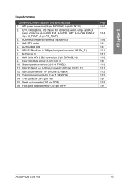
... 5Gbps) connector (20-1 pin U31G1_12) 12. Front panel audio connector (10-1 pin AAFP) Page 1-15 1-14 1-16 1-4 1-4 1-11 1-17 1-10 1-8 1-13 1-11 1-12 1-12 1-9 1-15 1-9 ASUS PRIME X470-PRO 1-3 water pump+, and AIO pump connectors (4-pin CPU_FAN, 4-pin CPU_OPT, 4-pin CHA_FAN1-3; 4-pin W_PUMP+, 4-pin AIO_PUMP) 3. ATX power connectors (24-pin EATXPWR; 8-pin EATX12V) 2. DDR4...
... 5Gbps) connector (20-1 pin U31G1_12) 12. Front panel audio connector (10-1 pin AAFP) Page 1-15 1-14 1-16 1-4 1-4 1-11 1-17 1-10 1-8 1-13 1-11 1-12 1-12 1-9 1-15 1-9 ASUS PRIME X470-PRO 1-3 water pump+, and AIO pump connectors (4-pin CPU_FAN, 4-pin CPU_OPT, 4-pin CHA_FAN1-3; 4-pin W_PUMP+, 4-pin AIO_PUMP) 3. ATX power connectors (24-pin EATXPWR; 8-pin EATX12V) 2. DDR4...
Users Manual English
Page 19
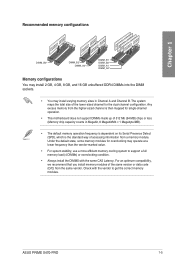
... operation frequency is dependent on its Serial Presence Detect (SPD), which is the standard way of the same version or data code (D/C) from a memory module. ASUS PRIME X470-PRO 1-5 The system maps the total size of the lower-sized channel for single-channel operation. • This motherboard does not support DIMMs made up of...
... operation frequency is dependent on its Serial Presence Detect (SPD), which is the standard way of the same version or data code (D/C) from a memory module. ASUS PRIME X470-PRO 1-5 The system maps the total size of the lower-sized channel for single-channel operation. • This motherboard does not support DIMMs made up of...

Users Manual English
Page 21
... running CrossFireX or SLI® mode. • Connect chassis fans to the motherboard chassis fan connectors when using multiple graphics cards for better thermal environment. ASUS PRIME X470-PRO 1-7
... running CrossFireX or SLI® mode. • Connect chassis fans to the motherboard chassis fan connectors when using multiple graphics cards for better thermal environment. ASUS PRIME X470-PRO 1-7

Users Manual English
Page 23
... L PORT1 R PORT2 R SENSE_SEND PORT2 L AAFP ® HD-audio-compliant pin definition PRIME X470-PRO Front panel audio connector We recommend that supports HD Audio. TPM PIN 1 ® PRIME X470-PRO TPM connector The TPM module is for a chassis-mounted front panel audio I/O module that you...motherboard's high-definition audio capability. 2. F_CLKRUN F_SERIRQ F_FRAME# F_LAD3 F_LAD2 F_LAD1 F_LAD0 +3VSB S_PCIRST#_TBD GND C_PCICLK_TPM +3V +3V ASUS PRIME X470-PRO 1-9 Front panel audio connector (10-1 pin AAFP) This connector is purchased separately. TPM connector (14-1 pin TPM) This connector...
... L PORT1 R PORT2 R SENSE_SEND PORT2 L AAFP ® HD-audio-compliant pin definition PRIME X470-PRO Front panel audio connector We recommend that supports HD Audio. TPM PIN 1 ® PRIME X470-PRO TPM connector The TPM module is for a chassis-mounted front panel audio I/O module that you...motherboard's high-definition audio capability. 2. F_CLKRUN F_SERIRQ F_FRAME# F_LAD3 F_LAD2 F_LAD1 F_LAD0 +3VSB S_PCIRST#_TBD GND C_PCICLK_TPM +3V +3V ASUS PRIME X470-PRO 1-9 Front panel audio connector (10-1 pin AAFP) This connector is purchased separately. TPM connector (14-1 pin TPM) This connector...

Users Manual English
Page 25
...connector (20-1 pin U31G1_12) This connector allows you to 5 Gb/s, faster charging time for additional USB 3.1 Gen 1 front or rear panel ports. ASUS PRIME X470-PRO 1-11 USB 3.1 Gen 2 (up to connect a USB 3.1 Gen 1 module for USB-chargeable devices, optimized power efficiency, and backward compatibility with...your existing USB devices. Chapter 1 U31G2_C1 SBU2 SBU1 CC1 VBUS RX1RX1+ GND TX1TX1+ VBUS VBUS TX2+ TX2GND RX2+ RX2GND DD+ CC2 ® PRIME X470-PRO USB 3.1 Gen 2 front panel connector 5. With an installed USB 3.1 Gen 1 module, you can enjoy all the benefits of USB 3.1 Gen...
...connector (20-1 pin U31G1_12) This connector allows you to 5 Gb/s, faster charging time for additional USB 3.1 Gen 1 front or rear panel ports. ASUS PRIME X470-PRO 1-11 USB 3.1 Gen 2 (up to connect a USB 3.1 Gen 1 module for USB-chargeable devices, optimized power efficiency, and backward compatibility with...your existing USB devices. Chapter 1 U31G2_C1 SBU2 SBU1 CC1 VBUS RX1RX1+ GND TX1TX1+ VBUS VBUS TX2+ TX2GND RX2+ RX2GND DD+ CC2 ® PRIME X470-PRO USB 3.1 Gen 2 front panel connector 5. With an installed USB 3.1 Gen 1 module, you can enjoy all the benefits of USB 3.1 Gen...

Users Manual English
Page 27
... LED lights up when you to the HDD. • System warning speaker (4-pin SPEAKER) This 4-pin connector is for the system power button. ASUS PRIME X470-PRO 1-13 Pressing the power switch for more than four seconds while the system is ON turns the system OFF. • Reset button (2-pin RESET)... in sleep or soft-off the system power. Connect the HDD Activity LED cable to this connector. RESET +PWR_LED* Requires an ATX power supply PRIME X470-PRO System panel connector • System power LED (2-pin or 3-1 pin PLED) The 2-pin or 3-1 pin connector is for the chassis-mounted reset...
... LED lights up when you to the HDD. • System warning speaker (4-pin SPEAKER) This 4-pin connector is for the system power button. ASUS PRIME X470-PRO 1-13 Pressing the power switch for more than four seconds while the system is ON turns the system OFF. • Reset button (2-pin RESET)... in sleep or soft-off the system power. Connect the HDD Activity LED cable to this connector. RESET +PWR_LED* Requires an ATX power supply PRIME X470-PRO System panel connector • System power LED (2-pin or 3-1 pin PLED) The 2-pin or 3-1 pin connector is for the chassis-mounted reset...
Users Manual English
Page 29
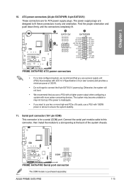
...RXD1 DTR1 DSR1 CTS1 ® COM PIN 1 DCD1 TXD1 GND RTS1# PI1# PRIME X470-PRO Serial port connector The COM module is inadequate. • If you use two or more power-consuming devices. ASUS PRIME X470-PRO 1-15 ATX power connectors (24-pin EATXPWR; 8-pin EATX12V) These connectors are ...Volts GND GND GND GND GND GND GND GND +5 Volts PSON# GND GND +3 Volts -12 Volts +3 Volts +3 Volts PIN 1 ® PRIME X470-PRO ATX power connectors • For a fully configured system, we recommend that complies with 1000W power or above to fit these connectors in only one orientation...
...RXD1 DTR1 DSR1 CTS1 ® COM PIN 1 DCD1 TXD1 GND RTS1# PI1# PRIME X470-PRO Serial port connector The COM module is inadequate. • If you use two or more power-consuming devices. ASUS PRIME X470-PRO 1-15 ATX power connectors (24-pin EATXPWR; 8-pin EATX12V) These connectors are ...Volts GND GND GND GND GND GND GND GND +5 Volts PSON# GND GND +3 Volts -12 Volts +3 Volts +3 Volts PIN 1 ® PRIME X470-PRO ATX power connectors • For a fully configured system, we recommend that complies with 1000W power or above to fit these connectors in only one orientation...
Users Manual English
Page 31
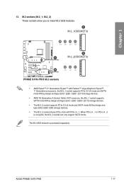
... allow you to install M.2 SSD modules. The M.2 SSD module is occupied, the M.2_2 socket can only support SATA mode. ASUS PRIME X470-PRO 1-17 A M.2_1(SOCKET3) 22110 2280 2260 2242 B A M.2_2(SOCKET3) ® B 2280 2260 2242 PRIME X470-PRO M.2 sockets • AMD Ryzen™ 2nd Generation/ Ryzen™ with Radeon™ Vega Graphics/ Ryzen™ 1st Generation...
... allow you to install M.2 SSD modules. The M.2 SSD module is occupied, the M.2_2 socket can only support SATA mode. ASUS PRIME X470-PRO 1-17 A M.2_1(SOCKET3) 22110 2280 2260 2242 B A M.2_2(SOCKET3) ® B 2280 2260 2242 PRIME X470-PRO M.2 sockets • AMD Ryzen™ 2nd Generation/ Ryzen™ with Radeon™ Vega Graphics/ Ryzen™ 1st Generation...
Users Manual English
Page 33
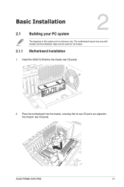
Install the ASUS Q-Shield to the chassis' rear I /O panel. 2. Chapter 2 ASUS PRIME X470-PRO 2-1 Place the motherboard into the chassis, ensuring that its rear I/O ports are aligned to the chassis rear I /O panel. Chapter 2: Basic Installation Basic Installation 2.1 Building your PC system 2 2.1.1 The diagrams in this section are for all models. Motherboard installation 1. The motherboard layout may vary with models, but the installation steps are the same for reference only.
Install the ASUS Q-Shield to the chassis' rear I /O panel. 2. Chapter 2 ASUS PRIME X470-PRO 2-1 Place the motherboard into the chassis, ensuring that its rear I/O ports are aligned to the chassis rear I /O panel. Chapter 2: Basic Installation Basic Installation 2.1 Building your PC system 2 2.1.1 The diagrams in this section are for all models. Motherboard installation 1. The motherboard layout may vary with models, but the installation steps are the same for reference only.
Users Manual English
Page 35
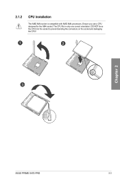
Ensure you use a CPU designed for the AM4 socket. DO NOT force the CPU into the socket to prevent bending the connectors on the socket and damaging the CPU! 1 2 3 Chapter 2 ASUS PRIME X470-PRO 2-3 2.1.2 CPU installation The AMD AM4 socket is compatible with AMD AM4 processors. The CPU fits in only one correct orientation.
Ensure you use a CPU designed for the AM4 socket. DO NOT force the CPU into the socket to prevent bending the connectors on the socket and damaging the CPU! 1 2 3 Chapter 2 ASUS PRIME X470-PRO 2-3 2.1.2 CPU installation The AMD AM4 socket is compatible with AMD AM4 processors. The CPU fits in only one correct orientation.
Users Manual English
Page 37
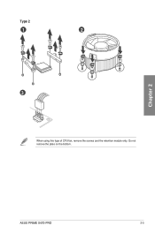
Do not remove the plate on the bottom. Chapter 2 ASUS PRIME X470-PRO 2-5 Type 2 1 2 3 When using this type of CPU fan, remove the screws and the retention module only.
Do not remove the plate on the bottom. Chapter 2 ASUS PRIME X470-PRO 2-5 Type 2 1 2 3 When using this type of CPU fan, remove the screws and the retention module only.
Users Manual English
Page 39
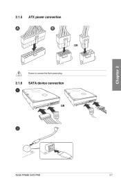
2.1.5 ATX power connection A B OR Ensure to connect the 8-pin power plug. 2.1.6 SATA device connection OR Chapter 2 ASUS PRIME X470-PRO 2-7
2.1.5 ATX power connection A B OR Ensure to connect the 8-pin power plug. 2.1.6 SATA device connection OR Chapter 2 ASUS PRIME X470-PRO 2-7
Users Manual English
Page 41
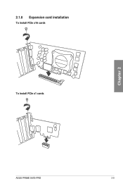
2.1.8 Expansion card installation To install PCIe x16 cards To install PCIe x1 cards Chapter 2 ASUS PRIME X470-PRO 2-9
2.1.8 Expansion card installation To install PCIe x16 cards To install PCIe x1 cards Chapter 2 ASUS PRIME X470-PRO 2-9
Users Manual English
Page 45
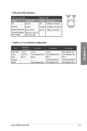
... Out Mic In Center/Sub woofer Rear Speaker Out 8-channel Side Speaker Out Front Speaker Out Mic In Center/Sub woofer Rear Speaker Out Chapter 2 ASUS PRIME X470-PRO 2-13
... Out Mic In Center/Sub woofer Rear Speaker Out 8-channel Side Speaker Out Front Speaker Out Mic In Center/Sub woofer Rear Speaker Out Chapter 2 ASUS PRIME X470-PRO 2-13

Users Manual English
Page 47
Connect to 4-channel Speakers Connect to 6-channel Speakers Chapter 2 Connect to 8-channel Speakers ASUS PRIME X470-PRO 2-15
Connect to 4-channel Speakers Connect to 6-channel Speakers Chapter 2 Connect to 8-channel Speakers ASUS PRIME X470-PRO 2-15

Users Manual English
Page 49
... architecture, offering a user-friendly interface that goes beyond the traditional keyboardonly BIOS controls to "UEFI BIOS" unless otherwise specified. Chapter 3 ASUS PRIME X470-PRO 3-1 Chapter 3: BIOS Setup BIOS Setup 3.1 Knowing BIOS 3 The new ASUS UEFI BIOS is a Unified Extensible Interface that complies with the same smoothness as your operating system. The term "BIOS" in the...
... architecture, offering a user-friendly interface that goes beyond the traditional keyboardonly BIOS controls to "UEFI BIOS" unless otherwise specified. Chapter 3 ASUS PRIME X470-PRO 3-1 Chapter 3: BIOS Setup BIOS Setup 3.1 Knowing BIOS 3 The new ASUS UEFI BIOS is a Unified Extensible Interface that complies with the same smoothness as your operating system. The term "BIOS" in the...

Users Manual English
Page 51
... changed. Refer to find the related item listing Turns the RGB LED lighting or functional LED on the devices you enter the BIOS setup program. ASUS PRIME X470-PRO 3-3 Displays the CPU/motherboard temperature, CPU voltage output, CPU/chassis fan speed, and SATA information Creates storage RAID and configures system overclocking Displays the system...
... changed. Refer to find the related item listing Turns the RGB LED lighting or functional LED on the devices you enter the BIOS setup program. ASUS PRIME X470-PRO 3-3 Displays the CPU/motherboard temperature, CPU voltage output, CPU/chassis fan speed, and SATA information Creates storage RAID and configures system overclocking Displays the system...

Users Manual English
Page 53
... section 3.2.4 EZ Tuning Wizard for that you to MyFavorites menu. Language This button above the menu bar allows you can select for more information. Chapter 3 ASUS PRIME X470-PRO 3-5
... section 3.2.4 EZ Tuning Wizard for that you to MyFavorites menu. Language This button above the menu bar allows you can select for more information. Chapter 3 ASUS PRIME X470-PRO 3-5

Users Manual English
Page 55
Click to select a fan to be configured Click to activate PWM Mode Click to activate DC Mode Select a profile to apply to your fans Click to apply the fan setting Click to undo the changes Click to go back to main menu Select to set a fan profile or manually configure the operating speed of your fans Chapter 3 ASUS PRIME X470-PRO 3-7 3.2.3 Q-Fan Control The QFan Control allows you to manually configure your CPU and chassis fans.
Click to select a fan to be configured Click to activate PWM Mode Click to activate DC Mode Select a profile to apply to your fans Click to apply the fan setting Click to undo the changes Click to go back to main menu Select to set a fan profile or manually configure the operating speed of your fans Chapter 3 ASUS PRIME X470-PRO 3-7 3.2.3 Q-Fan Control The QFan Control allows you to manually configure your CPU and chassis fans.


