User Manual
Page 13
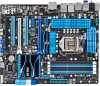
... Check your motherboard package for the following items. User Manual ASUS P8Z68 DELUXE/GEN3 motherboard User guide Support DVD 4 x Serial ATA 6.0 Gb/s cables 2 x Serial ATA 3.0 Gb/s cables 1 x ASUS SLI™ bridge connector 1 x ASUS Q-Shield 1 x ASUS front panel USB 3.0 box 1 x 2-in-1 ASUS Q-Connector kit • If any of ASUS quality motherboards! ASUS P8Z68 DELUXE/GEN3 1-1 The motherboard delivers a host of new features and latest...
... Check your motherboard package for the following items. User Manual ASUS P8Z68 DELUXE/GEN3 motherboard User guide Support DVD 4 x Serial ATA 6.0 Gb/s cables 2 x Serial ATA 3.0 Gb/s cables 1 x ASUS SLI™ bridge connector 1 x ASUS Q-Shield 1 x ASUS front panel USB 3.0 box 1 x 2-in-1 ASUS Q-Connector kit • If any of ASUS quality motherboards! ASUS P8Z68 DELUXE/GEN3 1-1 The motherboard delivers a host of new features and latest...
User Manual
Page 15
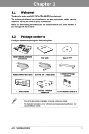
.... Extra SATA 6.0 Gb/s Support The Intel® Z68 Express Chipset natively supports the next-generation Serial ATA (SATA) interface, delivering up to ensure optimized performance. ASUS P8Z68 DELUXE/GEN3 1-3 New generation Dual Intelligent Processors 2 with DIGI+ VRM digital power design launch control into a new era, empowering users with superior flexibility and perfect precision to...
.... Extra SATA 6.0 Gb/s Support The Intel® Z68 Express Chipset natively supports the next-generation Serial ATA (SATA) interface, delivering up to ensure optimized performance. ASUS P8Z68 DELUXE/GEN3 1-3 New generation Dual Intelligent Processors 2 with DIGI+ VRM digital power design launch control into a new era, empowering users with superior flexibility and perfect precision to...
User Manual
Page 17
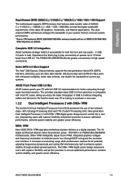
... to different ambient temperatures caused by different climate conditions in different geographic regions and your DIY experience. ASUS Q-Connector ASUS Q-Connector allows you a noiseless PC environment. ASUS P8Z68 DELUXE/GEN3 1-5 Chapter 1 1.3.4 ASUS Quiet Thermal Solution ASUS Fanless Design-Heat-pipe solution The ASUS heat-pipe features 0-dB thermal solution that offers you to easily connect or disconnect the chassis...
... to different ambient temperatures caused by different climate conditions in different geographic regions and your DIY experience. ASUS Q-Connector ASUS Q-Connector allows you a noiseless PC environment. ASUS P8Z68 DELUXE/GEN3 1-5 Chapter 1 1.3.4 ASUS Quiet Thermal Solution ASUS Fanless Design-Heat-pipe solution The ASUS heat-pipe features 0-dB thermal solution that offers you to easily connect or disconnect the chassis...
User Manual
Page 19
... wall socket before touching any component, ensure that the ATX power supply is switched off or the power cord is detached from the power supply. ASUS P8Z68 DELUXE/GEN3 2-1 Failure to do so may cause severe damage to avoid touching the ICs on them due to static electricity. • Hold components by the edges...
... wall socket before touching any component, ensure that the ATX power supply is switched off or the power cord is detached from the power supply. ASUS P8Z68 DELUXE/GEN3 2-1 Failure to do so may cause severe damage to avoid touching the ICs on them due to static electricity. • Hold components by the edges...
User Manual
Page 23
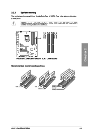
A DDR3 module is notched differently from a DDR or DDR2 module. DO NOT install a DDR or DDR2 memory module to the DDR3 slot. 2.2.3 System memory The motherboard comes with four Double Data Rate 3 (DDR3) Dual Inline Memory Modules (DIMM) slots. Recommended memory configurations Chapter 2 ASUS P8Z68 DELUXE/GEN3 2-5
A DDR3 module is notched differently from a DDR or DDR2 module. DO NOT install a DDR or DDR2 memory module to the DDR3 slot. 2.2.3 System memory The motherboard comes with four Double Data Rate 3 (DDR3) Dual Inline Memory Modules (DIMM) slots. Recommended memory configurations Chapter 2 ASUS P8Z68 DELUXE/GEN3 2-5
User Manual
Page 25
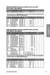
...; • • • • • • • • • • • • • P8Z68 DELUXE/GEN3 Motherboard Qualified Vendors Lists (QVL) DDR3 1866(O.C.) MHz capability Vendor Part No. Timing Apacer 78.AAGD5.9KD(XMP) 6GB(3 x 2GB) DS - ... • • 1.65 • • ASUS P8Z68 DELUXE/GEN3 2-7 Patriot PVT36G2000LLK(XMP) 6GB(3 x 2GB) DS - - G.SKILL F3-15000CL9D-4GBRH (XMP) 4GB(2 x 2GB) DS - OCZ OCZ3P1866C9LV6GK 6GB(3 x 2GB) DS - Chapter 2 P8Z68 DELUXE/GEN3 Motherboard Qualified Vendors Lists (QVL) DDR3 2133(O.C.) MHz ...
...; • • • • • • • • • • • • • P8Z68 DELUXE/GEN3 Motherboard Qualified Vendors Lists (QVL) DDR3 1866(O.C.) MHz capability Vendor Part No. Timing Apacer 78.AAGD5.9KD(XMP) 6GB(3 x 2GB) DS - ... • • 1.65 • • ASUS P8Z68 DELUXE/GEN3 2-7 Patriot PVT36G2000LLK(XMP) 6GB(3 x 2GB) DS - - G.SKILL F3-15000CL9D-4GBRH (XMP) 4GB(2 x 2GB) DS - OCZ OCZ3P1866C9LV6GK 6GB(3 x 2GB) DS - Chapter 2 P8Z68 DELUXE/GEN3 Motherboard Qualified Vendors Lists (QVL) DDR3 2133(O.C.) MHz ...
User Manual
Page 31
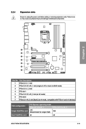
...) VGA configuration Single VGA/PCIe card Dual VGA/PCIe card PCI Express operating mode PCIe 3.0/ 2.0 x16_1 x16 (Recommend for single VGA) x8 PCIe 3.0/ 2.0 x16_2 N/A x8 ASUS P8Z68 DELUXE/GEN3 2-13 2.2.4 Expansion slots Ensure to do so may cause you physical injury and damage motherboard components. Chapter 2 Slot No.
...) VGA configuration Single VGA/PCIe card Dual VGA/PCIe card PCI Express operating mode PCIe 3.0/ 2.0 x16_1 x16 (Recommend for single VGA) x8 PCIe 3.0/ 2.0 x16_2 N/A x8 ASUS P8Z68 DELUXE/GEN3 2-13 2.2.4 Expansion slots Ensure to do so may cause you physical injury and damage motherboard components. Chapter 2 Slot No.
User Manual
Page 33
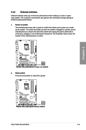
... location of the onboard power-on a bare or opencase system. Reset switch Press the reset switch to fine-tune performance when working on switch. 2. Chapter 2 ASUS P8Z68 DELUXE/GEN3 2-15 2.2.5 Onboard switches Onboard switches allow you to reboot the system. This is ideal for overclockers and gamers who continually change settings to power up...
... location of the onboard power-on a bare or opencase system. Reset switch Press the reset switch to fine-tune performance when working on switch. 2. Chapter 2 ASUS P8Z68 DELUXE/GEN3 2-15 2.2.5 Onboard switches Onboard switches allow you to reboot the system. This is ideal for overclockers and gamers who continually change settings to power up...
User Manual
Page 35
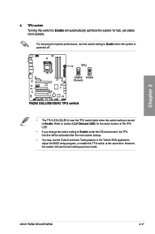
... the BIOS setup program, or enable the TPU switch at the same time. Refer to section 2.2.6 Onboard LEDs for fast, yet stable clock speeds. Chapter 2 4. ASUS P8Z68 DELUXE/GEN3 2-17 TPU switch Turning this switch to Enable.
... the BIOS setup program, or enable the TPU switch at the same time. Refer to section 2.2.6 Onboard LEDs for fast, yet stable clock speeds. Chapter 2 4. ASUS P8Z68 DELUXE/GEN3 2-17 TPU switch Turning this switch to Enable.
User Manual
Page 37
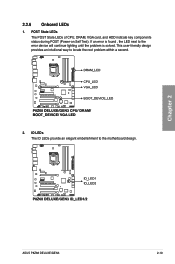
POST State LEDs The POST State LEDs of CPU, DRAM, VGA card, and HDD indicate key components status during POST (Power-on Self Test). Chapter 2 ASUS P8Z68 DELUXE/GEN3 2-19 If an error is found , the LED next to locate the root problem within a second. 2. This user-friendly design provides an intuitional way to the error device will continue lighting until the problem is solved. 2.2.6 Onboard LEDs 1. ID LEDs The ID LEDs provide an elegant embellishment to the motherboard design.
POST State LEDs The POST State LEDs of CPU, DRAM, VGA card, and HDD indicate key components status during POST (Power-on Self Test). Chapter 2 ASUS P8Z68 DELUXE/GEN3 2-19 If an error is found , the LED next to locate the root problem within a second. 2. This user-friendly design provides an intuitional way to the error device will continue lighting until the problem is solved. 2.2.6 Onboard LEDs 1. ID LEDs The ID LEDs provide an elegant embellishment to the motherboard design.
User Manual
Page 39
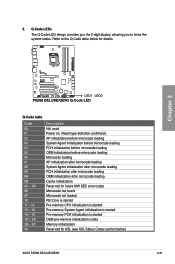
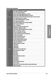
... LEDs The Q-Code LED design provides you the 2-digit display, allowing you to the Q-Code table below for ASL (see ASL Status Codes section below) ASUS P8Z68 DELUXE/GEN3 2-21 Refer to know the system status. AP initialization before microcode loading System Agent initialization before microcode loading PCH initialization before microcode loading OEM initialization...
... LEDs The Q-Code LED design provides you the 2-digit display, allowing you to the Q-Code table below for ASL (see ASL Status Codes section below) ASUS P8Z68 DELUXE/GEN3 2-21 Refer to know the system status. AP initialization before microcode loading System Agent initialization before microcode loading PCH initialization before microcode loading OEM initialization...
User Manual
Page 41
... started SCSI Reset SCSI Detect SCSI Enable Setup Verifying Password Start of Setup Reserved for ASL (see ASL Status Codes section below) Setup Input Wait ASUS P8Z68 DELUXE/GEN3 2-23
... started SCSI Reset SCSI Detect SCSI Enable Setup Verifying Password Start of Setup Reserved for ASL (see ASL Status Codes section below) Setup Input Wait ASUS P8Z68 DELUXE/GEN3 2-23
User Manual
Page 43
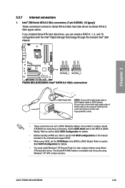
... hard disk drives. If you can create a RAID 0, 1, 5, and 10 configuration with the Intel® Rapid Storage Technology through the onboard Intel® Z68 chipset. ASUS P8Z68 DELUXE/GEN3 2-25 If you installed Serial ATA hard disk drives, you intend to create a Serial ATA RAID set using NCQ, set to Serial ATA 6.0 Gb/s hard...
... hard disk drives. If you can create a RAID 0, 1, 5, and 10 configuration with the Intel® Rapid Storage Technology through the onboard Intel® Z68 chipset. ASUS P8Z68 DELUXE/GEN3 2-25 If you installed Serial ATA hard disk drives, you intend to create a Serial ATA RAID set using NCQ, set to Serial ATA 6.0 Gb/s hard...
User Manual
Page 45
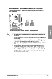
... for data drives only. For 32/64bit Windows XP OS, load first the Marvell shared library driver, and then load Marvell 91xx SATA Controller Driver. ASUS P8Z68 DELUXE/GEN3 2-27 Refer to Serial ATA 6.0 Gb/s hard disk drives via Serial ATA 6.0 Gb/s signal cables. • The SATA6G_E1/E2 (navy blue) connectors are for details...
... for data drives only. For 32/64bit Windows XP OS, load first the Marvell shared library driver, and then load Marvell 91xx SATA Controller Driver. ASUS P8Z68 DELUXE/GEN3 2-27 Refer to Serial ATA 6.0 Gb/s hard disk drives via Serial ATA 6.0 Gb/s signal cables. • The SATA6G_E1/E2 (navy blue) connectors are for details...
User Manual
Page 47
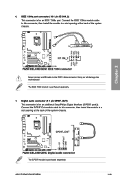
... back of the system chassis. The IEEE 1394 bracket is for an IEEE 1394a port. Digital audio connector (4-1 pin SPDIF_OUT) This connector is purchased separately. 7. ASUS P8Z68 DELUXE/GEN3 2-29 6. The S/PDIF module is for an additional Sony/Philips Digital Interface (S/PDIF) port(s). IEEE 1394a port connector (10-1 pin IE1394_2) This connector is purchased...
... back of the system chassis. The IEEE 1394 bracket is for an IEEE 1394a port. Digital audio connector (4-1 pin SPDIF_OUT) This connector is purchased separately. 7. ASUS P8Z68 DELUXE/GEN3 2-29 6. The S/PDIF module is for an additional Sony/Philips Digital Interface (S/PDIF) port(s). IEEE 1394a port connector (10-1 pin IE1394_2) This connector is purchased...
User Manual
Page 49
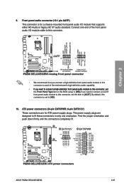
... audio capability. The power supply plugs are for a chassis-mounted front panel audio I /O module cable to fit these connectors in the BIOS setup to [AC97]. ASUS P8Z68 DELUXE/GEN3 2-31 Connect one orientation. Find the proper orientation and push down firmly until the connectors completely fit. By default, this connector to avail of the...
... audio capability. The power supply plugs are for a chassis-mounted front panel audio I /O module cable to fit these connectors in the BIOS setup to [AC97]. ASUS P8Z68 DELUXE/GEN3 2-31 Connect one orientation. Find the proper orientation and push down firmly until the connectors completely fit. By default, this connector to avail of the...
User Manual
Page 51
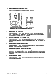
... the system in sleep mode. • Hard disk drive activity LED (2-pin IDE_LED) This 2-pin connector is for the chassis-mounted system warning speaker. 11. ASUS P8Z68 DELUXE/GEN3 2-33
... the system in sleep mode. • Hard disk drive activity LED (2-pin IDE_LED) This 2-pin connector is for the chassis-mounted system warning speaker. 11. ASUS P8Z68 DELUXE/GEN3 2-33
User Manual
Page 53
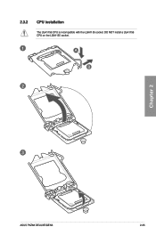
DO NOT install a LGA1156 CPU on the LGA1155 socket. 1 A B 2 3 ASUS P8Z68 DELUXE/GEN3 2-35 Chapter 2 2.3.2 CPU installation The LGA1156 CPU is incompatible with the LGA1155 socket.
DO NOT install a LGA1156 CPU on the LGA1155 socket. 1 A B 2 3 ASUS P8Z68 DELUXE/GEN3 2-35 Chapter 2 2.3.2 CPU installation The LGA1156 CPU is incompatible with the LGA1155 socket.
User Manual
Page 55
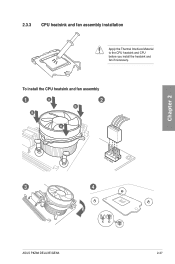
Chapter 2 2.3.3 CPU heatsink and fan assembly installation Apply the Thermal Interface Material to the CPU heatsink and CPU before you install the heatsink and fan if necessary. To install the CPU heatsink and fan assembly 1 A B 2 B A 3 4 ASUS P8Z68 DELUXE/GEN3 2-37
Chapter 2 2.3.3 CPU heatsink and fan assembly installation Apply the Thermal Interface Material to the CPU heatsink and CPU before you install the heatsink and fan if necessary. To install the CPU heatsink and fan assembly 1 A B 2 B A 3 4 ASUS P8Z68 DELUXE/GEN3 2-37
User Manual
Page 57
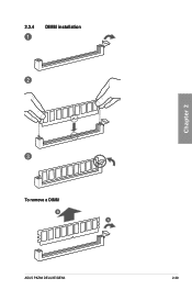
2.3.4 1 DIMM installation 2 Chapter 2 3 To remove a DIMM B A ASUS P8Z68 DELUXE/GEN3 2-39
2.3.4 1 DIMM installation 2 Chapter 2 3 To remove a DIMM B A ASUS P8Z68 DELUXE/GEN3 2-39


