
User Guide
Page 17
.../s signal cables 2 x Serial ATA 3.0 Gb/s power cables 4 x Serial ATA 3.0 Gb/s cables 1 x COM port cable 1 x ASUS Q-Shield (I/O shield) 1 x ASUS 2-in the long line of ASUS quality motherboards! ASUS P8P67 WS Revolution 1-1 Diagnosis Card (Retail version only) 1 x ASUS SLI bridge connector 1 x ASUS 3-Way SLI bridge card ASUS motherboard support DVD User guide If any of new features and latest technologies, making it...
.../s signal cables 2 x Serial ATA 3.0 Gb/s power cables 4 x Serial ATA 3.0 Gb/s cables 1 x COM port cable 1 x ASUS Q-Shield (I/O shield) 1 x ASUS 2-in the long line of ASUS quality motherboards! ASUS P8P67 WS Revolution 1-1 Diagnosis Card (Retail version only) 1 x ASUS SLI bridge connector 1 x ASUS 3-Way SLI bridge card ASUS motherboard support DVD User guide If any of new features and latest technologies, making it...

User Guide
Page 19
... optimized results under a normal OS environment. This also reduces fan noise and extends component longevity! 1.3.2 ASUS Workstation Exclusive Features Platinum Level Power efficiency The P8P67 WS Revolution delivers 92% power efficiency at CPU working loads of a computer cluster that takes up to 4 Tesla...utility. Built-in Dual Intel Server-Class Gigabit LAN For more you use the P8P67 WS Revolution, the more reliable networking, the P8P67 WS Revolution features built-in high-end professional applications or the latest demanding PC game titles. ASUS P8P67 WS Revolution 1-3
... optimized results under a normal OS environment. This also reduces fan noise and extends component longevity! 1.3.2 ASUS Workstation Exclusive Features Platinum Level Power efficiency The P8P67 WS Revolution delivers 92% power efficiency at CPU working loads of a computer cluster that takes up to 4 Tesla...utility. Built-in Dual Intel Server-Class Gigabit LAN For more you use the P8P67 WS Revolution, the more reliable networking, the P8P67 WS Revolution features built-in high-end professional applications or the latest demanding PC game titles. ASUS P8P67 WS Revolution 1-3

User Guide
Page 21
...utilities back and forth. Users can be carried away by different climate conditions in different geographic regions and system loading. ASUS EZ DIY ASUS EZ DIY feature collection provides you easy ways to the heatsink near the back IO ports, where it can easily ...keyboard BIOS input to enable more flexible and convenient mouse controls. ASUS P8P67 WS Revolution 1-5 AI Suite II One-stop Access to Innovative ASUS Features With its fast user-friendly interface, ASUS AI Suite II consolidates all exclusive ASUS features and allows you to supervise overclocking, energy management and fan ...
...utilities back and forth. Users can be carried away by different climate conditions in different geographic regions and system loading. ASUS EZ DIY ASUS EZ DIY feature collection provides you easy ways to the heatsink near the back IO ports, where it can easily ...keyboard BIOS input to enable more flexible and convenient mouse controls. ASUS P8P67 WS Revolution 1-5 AI Suite II One-stop Access to Innovative ASUS Features With its fast user-friendly interface, ASUS AI Suite II consolidates all exclusive ASUS features and allows you to supervise overclocking, energy management and fan ...

User Guide
Page 23
... Absolute Pitch 192khz/24bit audio output, true BD lossless sound, jack-sensing feature, retasking functions and multi-streaming technology. your existing stereo speakers or headphones. ASUS P8P67 WS Revolution 1-7 With these technologies, you may experience a better home-theater audio with loud background sound.
... Absolute Pitch 192khz/24bit audio output, true BD lossless sound, jack-sensing feature, retasking functions and multi-streaming technology. your existing stereo speakers or headphones. ASUS P8P67 WS Revolution 1-7 With these technologies, you may experience a better home-theater audio with loud background sound.
User Guide
Page 26
Chapter summary 2 2.1 Before you proceed 2-1 2.2 Motherboard overview 2-2 2.3 Building your computer system 2-29 2.4 Starting up for the first time 2-45 2.5 Turning off the computer 2-46 ASUS P8P67 WS Revolution
Chapter summary 2 2.1 Before you proceed 2-1 2.2 Motherboard overview 2-2 2.3 Building your computer system 2-29 2.4 Starting up for the first time 2-45 2.5 Turning off the computer 2-46 ASUS P8P67 WS Revolution
User Guide
Page 27
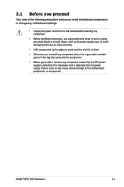
... that came with the component. • Before you install motherboard components or change any motherboard settings. • Unplug the power cord from the power supply. ASUS P8P67 WS Revolution 2-1 Failure to do so may cause severe damage to avoid touching the ICs on them. • Whenever you uninstall any component, place it on a grounded...
... that came with the component. • Before you install motherboard components or change any motherboard settings. • Unplug the power cord from the power supply. ASUS P8P67 WS Revolution 2-1 Failure to do so may cause severe damage to avoid touching the ICs on them. • Whenever you uninstall any component, place it on a grounded...
User Guide
Page 31
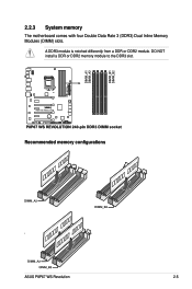
DO NOT install a DDR or DDR2 memory module to the DDR3 slot. Recommended memory configurations ASUS P8P67 WS Revolution 2-5 2.2.3 System memory The motherboard comes with four Double Data Rate 3 (DDR3) Dual Inline Memory Modules (DIMM) slots. A DDR3 module is notched differently from a DDR or DDR2 module.
DO NOT install a DDR or DDR2 memory module to the DDR3 slot. Recommended memory configurations ASUS P8P67 WS Revolution 2-5 2.2.3 System memory The motherboard comes with four Double Data Rate 3 (DDR3) Dual Inline Memory Modules (DIMM) slots. A DDR3 module is notched differently from a DDR or DDR2 module.
User Guide
Page 35
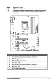
Failure to unplug the power cord before adding or removing expansion cards. Slot Description 1 PCIe 2.0 x16_1 slot (single at x16 or dual at x8/x8 mode) 2 PCIe 2.0 x1_1 slot 3 PCIe 2.0 x16_2 slot (x8 mode) 4 PCIe 2.0 x1_2 slot 5 PCIe 2.0 x16_3 slot (single at x16 or dual at x8/x8 mode) 6 PCIe 2.0 x1_3 slot 7 PCIe 2.0 x16_4 slot (x8 mode) ASUS P8P67 WS Revolution 2-9 2.2.4 Expansion slots Ensure to do so may cause you physical injury and damage motherboard components. 1 2 3 4 5 6 7 Slot No.
Failure to unplug the power cord before adding or removing expansion cards. Slot Description 1 PCIe 2.0 x16_1 slot (single at x16 or dual at x8/x8 mode) 2 PCIe 2.0 x1_1 slot 3 PCIe 2.0 x16_2 slot (x8 mode) 4 PCIe 2.0 x1_2 slot 5 PCIe 2.0 x16_3 slot (single at x16 or dual at x8/x8 mode) 6 PCIe 2.0 x1_3 slot 7 PCIe 2.0 x16_4 slot (x8 mode) ASUS P8P67 WS Revolution 2-9 2.2.4 Expansion slots Ensure to do so may cause you physical injury and damage motherboard components. 1 2 3 4 5 6 7 Slot No.
User Guide
Page 37
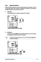
ASUS P8P67 WS Revolution 2-11 EPU switch Turning this switch to enhance system performance. 1. This is powered off. For ensuring the system performance, turn the switch setting to fine-tune performance when working on a bare or open-case system. 2.2.5 Onboard switches Onboard switches allow you to enable or disable the TPU function. 2. TPU switch This switch allows you to Enable when the system is ideal for overclockers and gamers who continually change settings to Enable will automatically detect the current PC loadings and intelligently moderate the power consumption.
ASUS P8P67 WS Revolution 2-11 EPU switch Turning this switch to enhance system performance. 1. This is powered off. For ensuring the system performance, turn the switch setting to fine-tune performance when working on a bare or open-case system. 2.2.5 Onboard switches Onboard switches allow you to enable or disable the TPU function. 2. TPU switch This switch allows you to Enable when the system is ideal for overclockers and gamers who continually change settings to Enable will automatically detect the current PC loadings and intelligently moderate the power consumption.

User Guide
Page 39
ASUS P8P67 WS Revolution 2-13 You may disable the POST State LEDs in sequence during motherboard booting process. TPU LED The TPU LED lights when the TPU switch is solved. 2.2.6 Onboard LEDs 1. This user-friendly design provides an intuitive way to section 3.7.2 Boot Setting Configuration for details. 2. If an error is found, the LED next to the error device will continue lighting until the problem is turned to Enable. POST State LEDs POST State LEDs check key components (CPU, DRAM, VGA card, and HDD) in BIOS. Refer to locate the root problem within seconds.
ASUS P8P67 WS Revolution 2-13 You may disable the POST State LEDs in sequence during motherboard booting process. TPU LED The TPU LED lights when the TPU switch is solved. 2.2.6 Onboard LEDs 1. This user-friendly design provides an intuitive way to section 3.7.2 Boot Setting Configuration for details. 2. If an error is found, the LED next to the error device will continue lighting until the problem is turned to Enable. POST State LEDs POST State LEDs check key components (CPU, DRAM, VGA card, and HDD) in BIOS. Refer to locate the root problem within seconds.
User Guide
Page 41
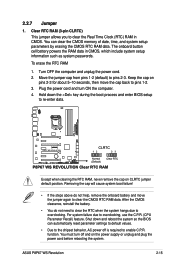
...! • If the steps above do not need to clear the RTC when the system hangs due to overclocking. For system failure due to pins 2-3. ASUS P8P67 WS Revolution 2-15 The onboard button cell battery powers the RAM data in CMOS. Hold down and reboot the system so the BIOS can clear the CMOS...
...! • If the steps above do not need to clear the RTC when the system hangs due to overclocking. For system failure due to pins 2-3. ASUS P8P67 WS Revolution 2-15 The onboard button cell battery powers the RAM data in CMOS. Hold down and reboot the system so the BIOS can clear the CMOS...

User Guide
Page 43
... Configuration for details. • Before creating a RAID set, refer to section 4.4 RAID configurations or the manual bundled in the BIOS to [AHCI Mode] by default. ASUS P8P67 WS Revolution 2-17 If you are set the SATA Mode in the motherboard support DVD. • When using Windows® XP SP3 or later versions. Intel®...
... Configuration for details. • Before creating a RAID set, refer to section 4.4 RAID configurations or the manual bundled in the BIOS to [AHCI Mode] by default. ASUS P8P67 WS Revolution 2-17 If you are set the SATA Mode in the motherboard support DVD. • When using Windows® XP SP3 or later versions. Intel®...

User Guide
Page 45
3. Refer to [AHCI Mode]. ASUS P8P67 WS Revolution 2-19 Marvell® Serial ATA 6.0 Gb/s connectors (7-pin SATA6G_E1/E2 [navy blue]) These connectors connect to Serial ATA 6.0 Gb/s hard disk drives via Serial ATA 6.0 ...
3. Refer to [AHCI Mode]. ASUS P8P67 WS Revolution 2-19 Marvell® Serial ATA 6.0 Gb/s connectors (7-pin SATA6G_E1/E2 [navy blue]) These connectors connect to Serial ATA 6.0 Gb/s hard disk drives via Serial ATA 6.0 ...

User Guide
Page 47
... (4-1 pin SPDIF_OUT) This connector is purchased separately. 6. Connect the S/PDIF Out module cable to this connector, then install the module to the IEEE 1394a connector. ASUS P8P67 WS Revolution 2-21 The IEEE 1394a module is for an IEEE 1394a port.
... (4-1 pin SPDIF_OUT) This connector is purchased separately. 6. Connect the S/PDIF Out module cable to this connector, then install the module to the IEEE 1394a connector. ASUS P8P67 WS Revolution 2-21 The IEEE 1394a module is for an IEEE 1394a port.

User Guide
Page 49
... for a serial (COM) port. By default, this connector, set to [AC97]. The COM module is for a chassis-mounted front panel audio I /O module cable to [HD]; ASUS P8P67 WS Revolution 2-23 8. Front panel audio connector (10-1 pin AAFP) This connector is set the item to [HD]. 9. Connect the serial port module cable to this connector...
... for a serial (COM) port. By default, this connector, set to [AC97]. The COM module is for a chassis-mounted front panel audio I /O module cable to [HD]; ASUS P8P67 WS Revolution 2-23 8. Front panel audio connector (10-1 pin AAFP) This connector is set the item to [HD]. 9. Connect the serial port module cable to this connector...

User Guide
Page 51
... mode OS in APIC mode Leave BIOS and pass control to OS S1 S3 S4 S5 Resume from S1 Resume from S3 Resume from S4 ASUS P8P67 WS Revolution 2-25 Installing G.P. With the LEDs of the diagnosis card facing to avoid electrical shock hazard. 1. Locate the TPM connector (20-1 pin TPM) on the connector...
... mode OS in APIC mode Leave BIOS and pass control to OS S1 S3 S4 S5 Resume from S1 Resume from S3 Resume from S4 ASUS P8P67 WS Revolution 2-25 Installing G.P. With the LEDs of the diagnosis card facing to avoid electrical shock hazard. 1. Locate the TPM connector (20-1 pin TPM) on the connector...

User Guide
Page 53
... reset button for the system power LED. Connect the HDD Activity LED cable to this connector. The speaker allows you turn on the BIOS settings. ASUS P8P67 WS Revolution 2-27 Connect the chassis power LED cable to this connector.
... reset button for the system power LED. Connect the HDD Activity LED cable to this connector. The speaker allows you turn on the BIOS settings. ASUS P8P67 WS Revolution 2-27 Connect the chassis power LED cable to this connector.

User Guide
Page 57
2.3.3 CPU heatsink and fan assembly installation Apply the Thermal Interface Material to the CPU heatsink and CPU before you install the heatsink and fan if necessary. To install the CPU heatsink and fan assembly 1 A 2 B B A 3 4 ASUS P8P67 WS Revolution 2-31
2.3.3 CPU heatsink and fan assembly installation Apply the Thermal Interface Material to the CPU heatsink and CPU before you install the heatsink and fan if necessary. To install the CPU heatsink and fan assembly 1 A 2 B B A 3 4 ASUS P8P67 WS Revolution 2-31

User Guide
Page 59
2.3.4 1 DIMM installation 2 3 To remove a DIMM B A ASUS P8P67 WS Revolution 2-33
2.3.4 1 DIMM installation 2 3 To remove a DIMM B A ASUS P8P67 WS Revolution 2-33

User Guide
Page 61
3 DO NOT overtighten the screws! Doing so can damage the motherboard. ASUS P8P67 WS Revolution 2-35
3 DO NOT overtighten the screws! Doing so can damage the motherboard. ASUS P8P67 WS Revolution 2-35


