
User Manual
Page 13
... package for the following items. User Manual ASUS P8H77-M PRO motherboard User manual Support DVD 2 x Serial ATA 6.0 Gb/s cables 2 x Serial ATA 3.0 Gb/s cables 1 x ASUS Q-Shield 1 x 2-in your package with the list below. 1.2 Package contents Check your retailer. • The illustrations above are for buying an ASUS® P8H77-M PRO motherboard! ASUS P8H77-M PRO 1-1 Before you for reference only. Thank you...
... package for the following items. User Manual ASUS P8H77-M PRO motherboard User manual Support DVD 2 x Serial ATA 6.0 Gb/s cables 2 x Serial ATA 3.0 Gb/s cables 1 x ASUS Q-Shield 1 x 2-in your package with the list below. 1.2 Package contents Check your retailer. • The illustrations above are for buying an ASUS® P8H77-M PRO motherboard! ASUS P8H77-M PRO 1-1 Before you for reference only. Thank you...
User Manual
Page 15
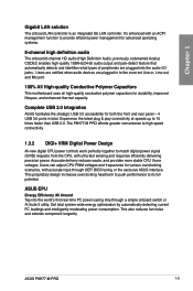
...world's first real-time PC power saving chip through UEFI BIOS tuning or the exclusive ASUS interface. ASUS EPU Energy Efficiency All Around Tap into the audio I/O jacks. ASUS P8H77-M PRO 1-3 It's enhanced with an ACPI management function to match digital power signal (SVID)... requests from the CPU, with accurate input through a simple onboard switch or AI Suite II utility. The P8H77-M PRO affords greater convenience to high speed...
...world's first real-time PC power saving chip through UEFI BIOS tuning or the exclusive ASUS interface. ASUS EPU Energy Efficiency All Around Tap into the audio I/O jacks. ASUS P8H77-M PRO 1-3 It's enhanced with an ACPI management function to match digital power signal (SVID)... requests from the CPU, with accurate input through a simple onboard switch or AI Suite II utility. The P8H77-M PRO affords greater convenience to high speed...
User Manual
Page 17
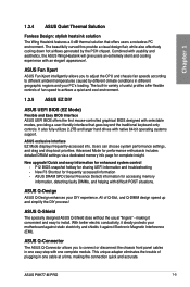
... BIOS snapshot hotkey for complete insight. ASUS Q-Design ASUS Q-Design enhances your motherboard against static electricity and shields it convenient and easy to different ambient temperatures caused by the PCH chipset. ASUS P8H77-M PRO 1-5 ASUS exclusive interface EZ Mode displays frequently-accessed... info. It also fully-utilizes 2.2TB and larger hard drives with difficult POST situations. ASUS DRAM SPD (Serial Presence Detect) information for...
... BIOS snapshot hotkey for complete insight. ASUS Q-Design ASUS Q-Design enhances your motherboard against static electricity and shields it convenient and easy to different ambient temperatures caused by the PCH chipset. ASUS P8H77-M PRO 1-5 ASUS exclusive interface EZ Mode displays frequently-accessed... info. It also fully-utilizes 2.2TB and larger hard drives with difficult POST situations. ASUS DRAM SPD (Serial Presence Detect) information for...

User Manual
Page 19
ASUS P8H77-M PRO 2-1 Failure to do so may cause severe damage to avoid touching the ICs on them. • Whenever you uninstall any component, place it on a grounded ...
ASUS P8H77-M PRO 2-1 Failure to do so may cause severe damage to avoid touching the ICs on them. • Whenever you uninstall any component, place it on a grounded ...

User Manual
Page 23
ASUS P8H77-M PRO 2-5 DIMM_A1 DIMM_A2 DIMM_B1 DIMM_B2 Chapter 2 2.2.3 System memory The motherboard comes with four Double Data Rate 3 (DDR3) Dual Inline Memory Modules (DIMM) slots. P8H77-M PRO P8H77-M PRO 240-pin DDR3 DIMM sockets Recommended memory configurations We recommend that you install the memory modules from a DDR or DDR2 module. DO NOT install a DDR or DDR2 memory module to the DDR3 slot. A DDR3 module is notched differently from the blue slots for better overclocking capability.
ASUS P8H77-M PRO 2-5 DIMM_A1 DIMM_A2 DIMM_B1 DIMM_B2 Chapter 2 2.2.3 System memory The motherboard comes with four Double Data Rate 3 (DDR3) Dual Inline Memory Modules (DIMM) slots. P8H77-M PRO P8H77-M PRO 240-pin DDR3 DIMM sockets Recommended memory configurations We recommend that you install the memory modules from a DDR or DDR2 module. DO NOT install a DDR or DDR2 memory module to the DDR3 slot. A DDR3 module is notched differently from the blue slots for better overclocking capability.

User Manual
Page 29
Timing - H5TQ2G83AFR - 1.5V • • • - • • • ASUS P8H77-M PRO 2-11 Size SS/ Chip Brand DS EBJ10UE8EDF0-DJ-F 1GB SS ELPIDA EBJ21UE8EDF0-DJ-F 2GB DS ELPIDA...• • - 9 XMP 1.25V • • • J2108BCSE-DJ-F 9 1.5V • • • J2108BCSE-DJ-F - 1.5V • • • D2568JENCNGD9U - Chapter 2 P8H77-M PRO Motherboard Qualified Vendors Lists (QVL) DDR3 1333 MHz capability (continued) Vendors ELPIDA ELPIDA G.SKILL G.SKILL G.SKILL G.SKILL G.SKILL G.SKILL GEIL GEIL GEIL GEIL Hynix Hynix...
Timing - H5TQ2G83AFR - 1.5V • • • - • • • ASUS P8H77-M PRO 2-11 Size SS/ Chip Brand DS EBJ10UE8EDF0-DJ-F 1GB SS ELPIDA EBJ21UE8EDF0-DJ-F 2GB DS ELPIDA...• • - 9 XMP 1.25V • • • J2108BCSE-DJ-F 9 1.5V • • • J2108BCSE-DJ-F - 1.5V • • • D2568JENCNGD9U - Chapter 2 P8H77-M PRO Motherboard Qualified Vendors Lists (QVL) DDR3 1333 MHz capability (continued) Vendors ELPIDA ELPIDA G.SKILL G.SKILL G.SKILL G.SKILL G.SKILL G.SKILL GEIL GEIL GEIL GEIL Hynix Hynix...

User Manual
Page 31
... support is subject to the CPU behavior, DDR3 2133/1866MHz memory module will run at DDR3 2000/1800MHz frequency as Single-channel memory configuration. or D.O.C.P. ASUS P8H77-M PRO 2-13 Side(s): SS - DS Brand Timing Voltage DIMM socket support (Optional) 1 DIMM 2 DIMMs 4 DIMMs Crucial CT12864BA1067.8FF 1GB SS Micron 9GF22D9KPT 7 - • • • Crucial...
... support is subject to the CPU behavior, DDR3 2133/1866MHz memory module will run at DDR3 2000/1800MHz frequency as Single-channel memory configuration. or D.O.C.P. ASUS P8H77-M PRO 2-13 Side(s): SS - DS Brand Timing Voltage DIMM socket support (Optional) 1 DIMM 2 DIMMs 4 DIMMs Crucial CT12864BA1067.8FF 1GB SS Micron 9GF22D9KPT 7 - • • • Crucial...

User Manual
Page 33
... 9172 PCIE x16_1 PCIE x16_2 PCIE x1_1 PCIE x1_2 Intel PCH SATA Controller HD Audio USB 2.0_1 USB 2.0_2 USB 3.0 A B C D E shared - - - - - - shared - - - - - - F G H - - - - - - - - - - - - - - - - - - - - - - shared - - - shared - - - Chapter 2 ASUS P8H77-M PRO 2-15 shared - - - - shared - - - - shared - - - - - - - - - - - - - - - - shared - - - - shared - - IRQ assignments for better thermal environment. shared - - shared - - - - - See page 2-24 for details.
... 9172 PCIE x16_1 PCIE x16_2 PCIE x1_1 PCIE x1_2 Intel PCH SATA Controller HD Audio USB 2.0_1 USB 2.0_2 USB 3.0 A B C D E shared - - - - - - shared - - - - - - F G H - - - - - - - - - - - - - - - - - - - - - - shared - - - shared - - - Chapter 2 ASUS P8H77-M PRO 2-15 shared - - - - shared - - - - shared - - - - - - - - - - - - - - - - shared - - - - shared - - IRQ assignments for better thermal environment. shared - - shared - - - - - See page 2-24 for details.

User Manual
Page 35
... Installing DIMMs that you download and update to the latest BIOS version from the ASUS website at www.asus.com. • If you to fine-tune performance when working on the ASUS website at www.asus.com after the whole tuning process, the DRAM_LED remains lit. function. •...process, the system continues memory tuning after turning on the computer. switch until the DRAM_LED starts blinking to boot after using the MemOK! ASUS P8H77-M PRO 2-17 switch does not function under the Windows™ OS environment. • During the tuning process, the system loads and tests ...
... Installing DIMMs that you download and update to the latest BIOS version from the ASUS website at www.asus.com. • If you to fine-tune performance when working on the ASUS website at www.asus.com after the whole tuning process, the DRAM_LED remains lit. function. •...process, the system continues memory tuning after turning on the computer. switch until the DRAM_LED starts blinking to boot after using the MemOK! ASUS P8H77-M PRO 2-17 switch does not function under the Windows™ OS environment. • During the tuning process, the system loads and tests ...

User Manual
Page 37
... OFF Standby Power Powered Off P8H77-M PRO Onboard LED 2. If an error is found, the LED next to the error device will remain lit until the problem is changed to Enable. EPU ... the power cable before removing or plugging in any motherboard component. This is ON, in sleep mode, or in sequence during the motherboard boot process. P8H77-M PRO EPU_LED P8H77-M PRO EPU LED ASUS P8H77-M PRO 2-19 Chapter 2 2.2.7 Onboard LEDs 1. The illustration below shows the location of the onboard LED. DRAM LED...
... OFF Standby Power Powered Off P8H77-M PRO Onboard LED 2. If an error is found, the LED next to the error device will remain lit until the problem is changed to Enable. EPU ... the power cable before removing or plugging in any motherboard component. This is ON, in sleep mode, or in sequence during the motherboard boot process. P8H77-M PRO EPU_LED P8H77-M PRO EPU LED ASUS P8H77-M PRO 2-19 Chapter 2 2.2.7 Onboard LEDs 1. The illustration below shows the location of the onboard LED. DRAM LED...

User Manual
Page 39
... RSATA_RXP1 RSATA_RXN1 GND RSATA_TXN1 RSATA_TXP1 GND Chapter 2 • These connectors are using these connectors, set the SATA Mode item in the BIOS to [RAID Mode]. ASUS P8H77-M PRO 2-21 Refer to Serial ATA 6.0 Gb/s hard disk drives via Serial ATA 6.0 Gb/s signal cables. The Serial ATA RAID feature is available only if you...
... RSATA_RXP1 RSATA_RXN1 GND RSATA_TXN1 RSATA_TXP1 GND Chapter 2 • These connectors are using these connectors, set the SATA Mode item in the BIOS to [RAID Mode]. ASUS P8H77-M PRO 2-21 Refer to Serial ATA 6.0 Gb/s hard disk drives via Serial ATA 6.0 Gb/s signal cables. The Serial ATA RAID feature is available only if you...

User Manual
Page 41
.../s hard disk drives via Serial ATA 6.0 Gb/s signal cables. Chapter 2 ASUS P8H77-M PRO 2-23 Marvell® Serial ATA 6.0Gb/s connectors (7-pin SATA6G_E1 [navy blue]) This connector connects to section 3.5.6 Onboard Devices Configuration for data drives only. P8H77-M PRO SATA6G_E1 GND RSATA_TXP1 RSATA_TXN1 GND RSATA_RXP1 RSATA_RXN1 GND P8H77-M PRO Marvell® SATA 6.0 Gb/s connectors • The SATA6G_E1 (navy...
.../s hard disk drives via Serial ATA 6.0 Gb/s signal cables. Chapter 2 ASUS P8H77-M PRO 2-23 Marvell® Serial ATA 6.0Gb/s connectors (7-pin SATA6G_E1 [navy blue]) This connector connects to section 3.5.6 Onboard Devices Configuration for data drives only. P8H77-M PRO SATA6G_E1 GND RSATA_TXP1 RSATA_TXN1 GND RSATA_RXP1 RSATA_RXN1 GND P8H77-M PRO Marvell® SATA 6.0 Gb/s connectors • The SATA6G_E1 (navy...

User Manual
Page 43
...We recommend that you want to connect an AC'97 front panel audio module to this connector, then install the module to [AC97]. ASUS P8H77-M PRO 2-25 Digital audio connector (4-1 pin SPDIF_OUT) This connector is set the item to a slot opening at the back of the system chassis.... +5V SPDIFOUT GND Chapter 2 P8H77-M PRO SPDIF_OUT P8H77-M PRO Digital audio connector The S/PDIF module is for an additional Sony/Philips Digital Interface (S/PDIF) port(s). Connect the S/PDIF Out module ...
...We recommend that you want to connect an AC'97 front panel audio module to this connector, then install the module to [AC97]. ASUS P8H77-M PRO 2-25 Digital audio connector (4-1 pin SPDIF_OUT) This connector is set the item to a slot opening at the back of the system chassis.... +5V SPDIFOUT GND Chapter 2 P8H77-M PRO SPDIF_OUT P8H77-M PRO Digital audio connector The S/PDIF module is for an additional Sony/Philips Digital Interface (S/PDIF) port(s). Connect the S/PDIF Out module ...

User Manual
Page 45
...a fully configured system, we recommend that complies with ATX 12 V Specification 2.0 (or later version) and provides a minimum power of the system chassis. ASUS P8H77-M PRO 2-27 Connect the serial port module cable to the connector, then install the module to a slot opening at http://support....asus. The power supply plugs are for a serial (COM) port. Find the proper orientation and push down firmly until the connectors completely fit. COM1 PIN 1 RXD DTR DSR CTS DCD TXD GND RTS RI Chapter 2 P8H77-M PRO P8H77-M PRO Serial port (COM1) connector 11....
...a fully configured system, we recommend that complies with ATX 12 V Specification 2.0 (or later version) and provides a minimum power of the system chassis. ASUS P8H77-M PRO 2-27 Connect the serial port module cable to the connector, then install the module to a slot opening at http://support....asus. The power supply plugs are for a serial (COM) port. Find the proper orientation and push down firmly until the connectors completely fit. COM1 PIN 1 RXD DTR DSR CTS DCD TXD GND RTS RI Chapter 2 P8H77-M PRO P8H77-M PRO Serial port (COM1) connector 11....
User Manual
Page 47
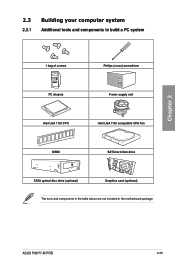
ASUS P8H77-M PRO 2-29 Chapter 2 2.3 Building your computer system 2.3.1 Additional tools and components to build a PC system 1 bag of screws Philips (cross) screwdriver PC chassis Power supply unit Intel LGA 1155 CPU Intel LGA 1155 compatible CPU Fan DIMM SATA hard disk drive SATA optical disc drive (optional) Graphics card (optional) The tools and components in the table above are not included in the motherboard package.
ASUS P8H77-M PRO 2-29 Chapter 2 2.3 Building your computer system 2.3.1 Additional tools and components to build a PC system 1 bag of screws Philips (cross) screwdriver PC chassis Power supply unit Intel LGA 1155 CPU Intel LGA 1155 compatible CPU Fan DIMM SATA hard disk drive SATA optical disc drive (optional) Graphics card (optional) The tools and components in the table above are not included in the motherboard package.

User Manual
Page 51
To uninstall the CPU heatsink and fan assembly 1 2 B A B A Chapter 2 ASUS P8H77-M PRO 2-33
To uninstall the CPU heatsink and fan assembly 1 2 B A B A Chapter 2 ASUS P8H77-M PRO 2-33

User Manual
Page 53
2.3.5 1 Motherboard installation The diagrams in this section are for reference only. The motherboard layout may vary between models, but the installation steps remain the same. 2 Chapter 2 ASUS P8H77-M PRO 2-35
2.3.5 1 Motherboard installation The diagrams in this section are for reference only. The motherboard layout may vary between models, but the installation steps remain the same. 2 Chapter 2 ASUS P8H77-M PRO 2-35

User Manual
Page 57
2.3.8 Front I/O Connector To install ASUS Q-Connector 1 2 IDE_LED+ IDE_LED- IDE_LED PWR Ground Reset Ground POWER SW RESET SW To install USB 2.0 Connector To install front panel audio connector Chapter 2 USB 2.0 To install USB 3.0 Connector USB 3.0 ASUS P8H77-M PRO AAFP 2-39
2.3.8 Front I/O Connector To install ASUS Q-Connector 1 2 IDE_LED+ IDE_LED- IDE_LED PWR Ground Reset Ground POWER SW RESET SW To install USB 2.0 Connector To install front panel audio connector Chapter 2 USB 2.0 To install USB 3.0 Connector USB 3.0 ASUS P8H77-M PRO AAFP 2-39
User Manual
Page 59
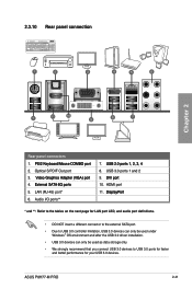
...** 7. ��U��S�B��2�.�0��p�o�r�ts��1�,�2��, �3�,�4� 8. ASUS P8H77-M PRO 2-41 2.3.10 Rear panel connection Chapter 2 Rear panel connectors 1. ��P�S�/2��K�e�y�b�o�a�r�d�/M��...
...** 7. ��U��S�B��2�.�0��p�o�r�ts��1�,�2��, �3�,�4� 8. ASUS P8H77-M PRO 2-41 2.3.10 Rear panel connection Chapter 2 Rear panel connectors 1. ��P�S�/2��K�e�y�b�o�a�r�d�/M��...

User Manual
Page 61
Chapter 2 2.3.11 Audio I/O connections Audio I/O ports Connect to Headphone and Mic Connect to Stereo Speakers Connect to 2.1 channel Speakers ASUS P8H77-M PRO 2-43
Chapter 2 2.3.11 Audio I/O connections Audio I/O ports Connect to Headphone and Mic Connect to Stereo Speakers Connect to 2.1 channel Speakers ASUS P8H77-M PRO 2-43


