
User Manual
Page 1
P8H67 Motherboard
P8H67 Motherboard
User Manual
Page 3
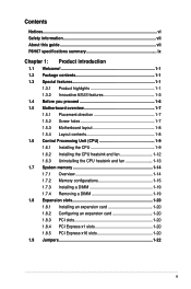
Contents Notices...vi Safety information vii About this guide vii P8H67 specifications summary ix Chapter 1: Product introduction 1.1 Welcome 1-1 1.2 Package contents 1-1 1.3 Special features 1-1 1.3.1 Product highlights 1-1 1.3.2 Innovative ASUS features 1-3 1.4 Before you proceed 1-6 1.5 Motherboard overview 1-7 1.5.1 Placement direction 1-7 1.5.2 Screw holes 1-7 1.5.3 Motherboard layout 1-8 1.5.4 Layout contents 1-8 1.6 Central Processing Unit (CPU 1-9 1.6.1 Installing the CPU 1-9 1.6.2 Installing the CPU heatsink and fan 1-12 1.6.3 Uninstalling...
Contents Notices...vi Safety information vii About this guide vii P8H67 specifications summary ix Chapter 1: Product introduction 1.1 Welcome 1-1 1.2 Package contents 1-1 1.3 Special features 1-1 1.3.1 Product highlights 1-1 1.3.2 Innovative ASUS features 1-3 1.4 Before you proceed 1-6 1.5 Motherboard overview 1-7 1.5.1 Placement direction 1-7 1.5.2 Screw holes 1-7 1.5.3 Motherboard layout 1-8 1.5.4 Layout contents 1-8 1.6 Central Processing Unit (CPU 1-9 1.6.1 Installing the CPU 1-9 1.6.2 Installing the CPU heatsink and fan 1-12 1.6.3 Uninstalling...
User Manual
Page 6
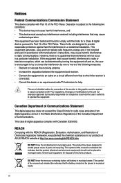
..., and Restriction of the monitor to the graphics card is encouraged to try to Part 15 of Communications. DO NOT throw the motherboard in municipal waste. This product has been designed to which can radiate radio frequency energy and, if not installed and used in ...with manufacturer's instructions, may cause undesired operation. This equipment generates, uses and can be placed in our products at ASUS REACH website at http://csr.asus.com/english/REACH.htm. This symbol of electronic products. Operation is no guarantee that to enable proper reuse of the...
..., and Restriction of the monitor to the graphics card is encouraged to try to Part 15 of Communications. DO NOT throw the motherboard in municipal waste. This product has been designed to which can radiate radio frequency energy and, if not installed and used in ...with manufacturer's instructions, may cause undesired operation. This equipment generates, uses and can be placed in our products at ASUS REACH website at http://csr.asus.com/english/REACH.htm. This symbol of electronic products. Operation is no guarantee that to enable proper reuse of the...
User Manual
Page 7
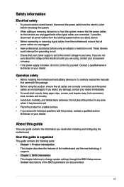
...all power cables are unplugged. • Seek professional assistance before using , contact your retailer. If you need when installing and configuring the motherboard. About this guide is broken, do not try to fix it supports. • Chapter 2: BIOS information This chapter tells how to...disconnect the power cable from the electric outlet before relocating the system. • When adding or removing devices to or from the motherboard, ensure that all cables are correctly connected and the power cables are not damaged. Contact a qualified service technician or your local power...
...all power cables are unplugged. • Seek professional assistance before using , contact your retailer. If you need when installing and configuring the motherboard. About this guide is broken, do not try to fix it supports. • Chapter 2: BIOS information This chapter tells how to...disconnect the power cable from the electric outlet before relocating the system. • When adding or removing devices to or from the motherboard, ensure that all cables are correctly connected and the power cables are not damaged. Contact a qualified service technician or your local power...
User Manual
Page 13
... Product highlights LGA1155 socket for buying an ASUS® P8H67 motherboard! Thank you start installing the motherboard, and hardware devices on it another standout in the long line of the above items is damaged or missing, contact your motherboard package for the following items. Motherboard Cables Accessories Application DVD Documentation ASUS P8H67 motherboard 2 x Serial ATA 6.0Gb/s cables 1 x Ultra DMA...
... Product highlights LGA1155 socket for buying an ASUS® P8H67 motherboard! Thank you start installing the motherboard, and hardware devices on it another standout in the long line of the above items is damaged or missing, contact your motherboard package for the following items. Motherboard Cables Accessories Application DVD Documentation ASUS P8H67 motherboard 2 x Serial ATA 6.0Gb/s cables 1 x Ultra DMA...
User Manual
Page 14
...utilizing serial point-to 6.0 Gb/s data transfer. USB 3.0 support Experience ultra-fast data transfer at the back I /O This motherboard provides convenient connectivity to external home theater audio systems via the optical S/PDIF (SONY-PHILIPS Digital Interface) out connecor at 4.8Gbps... with USB 3.0 - the latest connectivity standard. PCI Express 2.0 support This motherboard supports PCI Express 2.0 devices for advanced operating systems. 1-2 Chapter 1: Product introduction The S/PDIF transfers digital audio without converting it...
...utilizing serial point-to 6.0 Gb/s data transfer. USB 3.0 support Experience ultra-fast data transfer at the back I /O This motherboard provides convenient connectivity to external home theater audio systems via the optical S/PDIF (SONY-PHILIPS Digital Interface) out connecor at 4.8Gbps... with USB 3.0 - the latest connectivity standard. PCI Express 2.0 support This motherboard supports PCI Express 2.0 devices for advanced operating systems. 1-2 Chapter 1: Product introduction The S/PDIF transfers digital audio without converting it...
User Manual
Page 15
...motherboard from damage caused by power surges from switching power supply (PSU). This allows you to patch memory issues. This easy OC tool allows you to achieve a total system level up and running in multiple-GPU configurations of CrossFireX™. quickly ensures memory boot compatibility. Get your system boot success. ASUS P8H67... 1-3 Moreover, the ASUS OC profiles in different scenarios. Innovative ASUS features ASUS EFI BIOS (EZ Mode) ASUS brand new EFI BIOS offers a user-friendly interface...
...motherboard from damage caused by power surges from switching power supply (PSU). This allows you to patch memory issues. This easy OC tool allows you to achieve a total system level up and running in multiple-GPU configurations of CrossFireX™. quickly ensures memory boot compatibility. Get your system boot success. ASUS P8H67... 1-3 Moreover, the ASUS OC profiles in different scenarios. Innovative ASUS features ASUS EFI BIOS (EZ Mode) ASUS brand new EFI BIOS offers a user-friendly interface...
User Manual
Page 16
... a corrupted BIOS file using an OS-based utility. 1-4 Chapter 1: Product introduction AI Suite II With its user-friendly interface, ASUS AI Suite II consolidates ASUS features into a 256-color boot logo for motherboard users, but also effectively cools down hot airflows generated by different climate conditions in different geographic regions and your favorite...
... a corrupted BIOS file using an OS-based utility. 1-4 Chapter 1: Product introduction AI Suite II With its user-friendly interface, ASUS AI Suite II consolidates ASUS features into a 256-color boot logo for motherboard users, but also effectively cools down hot airflows generated by different climate conditions in different geographic regions and your favorite...
User Manual
Page 17
...ASUS P8H67 1-5 Simply shut down and reboot the system, and the BIOS automatically restores the CPU parameters to open the system chassis and clear the RTC data. feature automatically restores the CPU default settings when the system hangs due to energy consumptions. ErP ready The motherboard... is in regards to overclocking failure. C.P.R. This is European Union´s Energy-related Products (ErP) ready, and ErP requires products to meet certain energy efficiency requirements in line with ASUS vision of creating environment-friendly and...
...ASUS P8H67 1-5 Simply shut down and reboot the system, and the BIOS automatically restores the CPU parameters to open the system chassis and clear the RTC data. feature automatically restores the CPU default settings when the system hangs due to energy consumptions. ErP ready The motherboard... is in regards to overclocking failure. C.P.R. This is European Union´s Energy-related Products (ErP) ready, and ErP requires products to meet certain energy efficiency requirements in line with ASUS vision of creating environment-friendly and...
User Manual
Page 18
..., place it on a grounded antistatic pad or in the bag that came with the component. • Before you install motherboard components or change any motherboard settings. • Unplug the power cord from the wall socket before touching any component. • Before handling components, use..., such as the power supply case, to avoid damaging them due to static electricity. • Hold components by the edges to the motherboard, peripherals, or components. 1-6 Chapter 1: Product introduction 1.4 Before you proceed Take note of the following precautions before you install or remove any...
..., place it on a grounded antistatic pad or in the bag that came with the component. • Before you install motherboard components or change any motherboard settings. • Unplug the power cord from the wall socket before touching any component. • Before handling components, use..., such as the power supply case, to avoid damaging them due to static electricity. • Hold components by the edges to the motherboard, peripherals, or components. 1-6 Chapter 1: Product introduction 1.4 Before you proceed Take note of the following precautions before you install or remove any...
User Manual
Page 19
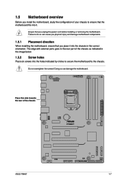
... of the chassis P8H67 ASUS P8H67 1-7 The edge with external ports goes to the rear part of the chassis as indicated in the correct orientation. 1.5 Motherboard overview Before you install the motherboard, study the configuration of your chassis to ensure that the motherboard fits into it...Place six screws into the holes indicated by circles to secure the motherboard to the chassis. Doing so can cause you physical injury and damage motherboard components. 1.5.1 Placement direction When installing the motherboard, ensure that you unplug the power cord before installing or removing ...
... of the chassis P8H67 ASUS P8H67 1-7 The edge with external ports goes to the rear part of the chassis as indicated in the correct orientation. 1.5 Motherboard overview Before you install the motherboard, study the configuration of your chassis to ensure that the motherboard fits into it...Place six screws into the holes indicated by circles to secure the motherboard to the chassis. Doing so can cause you physical injury and damage motherboard components. 1.5.1 Placement direction When installing the motherboard, ensure that you unplug the power cord before installing or removing ...
User Manual
Page 21
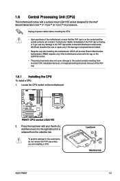
...or misplacement/loss/incorrect removal of the motherboard, ensure that the PnP cap is on the socket and the socket contacts are installing a CPU. P8H67 P8H67 CPU socket LGA1155 2. To prevent damage to the socket contacts resulting from the retention tab. ASUS will shoulder the cost of repair only... for the Intel® Second Generation Core™ i7 / Core™ i5 / Core™ i3 processors. Load lever A B Retention tab ASUS P8H67 1-9 1.6 Central Processing Unit (CPU) The motherboard comes with your retailer immediately if the PnP cap is missing, or if you are not bent...
...or misplacement/loss/incorrect removal of the motherboard, ensure that the PnP cap is on the socket and the socket contacts are installing a CPU. P8H67 P8H67 CPU socket LGA1155 2. To prevent damage to the socket contacts resulting from the retention tab. ASUS will shoulder the cost of repair only... for the Intel® Second Generation Core™ i7 / Core™ i5 / Core™ i3 processors. Load lever A B Retention tab ASUS P8H67 1-9 1.6 Central Processing Unit (CPU) The motherboard comes with your retailer immediately if the PnP cap is missing, or if you are not bent...

User Manual
Page 24
... buy a CPU separately, ensure that you have properly applied Thermal Interface Material to the CPU fan connector. 2. Place the heatsink on the motherboard. Ensure that you install the heatsink and fan assembly. B B Orient the heatsink and fan assembly A such that you have installed the... motherboard to the chassis before you use only Intel®‑certified multi‑directional heatsink and fan. • Your Intel® LGA1155 ...
... buy a CPU separately, ensure that you have properly applied Thermal Interface Material to the CPU fan connector. 2. Place the heatsink on the motherboard. Ensure that you install the heatsink and fan assembly. B B Orient the heatsink and fan assembly A such that you have installed the... motherboard to the chassis before you use only Intel®‑certified multi‑directional heatsink and fan. • Your Intel® LGA1155 ...
User Manual
Page 25
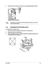
Disconnect the CPU fan cable from the motherboard. Rotate each fastener counterclockwise. 3. A B A B B A B A ASUS P8H67 1-13 Connect the CPU fan cable to disengage the heatsink and fan assembly from the connector on the motherboard labeled CPU_FAN. CPU_FAN CPU FAN PWM CPU FAN IN CPU FAN PWR GND P8H67 P8H67 CPU fan connector Do not forget to plug this...
Disconnect the CPU fan cable from the motherboard. Rotate each fastener counterclockwise. 3. A B A B B A B A ASUS P8H67 1-13 Connect the CPU fan cable to disengage the heatsink and fan assembly from the connector on the motherboard labeled CPU_FAN. CPU_FAN CPU FAN PWM CPU FAN IN CPU FAN PWR GND P8H67 P8H67 CPU fan connector Do not forget to plug this...
User Manual
Page 26
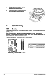
... has the same physical dimensions as a DDR2 DIMM but is notched differently to ensure correct orientation when reinstalling. 1.7 System memory 1.7.1 Overview The motherboard comes with less power consumption. DDR3 modules are developed for better performance with four Double Data Rate 3 (DDR3) Dual Inline Memory Modules (DIMM.... 4. The figure illustrates the location of the DDR3 DIMM sockets: DIMM_A1 DIMM_A2 DIMM_B1 DIMM_B2 Channel Sockets Channel A DIMM_A1 and DIMM_A2 P8H67 Channel B DIMM_B1 and DIMM_B2 P8H67 240-pin DDR3 DIMM sockets 1-14 Chapter 1: Product introduction
... has the same physical dimensions as a DDR2 DIMM but is notched differently to ensure correct orientation when reinstalling. 1.7 System memory 1.7.1 Overview The motherboard comes with less power consumption. DDR3 modules are developed for better performance with four Double Data Rate 3 (DDR3) Dual Inline Memory Modules (DIMM.... 4. The figure illustrates the location of the DDR3 DIMM sockets: DIMM_A1 DIMM_A2 DIMM_B1 DIMM_B2 Channel Sockets Channel A DIMM_A1 and DIMM_A2 P8H67 Channel B DIMM_B1 and DIMM_B2 P8H67 240-pin DDR3 DIMM sockets 1-14 Chapter 1: Product introduction
User Manual
Page 27
..., refer to section 2.4 Ai Tweaker menu for manual memory frequency adjustment. • For system stability, use a more on the motherboard. • This motherboard does not support DIMMs made up to section 2.4.2 Memory Frequency for the dual-channel configuration. The system maps the total size of ...Windows® OS, when you obtain memory modules from the higher-sized channel is then mapped for the latest QVL. Refer to DDR3 1333. ASUS P8H67 1-15 Any excess memory from the same vendor. • Due to support a full memory load (4 DIMMs) or overclocking condition. •...
..., refer to section 2.4 Ai Tweaker menu for manual memory frequency adjustment. • For system stability, use a more on the motherboard. • This motherboard does not support DIMMs made up to section 2.4.2 Memory Frequency for the dual-channel configuration. The system maps the total size of ...Windows® OS, when you obtain memory modules from the higher-sized channel is then mapped for the latest QVL. Refer to DDR3 1333. ASUS P8H67 1-15 Any excess memory from the same vendor. • Due to support a full memory load (4 DIMMs) or overclocking condition. •...
User Manual
Page 31
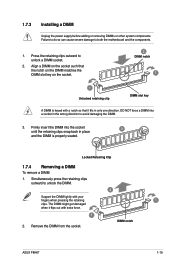
Press the retaining clips outward to both the motherboard and the components. 1. Align a DIMM on the socket such that the notch on the DIMM matches the DIMM slot key on the socket. 2 DIMM notch 1 1 ... the socket until the retaining clips snap back in place 3 and the DIMM is keyed with your fingers when pressing the retaining 1 clips. DIMM notch ASUS P8H67 1-19 Firmly insert the DIMM into a socket in only one direction. Failure to do so can cause severe damage to unlock a DIMM socket. 2. Simultaneously press...
Press the retaining clips outward to both the motherboard and the components. 1. Align a DIMM on the socket such that the notch on the DIMM matches the DIMM slot key on the socket. 2 DIMM notch 1 1 ... the socket until the retaining clips snap back in place 3 and the DIMM is keyed with your fingers when pressing the retaining 1 clips. DIMM notch ASUS P8H67 1-19 Firmly insert the DIMM into a socket in only one direction. Failure to do so can cause severe damage to unlock a DIMM socket. 2. Simultaneously press...
User Manual
Page 32
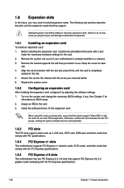
... slots that the cards do so may need IRQ assignments. 1.8 Expansion slots In the future, you may cause you physical injury and damage motherboard components. 1.8.1 Installing an expansion card To install an expansion card: 1. Align the card connector with it by adjusting the software settings. 1.... the power cord before adding or removing expansion cards. Keep the screw for the card. 2. Remove the system unit cover (if your motherboard is completely seated on the system and change the necessary BIOS settings, if any. Failure to the chassis with the PCI Express specifications....
... slots that the cards do so may need IRQ assignments. 1.8 Expansion slots In the future, you may cause you physical injury and damage motherboard components. 1.8.1 Installing an expansion card To install an expansion card: 1. Align the card connector with it by adjusting the software settings. 1.... the power cord before adding or removing expansion cards. Keep the screw for the card. 2. Remove the system unit cover (if your motherboard is completely seated on the system and change the necessary BIOS settings, if any. Failure to the chassis with the PCI Express specifications....
User Manual
Page 33
... details. • We recommend that you install two CrossFireX™ graphics cards on both the PCIe x16 slots to the motherboard connector labeled CHA_FAN1 or CHA_FAN2 when using multiple graphics cards for better thermal environment. See page 1-29 for details. • Connect a chassis fan to set up a CrossFireX™ cofiguration. ASUS P8H67 1-21
... details. • We recommend that you install two CrossFireX™ graphics cards on both the PCIe x16 slots to the motherboard connector labeled CHA_FAN1 or CHA_FAN2 when using multiple graphics cards for better thermal environment. See page 1-29 for details. • Connect a chassis fan to set up a CrossFireX™ cofiguration. ASUS P8H67 1-21
User Manual
Page 37
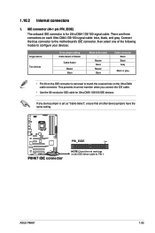
...incorrect insertion when you connect the IDE cable. • Use the 80-conductor IDE cable for Ultra DMA 133/100 signal cable. P8H67 PRI_EIDE PIN1 P8H67 IDE connector NOTE:Orient the red markings on the IDE ribbon cable to match the covered hole on the Ultra DMA cable connector. Master... is for Ultra DMA 133/100 IDE devices. ASUS P8H67 1-25 IDE connector (40-1 pin PRI_EIDE) The onboard IDE connector is set as "Cable-Select", ensure that all other device jumpers have the same setting. Connect the blue connector to the motherboard's IDE connector, then select one of the following...
...incorrect insertion when you connect the IDE cable. • Use the 80-conductor IDE cable for Ultra DMA 133/100 signal cable. P8H67 PRI_EIDE PIN1 P8H67 IDE connector NOTE:Orient the red markings on the IDE ribbon cable to match the covered hole on the Ultra DMA cable connector. Master... is for Ultra DMA 133/100 IDE devices. ASUS P8H67 1-25 IDE connector (40-1 pin PRI_EIDE) The onboard IDE connector is set as "Cable-Select", ensure that all other device jumpers have the same setting. Connect the blue connector to the motherboard's IDE connector, then select one of the following...


