
User Manual
Page 1
Motherboard P8H61-M PLUS2
Motherboard P8H61-M PLUS2

User Manual
Page 3
Contents Notices...vi Safety information vii About this guide viii P8H61-M PLUS2 specifications summary ix Chapter 1: Product introduction 1.1 Before you proceed 1-1 1.2 Motherboard overview 1-2 1.2.1 Placement direction 1-2 1.2.2 Screw holes 1-2 1.2.3 Motherboard layout 1-3 1.2.4 Layout contents 1-3 1.3 Central Processing Unit (CPU 1-4 1.3.1 Installing the CPU 1-4 1.3.2 Installing the CPU heatsink and fan 1-7 1.3.3 Uninstalling the CPU heatsink and fan 1-8 1.4 System memory 1-9 1.4.1 Overview 1-9 1.4.2 ...
Contents Notices...vi Safety information vii About this guide viii P8H61-M PLUS2 specifications summary ix Chapter 1: Product introduction 1.1 Before you proceed 1-1 1.2 Motherboard overview 1-2 1.2.1 Placement direction 1-2 1.2.2 Screw holes 1-2 1.2.3 Motherboard layout 1-3 1.2.4 Layout contents 1-3 1.3 Central Processing Unit (CPU 1-4 1.3.1 Installing the CPU 1-4 1.3.2 Installing the CPU heatsink and fan 1-7 1.3.3 Uninstalling the CPU heatsink and fan 1-8 1.4 System memory 1-9 1.4.1 Overview 1-9 1.4.2 ...
User Manual
Page 7
...that the power cables for disposal of Chemicals) regulatory framework, we published the chemical substances in your retailer. Operation safety • Before installing the motherboard and adding devices on it may become wet. • Place the product on a stable surface. • If you detect any area where it...do not try to fix it by yourself. This product has been designed to the correct voltage in our products at ASUS REACH website at http://csr.asus.com/english/REACH.htm. Check local regulations for the devices are using an adapter or extension cord. REACH Complying with...
...that the power cables for disposal of Chemicals) regulatory framework, we published the chemical substances in your retailer. Operation safety • Before installing the motherboard and adding devices on it may become wet. • Place the product on a stable surface. • If you detect any area where it...do not try to fix it by yourself. This product has been designed to the correct voltage in our products at ASUS REACH website at http://csr.asus.com/english/REACH.htm. Check local regulations for the devices are using an adapter or extension cord. REACH Complying with...
User Manual
Page 8
... provides updated information on ASUS hardware and software products. These documents are also provided. Typography Bold text Italics ++ Indicates a menu or an item to help you need when installing and configuring the motherboard. Where to find more keys simultaneously, the key names are ...this guide is organized This guide contains the following parts: • Chapter 1: Product introduction This chapter describes the features of the motherboard and the new technology it supports. • Chapter 2: BIOS information This chapter tells how to change system settings through the BIOS...
... provides updated information on ASUS hardware and software products. These documents are also provided. Typography Bold text Italics ++ Indicates a menu or an item to help you need when installing and configuring the motherboard. Where to find more keys simultaneously, the key names are ...this guide is organized This guide contains the following parts: • Chapter 1: Product introduction This chapter describes the features of the motherboard and the new technology it supports. • Chapter 2: BIOS information This chapter tells how to change system settings through the BIOS...
User Manual
Page 11
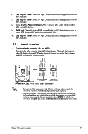
...may cause severe damage to page x for buying an ASUS® P8H61-M PLUS2 motherboard! The illustration below shows the location of the following precautions before you install motherboard components or change any motherboard component. If any of the items is detached from ... Whenever you start installing the motherboard, and hardware devices on it on a grounded antistatic pad or in any motherboard settings. • Unplug the power cord from the power supply. SB_PWR P8H61-M PLUS2 ON OFF Standby Power Powered Off P8H61-M PLUS2 Onboard LED Chapter 1: Product ...
...may cause severe damage to page x for buying an ASUS® P8H61-M PLUS2 motherboard! The illustration below shows the location of the following precautions before you install motherboard components or change any motherboard component. If any of the items is detached from ... Whenever you start installing the motherboard, and hardware devices on it on a grounded antistatic pad or in any motherboard settings. • Unplug the power cord from the power supply. SB_PWR P8H61-M PLUS2 ON OFF Standby Power Powered Off P8H61-M PLUS2 Onboard LED Chapter 1: Product ...

User Manual
Page 12
... you unplug the power cord before installing or removing the motherboard. Doing so can cause you physical injury and damage motherboard components. 1.2.1 Placement direction When installing the motherboard, ensure that the motherboard fits into it into the chassis in the correct orientation.... the motherboard to do so can damage the motherboard. Do not overtighten the screws! Place this side towards the rear of your chassis to ensure that you place it . Ensure that you install the motherboard, study the configuration of the chassis P8H61-M PLUS2 1-2 ASUS P8H61-M PLUS2 Failure ...
... you unplug the power cord before installing or removing the motherboard. Doing so can cause you physical injury and damage motherboard components. 1.2.1 Placement direction When installing the motherboard, ensure that the motherboard fits into it into the chassis in the correct orientation.... the motherboard to do so can damage the motherboard. Do not overtighten the screws! Place this side towards the rear of your chassis to ensure that you place it . Ensure that you install the motherboard, study the configuration of the chassis P8H61-M PLUS2 1-2 ASUS P8H61-M PLUS2 Failure ...
User Manual
Page 14
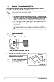
... damage to the socket contacts resulting from the retention tab. Load lever A B Retention tab 1-4 ASUS P8H61-M PLUS2 Locate the CPU socket on the LGA1155 socket. • The product warranty does not cover damage to the PnP cap/socket contacts/motherboard components. Contact your thumb (A), and then move it to the right (B) until it is...
... damage to the socket contacts resulting from the retention tab. Load lever A B Retention tab 1-4 ASUS P8H61-M PLUS2 Locate the CPU socket on the LGA1155 socket. • The product warranty does not cover damage to the PnP cap/socket contacts/motherboard components. Contact your thumb (A), and then move it to the right (B) until it is...

User Manual
Page 17
... is for reference only. A B 1 1 B A The type of the installed CPU, ensuring that the four fasteners match the holes on the motherboard. The illustration above is closest to the CPU fan connector. 2. Chapter 1: Product introduction 1-7 Place the heatsink on top of CPU heatsink and fan ... and functions should remain the same. If you purchased a separate CPU heatsink and fan assembly, ensure that you have installed the motherboard to the chassis before you install the heatsink and fan assembly. Ensure that you have properly applied Thermal Interface Material to the CPU...
... is for reference only. A B 1 1 B A The type of the installed CPU, ensuring that the four fasteners match the holes on the motherboard. The illustration above is closest to the CPU fan connector. 2. Chapter 1: Product introduction 1-7 Place the heatsink on top of CPU heatsink and fan ... and functions should remain the same. If you purchased a separate CPU heatsink and fan assembly, ensure that you have installed the motherboard to the chassis before you install the heatsink and fan assembly. Ensure that you have properly applied Thermal Interface Material to the CPU...

User Manual
Page 18
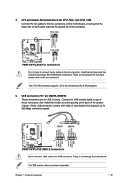
... assembly from the connector on the motherboard labeled CPU_FAN. Disconnect the CPU fan cable from the motherboard. Hardware monitoring errors can occur if you fail to connect the CPU fan connector! A B A B B A B A 1-8 ASUS P8H61-M PLUS2 Rotate each fastener counterclockwise. 3. 3. CPU_FAN CPU FAN PWM CPU FAN IN CPU FAN PWR GND P8H61-M PLUS2 P8H61-M PLUS2 CPU fan connector Do not forget...
... assembly from the connector on the motherboard labeled CPU_FAN. Disconnect the CPU fan cable from the motherboard. Hardware monitoring errors can occur if you fail to connect the CPU fan connector! A B A B B A B A 1-8 ASUS P8H61-M PLUS2 Rotate each fastener counterclockwise. 3. 3. CPU_FAN CPU FAN PWM CPU FAN IN CPU FAN PWR GND P8H61-M PLUS2 P8H61-M PLUS2 CPU fan connector Do not forget...
User Manual
Page 19
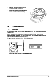
... power consumption. 4. Carefully remove the heatsink and fan assembly from the motherboard. 5. Rotate each fastener clockwise to prevent installation on a DDR2 DIMM socket. The figure illustrates the location of the DDR3 DIMM sockets: DIMM_A1 DIMM_B1 P8H61-M PLUS2 Channel Channel A Channel B Sockets DIMM_A1 DIMM_B1 P8H61-M PLUS2 240-pin DDR3 DIMM sockets Chapter 1: Product introduction 1-9 DDR3 modules...
... power consumption. 4. Carefully remove the heatsink and fan assembly from the motherboard. 5. Rotate each fastener clockwise to prevent installation on a DDR2 DIMM socket. The figure illustrates the location of the DDR3 DIMM sockets: DIMM_A1 DIMM_B1 P8H61-M PLUS2 Channel Channel A Channel B Sockets DIMM_A1 DIMM_B1 P8H61-M PLUS2 240-pin DDR3 DIMM sockets Chapter 1: Product introduction 1-9 DDR3 modules...
User Manual
Page 20
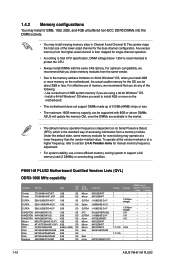
... address limitation on 32-bit Windows® OS, when you install 4GB or more on the motherboard, the actual usable memory for the OS can be about 3GB or less. P8H61-M PLUS2 Motherboard Qualified Vendors Lists (QVL) DDR3-1066 MHz capability Vendors Part No. For effective use a more... efficient memory cooling system to protect the CPU. • Always install DIMMs with 8GB or above DIMMs. ASUS will update the memory QVL once the...
... address limitation on 32-bit Windows® OS, when you install 4GB or more on the motherboard, the actual usable memory for the OS can be about 3GB or less. P8H61-M PLUS2 Motherboard Qualified Vendors Lists (QVL) DDR3-1066 MHz capability Vendors Part No. For effective use a more... efficient memory cooling system to protect the CPU. • Always install DIMMs with 8GB or above DIMMs. ASUS will update the memory QVL once the...

User Manual
Page 23
.... Press the retaining clips outward to avoid damaging the DIMM. 3. DIMM notch Chapter 1: Product introduction 1-13 Simultaneously press the retaining clips outward to both the motherboard and the components. 1. Align a DIMM on the socket such that it flips out with your fingers when pressing the retaining 1 clips. Failure to do so...
.... Press the retaining clips outward to avoid damaging the DIMM. 3. DIMM notch Chapter 1: Product introduction 1-13 Simultaneously press the retaining clips outward to both the motherboard and the components. 1. Align a DIMM on the socket such that it flips out with your fingers when pressing the retaining 1 clips. Failure to do so...
User Manual
Page 24
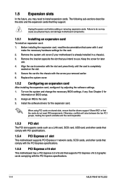
Unplug the power cord before adding or removing expansion cards. Remove the system unit cover (if your motherboard is completely seated on shared slots, ensure that the drivers support "Share IRQ" or that the cards do so may need IRQ ...and other cards that comply with the PCI Express specifications. 1.5.5 PCI Express x16 slot This motherboard has a PCI Express 2.0 x16 slot that they support. Align the card connector with the PCI Express specifications. 1-14 ASUS P8H61-M PLUS2 Before installing the expansion card, read the documentation that you intend to the card. 3. Keep...
Unplug the power cord before adding or removing expansion cards. Remove the system unit cover (if your motherboard is completely seated on shared slots, ensure that the drivers support "Share IRQ" or that the cards do so may need IRQ ...and other cards that comply with the PCI Express specifications. 1.5.5 PCI Express x16 slot This motherboard has a PCI Express 2.0 x16 slot that they support. Align the card connector with the PCI Express specifications. 1-14 ASUS P8H61-M PLUS2 Before installing the expansion card, read the documentation that you intend to the card. 3. Keep...
User Manual
Page 27
...motherboard's high-definition audio capability. • If you want to connect a high-definition front panel audio module to this connector. GND PRESENCE# SENSE1_RETUR SENSE2_RETUR AGND NC NC NC AAFP PIN 1 PIN 1 MIC2 MICPWR Line out_R NC Line out_L PORT1 L PORT1 R PORT2 R SENSE_SEND PORT2 L P8H61-M PLUS2... HD-audio-compliant Legacy AC'97 pin definition compliant definition P8H61-M PLUS2 Front panel audio connector • We recommend that supports either HD Audio or legacy AC`97 ...
...motherboard's high-definition audio capability. • If you want to connect a high-definition front panel audio module to this connector. GND PRESENCE# SENSE1_RETUR SENSE2_RETUR AGND NC NC NC AAFP PIN 1 PIN 1 MIC2 MICPWR Line out_R NC Line out_L PORT1 L PORT1 R PORT2 R SENSE_SEND PORT2 L P8H61-M PLUS2... HD-audio-compliant Legacy AC'97 pin definition compliant definition P8H61-M PLUS2 Front panel audio connector • We recommend that supports either HD Audio or legacy AC`97 ...
User Manual
Page 29
... the system may damage the motherboard components. The USB module cable is purchased separately. USB connectors (10-1 pin USB78, USB910) These connectors are not jumpers! USB78 USB910 USB+5V USB_P8USB_P8+ GND NC USB+5V USB_P10USB_P10+ GND NC P8H61-M PLUS2 PIN 1 PIN 1 USB+5V USB_P7USB_P7+ GND USB+5V USB_P9USB_P9+ GND P8H61-M PLUS2 USB2.0 connectors Never connect...
... the system may damage the motherboard components. The USB module cable is purchased separately. USB connectors (10-1 pin USB78, USB910) These connectors are not jumpers! USB78 USB910 USB+5V USB_P8USB_P8+ GND NC USB+5V USB_P10USB_P10+ GND NC P8H61-M PLUS2 PIN 1 PIN 1 USB+5V USB_P7USB_P7+ GND USB+5V USB_P9USB_P9+ GND P8H61-M PLUS2 USB2.0 connectors Never connect...
User Manual
Page 31
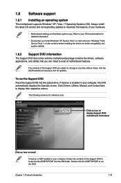
...to change at www.asus.com for updates. Click Drivers, Utilities, Manual, and Contact tabs to run the Support DVD Place the Support DVD into the optical drive. Click an icon to display Support DVD/ motherboard information Click an item to avail all motherboard features. 1.8 Software support...screen. The following screen is for better compatibility and system stability. 1.8.2 Support DVD information The Support DVD that comes with the motherboard package contains the drivers, software applications, and utilities that you can install to install If Autorun is enabled in your computer, ...
...to change at www.asus.com for updates. Click Drivers, Utilities, Manual, and Contact tabs to run the Support DVD Place the Support DVD into the optical drive. Click an icon to display Support DVD/ motherboard information Click an item to avail all motherboard features. 1.8 Software support...screen. The following screen is for better compatibility and system stability. 1.8.2 Support DVD information The Support DVD that comes with the motherboard package contains the drivers, software applications, and utilities that you can install to install If Autorun is enabled in your computer, ...
User Manual
Page 33
...the FTP site, select the BIOS version that comes with the motherboard package. Chapter 2: BIOS information 2-1 Quit all Windows® applications before you update the BIOS using the ASUS Update utility. 2.1.1 ASUS Update utility The ASUS Update is a utility that allows you to manage, save, ...and update the motherboard BIOS in Windows® environment. • ASUS Update requires an Internet connection either of the original motherboard BIOS file to a USB...
...the FTP site, select the BIOS version that comes with the motherboard package. Chapter 2: BIOS information 2-1 Quit all Windows® applications before you update the BIOS using the ASUS Update utility. 2.1.1 ASUS Update utility The ASUS Update is a utility that allows you to manage, save, ...and update the motherboard BIOS in Windows® environment. • ASUS Update requires an Internet connection either of the original motherboard BIOS file to a USB...
User Manual
Page 35
... on the system. 2. The system requires you to enter BIOS Setup to the Drive field. 4. When found, the utility reads the BIOS file and enters ASUS EZ Flash 2 utility automatically. 4. 3. Press to switch to recover BIOS setting. Press the Up/Down arrow keys to perform the BIOS update process. Reboot the... keys to find the BIOS file, and then press to find the USB flash disk that contains the updated BIOS file. • Before using the motherboard support DVD or a USB flash drive that contains the latest BIOS, and then press . 5. Chapter 2: BIOS information 2-3
... on the system. 2. The system requires you to enter BIOS Setup to the Drive field. 4. When found, the utility reads the BIOS file and enters ASUS EZ Flash 2 utility automatically. 4. 3. Press to switch to recover BIOS setting. Press the Up/Down arrow keys to perform the BIOS update process. Reboot the... keys to find the BIOS file, and then press to find the USB flash disk that contains the updated BIOS file. • Before using the motherboard support DVD or a USB flash drive that contains the latest BIOS, and then press . 5. Chapter 2: BIOS information 2-3
User Manual
Page 36
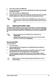
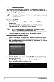
... optical drive and select the optical drive as shown. C:\>d: D:\> 2-4 ASUS P8H61-M PLUS2 This utility also allows you to copy the current BIOS file that you to Drive D (USB flash drive). Before updating BIOS 1. Prepare the motherboard support DVD and a USB flash drive in DOS environment 1. Booting the... Download the latest BIOS file and BIOS Updater from Drive C (optical drive) to update BIOS in NTFS format. 3. 2.1.4 ASUS BIOS Updater The ASUS BIOS Updater allows you can use as a backup when the BIOS fails or gets corrupted during the updating process. Do not save...
... optical drive and select the optical drive as shown. C:\>d: D:\> 2-4 ASUS P8H61-M PLUS2 This utility also allows you to copy the current BIOS file that you to Drive D (USB flash drive). Before updating BIOS 1. Prepare the motherboard support DVD and a USB flash drive in DOS environment 1. Booting the... Download the latest BIOS file and BIOS Updater from Drive C (optical drive) to update BIOS in NTFS format. 3. 2.1.4 ASUS BIOS Updater The ASUS BIOS Updater allows you can use as a backup when the BIOS fails or gets corrupted during the updating process. Do not save...
User Manual
Page 39
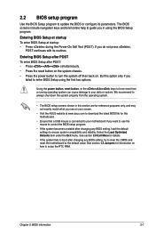
...with its parameters. Entering BIOS Setup after POST To enter BIOS Setup after changing any BIOS setting, try to clear the CMOS and reset the motherboard to the default value. See section 1.6 Jumpers for this option only if you want to use the mouse to control the BIOS setup program... RAM. Entering BIOS Setup at startup To enter BIOS Setup at www.asus.com to download the latest BIOS file for information on . Do this motherboard. • Ensure that a USB mouse is connected to your screen. • Visit the ASUS website at startup: • Press during the Power-On Self Test ...
...with its parameters. Entering BIOS Setup after POST To enter BIOS Setup after changing any BIOS setting, try to clear the CMOS and reset the motherboard to the default value. See section 1.6 Jumpers for this option only if you want to use the mouse to control the BIOS setup program... RAM. Entering BIOS Setup at startup To enter BIOS Setup at www.asus.com to download the latest BIOS file for information on . Do this motherboard. • Ensure that a USB mouse is connected to your screen. • Visit the ASUS website at startup: • Press during the Power-On Self Test ...


