P8H61-M LX PLUS R2 User's Manual
Page 1
Motherboard P8H61-M LX R2.0 Series • P8H61-M LX R2.0 • P8H61-M PLUS R2.0
Motherboard P8H61-M LX R2.0 Series • P8H61-M LX R2.0 • P8H61-M PLUS R2.0
P8H61-M LX PLUS R2 User's Manual
Page 3
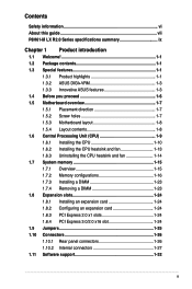
Contents Safety information vi About this guide vii P8H61-M LX R2.0 Series specifications summary ix Chapter 1 Product introduction 1.1 Welcome 1-1 1.2 Package contents 1-1 1.3 Special features 1-1 1.3.1 Product highlights 1-1 1.3.2 ASUS DIGI+VRM 1-3 1.3.3 Innovative ASUS features 1-3 1.4 Before you proceed 1-6 1.5 Motherboard overview 1-7 1.5.1 Placement direction 1-7 1.5.2 Screw holes 1-7 1.5.3 Motherboard layout 1-8 1.5.4 Layout contents 1-8 1.6 Central Processing Unit (CPU 1-9 1.6.1 Installing the CPU 1-10 1.6.2 Installing the CPU heatsink and fan...
Contents Safety information vi About this guide vii P8H61-M LX R2.0 Series specifications summary ix Chapter 1 Product introduction 1.1 Welcome 1-1 1.2 Package contents 1-1 1.3 Special features 1-1 1.3.1 Product highlights 1-1 1.3.2 ASUS DIGI+VRM 1-3 1.3.3 Innovative ASUS features 1-3 1.4 Before you proceed 1-6 1.5 Motherboard overview 1-7 1.5.1 Placement direction 1-7 1.5.2 Screw holes 1-7 1.5.3 Motherboard layout 1-8 1.5.4 Layout contents 1-8 1.6 Central Processing Unit (CPU 1-9 1.6.1 Installing the CPU 1-10 1.6.2 Installing the CPU heatsink and fan...

P8H61-M LX PLUS R2 User's Manual
Page 6
...disconnect all power cables from the existing system before you add a device. • Before connecting or removing signal cables from the motherboard, ensure that all power cables are using an adapter or extension cord. Safety information Electrical safety • To prevent electric shock ... the product, ensure that all cables are correctly connected and the power cables are connected. Operation safety • Before installing the motherboard and adding components, carefully read all the manuals that came with the product, contact a qualified service technician or your retailer. If...
...disconnect all power cables from the existing system before you add a device. • Before connecting or removing signal cables from the motherboard, ensure that all power cables are using an adapter or extension cord. Safety information Electrical safety • To prevent electric shock ... the product, ensure that all cables are correctly connected and the power cables are connected. Operation safety • Before installing the motherboard and adding components, carefully read all the manuals that came with the product, contact a qualified service technician or your retailer. If...
P8H61-M LX PLUS R2 User's Manual
Page 7
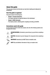
... symbols used throughout this guide is organized This guide contains the following parts: • Chapter 1: Product introduction This chapter describes the supported features of the motherboard. • Chapter 2: BIOS information This chapter provides a detailed guide to navigating and setting up the BIOS. vii How this manual. DANGER/WARNING: Information to prevent... you complete a task. NOTE: Tips and additional information to complete a task. IMPORTANT: Instructions you MUST follow to help you need when installing and configuring the motherboard.
... symbols used throughout this guide is organized This guide contains the following parts: • Chapter 1: Product introduction This chapter describes the supported features of the motherboard. • Chapter 2: BIOS information This chapter provides a detailed guide to navigating and setting up the BIOS. vii How this manual. DANGER/WARNING: Information to prevent... you complete a task. NOTE: Tips and additional information to complete a task. IMPORTANT: Instructions you MUST follow to help you need when installing and configuring the motherboard.

P8H61-M LX PLUS R2 User's Manual
Page 11
... another standout in LGA1155 package with the list below. 1.2 Package contents Check your motherboard package for buying an ASUS® P8H61-M LX R2.0 Series motherboard! Before you for the following items. Motherboard Cables Accessories Application DVD Documentation ASUS P8H61-M LX 2.0 Series motherboard 2 x Serial ATA 3.0Gb/s cables 1 x I/O shield ASUS motherboard support DVD User Manual If any of the above items is damaged or missing...
... another standout in LGA1155 package with the list below. 1.2 Package contents Check your motherboard package for buying an ASUS® P8H61-M LX R2.0 Series motherboard! Before you for the following items. Motherboard Cables Accessories Application DVD Documentation ASUS P8H61-M LX 2.0 Series motherboard 2 x Serial ATA 3.0Gb/s cables 1 x I/O shield ASUS motherboard support DVD User Manual If any of the above items is damaged or missing...
P8H61-M LX PLUS R2 User's Manual
Page 12
... H61 Express Chipset is enhanced with an ACPI management function to provide efficient power management for advanced operating systems. 1-2 ASUS P8H61-M LX R2.0 The total bandwidth for users who wish to improve and optimize graphic performance, as well as have the latest technology ...PCIe 1.0 and PCIe 2.0 devices. Dual-Channel DDR3 2200(O.C.) / 2133 (O.C.) / 2000 (O.C.) / 1866 (O.C.) / 1600 / 1333 / 1066MHz support The motherboard supports DDR3 memory that provide twice the performance of the current PCIe 2.0. PCI Express® 3.0 PCI Express® 3.0 (PCIe 3.0) is a highly ...
... H61 Express Chipset is enhanced with an ACPI management function to provide efficient power management for advanced operating systems. 1-2 ASUS P8H61-M LX R2.0 The total bandwidth for users who wish to improve and optimize graphic performance, as well as have the latest technology ...PCIe 1.0 and PCIe 2.0 devices. Dual-Channel DDR3 2200(O.C.) / 2133 (O.C.) / 2000 (O.C.) / 1866 (O.C.) / 1600 / 1333 / 1066MHz support The motherboard supports DDR3 memory that provide twice the performance of the current PCIe 2.0. PCI Express® 3.0 PCI Express® 3.0 (PCIe 3.0) is a highly ...
P8H61-M LX PLUS R2 User's Manual
Page 13
... helping deliver far more stable CPU Vcore voltages. Innovative ASUS features ASUS UEFI BIOS (EZ Mode) The new ASUS UEFI BIOS is for durability, improved lifespan, and enhanced thermal capacity. ASUS EPU Tap into the world's first real-time PC power... or AI Suite II utility. Chapter 1: Product introduction 1-3 1.3.2 1.3.3 100% All High-quality Conductive Polymer Capacitors (P8H61-M LX R2.0 PLUS R2.0 only) This motherboard uses all high-quality conductive polymer capacitors for experienced performance enthusiasts that goes beyond traditional keyboardonly BIOS control to enable more...
... helping deliver far more stable CPU Vcore voltages. Innovative ASUS features ASUS UEFI BIOS (EZ Mode) The new ASUS UEFI BIOS is for durability, improved lifespan, and enhanced thermal capacity. ASUS EPU Tap into the world's first real-time PC power... or AI Suite II utility. Chapter 1: Product introduction 1-3 1.3.2 1.3.3 100% All High-quality Conductive Polymer Capacitors (P8H61-M LX R2.0 PLUS R2.0 only) This motherboard uses all high-quality conductive polymer capacitors for experienced performance enthusiasts that goes beyond traditional keyboardonly BIOS control to enable more...
P8H61-M LX PLUS R2 User's Manual
Page 14
... into a 256-color boot logo for motherboard users, but also lowers the temperature of radiation. 1. Combining usability and aesthetics, the ASUS stylish heatpipe will give users an extremely silent and cooling experience with ESD Guards. ESD ... visual enjoyment for a more reliable computing environment. ASUS Anti-Surge Protection This special design prevents expensive devices and the motherboard from damage caused by power surges from harmful electromagnetic exposure by different climate conditions in different geographic regions and your screen. 1-4 ASUS P8H61-M LX R2.0
... into a 256-color boot logo for motherboard users, but also lowers the temperature of radiation. 1. Combining usability and aesthetics, the ASUS stylish heatpipe will give users an extremely silent and cooling experience with ESD Guards. ESD ... visual enjoyment for a more reliable computing environment. ASUS Anti-Surge Protection This special design prevents expensive devices and the motherboard from damage caused by power surges from harmful electromagnetic exposure by different climate conditions in different geographic regions and your screen. 1-4 ASUS P8H61-M LX R2.0

P8H61-M LX PLUS R2 User's Manual
Page 15
... Union´s Energy-related Products (ErP) ready, and ErP requires products to meet certain energy efficiency requirements in line with ASUS vision of creating environment-friendly and energy-efficient products through product design and innovation to reduce carbon footprint of the product and thus... C.P.R. Simply shut down and reboot the system, and the BIOS automatically restores the CPU parameters to overclocking failure. ErP ready The motherboard is an auto-recovery tool that contains the latest BIOS file. feature automatically restores the CPU default settings when the system hangs due...
... Union´s Energy-related Products (ErP) ready, and ErP requires products to meet certain energy efficiency requirements in line with ASUS vision of creating environment-friendly and energy-efficient products through product design and innovation to reduce carbon footprint of the product and thus... C.P.R. Simply shut down and reboot the system, and the BIOS automatically restores the CPU parameters to overclocking failure. ErP ready The motherboard is an auto-recovery tool that contains the latest BIOS file. feature automatically restores the CPU default settings when the system hangs due...
P8H61-M LX PLUS R2 User's Manual
Page 16
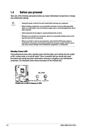
... P8H61-M LX R2.0 ON OFF Standby Power Powered Off P8H61-M LX R2.0 Onboard LED 1-6 ASUS P8H61-M LX R2.0 This is disconnected from the wall socket before removing or plugging in soft-off or the power cord is a reminder that the ATX power supply is switched off mode. The illustration below shows the location of the following precautions before you install motherboard...
... P8H61-M LX R2.0 ON OFF Standby Power Powered Off P8H61-M LX R2.0 Onboard LED 1-6 ASUS P8H61-M LX R2.0 This is disconnected from the wall socket before removing or plugging in soft-off or the power cord is a reminder that the ATX power supply is switched off mode. The illustration below shows the location of the following precautions before you install motherboard...
P8H61-M LX PLUS R2 User's Manual
Page 17
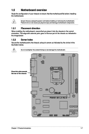
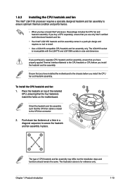
... chassis as indicated in the image below . Do not overtighten the screws! Failure to do so can damage the motherboard. The edge with external ports goes to the rear part of the chassis P8H61-M LX R2.0 Chapter 1: Product introduction 1-7 Ensure that you place it into the chassis in the illustration below . 1.5.2 Screw holes Secure...
... chassis as indicated in the image below . Do not overtighten the screws! Failure to do so can damage the motherboard. The edge with external ports goes to the rear part of the chassis P8H61-M LX R2.0 Chapter 1: Product introduction 1-7 Ensure that you place it into the chassis in the illustration below . 1.5.2 Screw holes Secure...
P8H61-M LX PLUS R2 User's Manual
Page 18
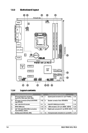
... connector (4-pin SPEAKER) 1-22 1-8 9. Clear RTC RAM (3-pin CLRTC) 1-19 1-13 10. Front panel audio connector (10-1 pin AAFP) 1-21 1-8 ASUS P8H61-M LX R2.0 Intel® H61 Serial ATA 3.0Gb/s connectors (7-pin SATA3G_1/2/3/4) 6. 1.5.3 Motherboard layout 12 3 1 4 18.3cm(7.2in) KBMS DIGI +VRM CPU_FAN COM ATX12V DDR3 DIMM_A1 (64bit, 240-pin module) DDR3 DIMM_B1 (64bit, 240...
... connector (4-pin SPEAKER) 1-22 1-8 9. Clear RTC RAM (3-pin CLRTC) 1-19 1-13 10. Front panel audio connector (10-1 pin AAFP) 1-21 1-8 ASUS P8H61-M LX R2.0 Intel® H61 Serial ATA 3.0Gb/s connectors (7-pin SATA3G_1/2/3/4) 6. 1.5.3 Motherboard layout 12 3 1 4 18.3cm(7.2in) KBMS DIGI +VRM CPU_FAN COM ATX12V DDR3 DIMM_A1 (64bit, 240-pin module) DDR3 DIMM_B1 (64bit, 240...
P8H61-M LX PLUS R2 User's Manual
Page 19
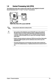
... cover damage to the PnP cap/socket contacts/motherboard components. ASUS will process Return Merchandise Authorization (RMA) requests only if the motherboard comes with a surface mount LGA1155 socket designed for the Intel® Second Generation Core™ i7 / Core™ i5 / Core™ i3 processors. P8H61-M LX R2.0 P8H61-M LX R2.0 CPU socket LGA1155 Unplug all power cables before...
... cover damage to the PnP cap/socket contacts/motherboard components. ASUS will process Return Merchandise Authorization (RMA) requests only if the motherboard comes with a surface mount LGA1155 socket designed for the Intel® Second Generation Core™ i7 / Core™ i5 / Core™ i3 processors. P8H61-M LX R2.0 P8H61-M LX R2.0 CPU socket LGA1155 Unplug all power cables before...
P8H61-M LX PLUS R2 User's Manual
Page 20
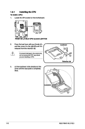
Press the load lever with your thumb (A), and then move it to the socket pins, do not remove the PnP cap unless you are installing a CPU. 3. Lift the load lever in the direction of the arrow until it is completely lifted. Locate the CPU socket on the motherboard. Load lever A B Retention tab Load plate 1-10 ASUS P8H61-M LX R2.0 1.6.1 Installing the CPU To install a CPU: 1. P8H61-M LX R2.0 P8H61-M LX R2.0 CPU socket LGA1155 2. To prevent damage to the right (B) until the load plate is released from the retention tab.
Press the load lever with your thumb (A), and then move it to the socket pins, do not remove the PnP cap unless you are installing a CPU. 3. Lift the load lever in the direction of the arrow until it is completely lifted. Locate the CPU socket on the motherboard. Load lever A B Retention tab Load plate 1-10 ASUS P8H61-M LX R2.0 1.6.1 Installing the CPU To install a CPU: 1. P8H61-M LX R2.0 P8H61-M LX R2.0 CPU socket LGA1155 2. To prevent damage to the right (B) until the load plate is released from the retention tab.
P8H61-M LX PLUS R2 User's Manual
Page 23
...incompatible with the LGA775 and LGA1366 sockets in size and dimension. Orient the heatsink and fan assembly such that you have installed the motherboard to the chassis before you buy a CPU separately, ensure that you have properly applied Thermal Interface Material to install. • ... CPU heatsink and fan assembly only. Chapter 1: Product introduction 1-13 The LGA1155 socket is for reference only. Place the heatsink on the motherboard. Ensure that you install the heatsink and fan assembly. Push down two fasteners at a time in a diagonal sequence to secure the heatsink...
...incompatible with the LGA775 and LGA1366 sockets in size and dimension. Orient the heatsink and fan assembly such that you have installed the motherboard to the chassis before you buy a CPU separately, ensure that you have properly applied Thermal Interface Material to install. • ... CPU heatsink and fan assembly only. Chapter 1: Product introduction 1-13 The LGA1155 socket is for reference only. Place the heatsink on the motherboard. Ensure that you install the heatsink and fan assembly. Push down two fasteners at a time in a diagonal sequence to secure the heatsink...
P8H61-M LX PLUS R2 User's Manual
Page 24
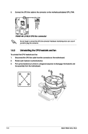
CPU_FAN CPU FAN PWM CPU FAN IN CPU FAN PWR GND P8H61-M LX R2.0 P8H61-M LX R2.0 CPU fan connector Do not forget to disengage the heatsink and fan assembly from the connector on the motherboard labeled CPU_FAN. Pull up two fasteners at a time in a diagonal sequence to connect the CPU fan connector! Connect ...this connector. 1.6.3 Uninstalling the CPU heatsink and fan To uninstall the CPU heatsink and fan: 1. Disconnect the CPU fan cable from the motherboard. A B A B B A B A 1-14 ASUS P8H61-M LX R2.0 3. Hardware monitoring errors can occur if you fail to the connector on the...
CPU_FAN CPU FAN PWM CPU FAN IN CPU FAN PWR GND P8H61-M LX R2.0 P8H61-M LX R2.0 CPU fan connector Do not forget to disengage the heatsink and fan assembly from the connector on the motherboard labeled CPU_FAN. Pull up two fasteners at a time in a diagonal sequence to connect the CPU fan connector! Connect ...this connector. 1.6.3 Uninstalling the CPU heatsink and fan To uninstall the CPU heatsink and fan: 1. Disconnect the CPU fan cable from the motherboard. A B A B B A B A 1-14 ASUS P8H61-M LX R2.0 3. Hardware monitoring errors can occur if you fail to the connector on the...
P8H61-M LX PLUS R2 User's Manual
Page 25
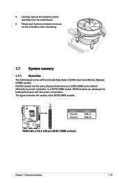
... location of the DDR3 DIMM sockets: DIMM_A1 DIMM_B1 P8H61-M LX R2.0 Channel Channel A Channel B Sockets DIMM_A1 DIMM_B1 P8H61-M LX R2.0 240-pin DDR3 DIMM sockets Chapter 1: Product introduction 1-15 Rotate each fastener clockwise to prevent installation on a DDR2 DIMM socket. Carefully remove the heatsink and fan assembly from the motherboard. 5. A DDR3 module has the same physical dimensions...
... location of the DDR3 DIMM sockets: DIMM_A1 DIMM_B1 P8H61-M LX R2.0 Channel Channel A Channel B Sockets DIMM_A1 DIMM_B1 P8H61-M LX R2.0 240-pin DDR3 DIMM sockets Chapter 1: Product introduction 1-15 Rotate each fastener clockwise to prevent installation on a DDR2 DIMM socket. Carefully remove the heatsink and fan assembly from the motherboard. 5. A DDR3 module has the same physical dimensions...

P8H61-M LX PLUS R2 User's Manual
Page 26
... of memory, we recommend that use a more efficient memory cooling system to Intel CPU specification, DIMM voltage below 1.65V is dependent on the motherboard, the actual usable memory for the latest QVL. 1-16 ASUS P8H61-M LX R2.0 The system maps the total size of the following: - To operate at the vendor-marked or at www...
... of memory, we recommend that use a more efficient memory cooling system to Intel CPU specification, DIMM voltage below 1.65V is dependent on the motherboard, the actual usable memory for the latest QVL. 1-16 ASUS P8H61-M LX R2.0 The system maps the total size of the following: - To operate at the vendor-marked or at www...
P8H61-M LX PLUS R2 User's Manual
Page 27
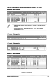
... memory module will run at DDR3 2000/1800 MHz frequency. DS - - Size SS/DS Chip Brand GET34GB2200C9DC(XMP) 2GB GET38GB2200C9ADC(XMP) 4GB DS DS - P8H61-M LX R2.0 Series Motherboard Qualified Vendors Lists (QVL) DDR3-2400 MHz capability Vendors CORSAIR G.SKILL G.SKILL GEIL KINGMAX Transcend Transcend Transcend PATRIOT Part No. KHX2250C9D3T1K2/4GX(XMP) Size 4GB...
... memory module will run at DDR3 2000/1800 MHz frequency. DS - - Size SS/DS Chip Brand GET34GB2200C9DC(XMP) 2GB GET38GB2200C9ADC(XMP) 4GB DS DS - P8H61-M LX R2.0 Series Motherboard Qualified Vendors Lists (QVL) DDR3-2400 MHz capability Vendors CORSAIR G.SKILL G.SKILL GEIL KINGMAX Transcend Transcend Transcend PATRIOT Part No. KHX2250C9D3T1K2/4GX(XMP) Size 4GB...
P8H61-M LX PLUS R2 User's Manual
Page 33
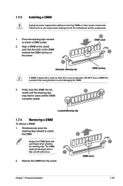
Press the retaining clips outward to both the motherboard and the components. 1. Firmly insert the DIMM into a socket in place and the DIMM is keyed with a notch so that the notch on the DIMM ...
Press the retaining clips outward to both the motherboard and the components. 1. Firmly insert the DIMM into a socket in place and the DIMM is keyed with a notch so that the notch on the DIMM ...


