
User Manual
Page 11
... a grounded antistatic pad or in the bag that came with a standby power LED that lights up to page x for buying an ASUS® P8H61-I Onboard LED 1-1 Chapter 1: Product introduction Onboard LED This motherboard comes with the component. • Before you install or remove any ..., such as the power supply case, to avoid damaging them . • Whenever you uninstall any motherboard component. SB_PWR P8H61-I ON OFF Standby Power Powered Off P8H61-I motherboard! The illustration below shows the location of the onboard LED. Chapter 1 Product introduction Thank you for the list...
... a grounded antistatic pad or in the bag that came with a standby power LED that lights up to page x for buying an ASUS® P8H61-I Onboard LED 1-1 Chapter 1: Product introduction Onboard LED This motherboard comes with the component. • Before you install or remove any ..., such as the power supply case, to avoid damaging them . • Whenever you uninstall any motherboard component. SB_PWR P8H61-I ON OFF Standby Power Powered Off P8H61-I motherboard! The illustration below shows the location of the onboard LED. Chapter 1 Product introduction Thank you for the list...

User Manual
Page 12
... CHA_FAN) 6. System panel connector (10-1 pin F_PANEL) 1-15 1-12 8. ATX power connectors (24-pin EATXPWR, 4-pin ATX12V) 3. Front panel audio connector (10-1 pin AAFP) 1-16 1-3 ASUS P8H61-I USB34 ASM 1042 LAN1_USB3_12 AUDIO RTL 8111E AAFP VIA VT1708S SPDIF_OUT LGA1155 EPU PCI1EX16 2 F_PANEL 7 SB_PWR 8 CLRTC 11 10 9 Place four screws into the chassis... SATA4 32Mb BIOS Lithium Cell CMOS Power ATX12V EATXPWR 17.1cm(6.75in) DDR3 DIMM_B1 (64bit, 240-pin module) DDR3 DIMM_A1 (64bit, 240-pin module) DVI_VGA P8H61-I 1-2
... CHA_FAN) 6. System panel connector (10-1 pin F_PANEL) 1-15 1-12 8. ATX power connectors (24-pin EATXPWR, 4-pin ATX12V) 3. Front panel audio connector (10-1 pin AAFP) 1-16 1-3 ASUS P8H61-I USB34 ASM 1042 LAN1_USB3_12 AUDIO RTL 8111E AAFP VIA VT1708S SPDIF_OUT LGA1155 EPU PCI1EX16 2 F_PANEL 7 SB_PWR 8 CLRTC 11 10 9 Place four screws into the chassis... SATA4 32Mb BIOS Lithium Cell CMOS Power ATX12V EATXPWR 17.1cm(6.75in) DDR3 DIMM_B1 (64bit, 240-pin module) DDR3 DIMM_A1 (64bit, 240-pin module) DVI_VGA P8H61-I 1-2

User Manual
Page 14
... section 2.4 Ai Tweaker menu for manual memory frequency adjustment. • For system stability, use of memory, we recommend that you do any of the following: - ASUS P8H61-I 1-4 The system maps the total size of the lower-sized channel for the dual-channel configuration.
... section 2.4 Ai Tweaker menu for manual memory frequency adjustment. • For system stability, use of memory, we recommend that you do any of the following: - ASUS P8H61-I 1-4 The system maps the total size of the lower-sized channel for the dual-channel configuration.

User Manual
Page 18
... the card to the card. 3. Assign an IRQ to the chassis with the slot and press firmly until the card is already installed in a chassis). 3. ASUS P8H61-I 1-8 Unplug the power cord before adding or removing expansion cards. Remove the system unit cover (if your motherboard is completely seated on shared slots, ensure...
... the card to the card. 3. Assign an IRQ to the chassis with the slot and press firmly until the card is already installed in a chassis). 3. ASUS P8H61-I 1-8 Unplug the power cord before adding or removing expansion cards. Remove the system unit cover (if your motherboard is completely seated on shared slots, ensure...

User Manual
Page 20
1.7 Connectors 1.7.1 1 Rear panel connectors 2 3 45 11 10 9 8 7 6 1. ASUS P8H61-I 1-10 PS/2 Keyboard / Mouse Combo port. Line In port (light blue). LAN (RJ-45) port. Microphone port (pink). This port allows Gigabit connection to a headphone ...
1.7 Connectors 1.7.1 1 Rear panel connectors 2 3 45 11 10 9 8 7 6 1. ASUS P8H61-I 1-10 PS/2 Keyboard / Mouse Combo port. Line In port (light blue). LAN (RJ-45) port. Microphone port (pink). This port allows Gigabit connection to a headphone ...

User Manual
Page 22
... Volts +12 Volts +12 Volts +5V Standby Power OK PIN 1 GND +5 Volts GND +5 Volts GND +3 Volts +3 Volts PIN 1 GND GND P8H61-I P8H61-I 1-12 ASUS P8H61-I ATX power connectors GND +5 Volts +5 Volts +5 Volts -5 Volts GND GND GND PSON# GND -12 Volts +3 Volts • For a fully ... are uncertain about the minimum power supply requirement for your system, refer to the Recommended Power Supply Wattage Calculator at http://support.asus. 1.7.2 Internal connectors 1. ATX power connectors (24-pin EATXPWR, 4-pin ATX12V) These connectors are designed to connect the 4-pin...
... Volts +12 Volts +12 Volts +5V Standby Power OK PIN 1 GND +5 Volts GND +5 Volts GND +3 Volts +3 Volts PIN 1 GND GND P8H61-I P8H61-I 1-12 ASUS P8H61-I ATX power connectors GND +5 Volts +5 Volts +5 Volts -5 Volts GND GND GND PSON# GND -12 Volts +3 Volts • For a fully ... are uncertain about the minimum power supply requirement for your system, refer to the Recommended Power Supply Wattage Calculator at http://support.asus. 1.7.2 Internal connectors 1. ATX power connectors (24-pin EATXPWR, 4-pin ATX12V) These connectors are designed to connect the 4-pin...

User Manual
Page 24
... ATA 3.0 Gb/s hard disk drives and optical drives via Serial ATA 3.0 Gb/s signal cables. SATA1 SATA2 SATA3 SATA4 P8H61-I 1-14 GND RSATA_TXP3 RSATA_TXN3 GND RSATA_RXP3 RSATA_RXN3 GND P8H61-I GND RSATA_TXP4 RSATA_TXN4 GND RSATA_RXP4 RSATA_RXN4 GND ASUS P8H61-I SATA connectors • When using Serial ATA. Intel® H61 Serial ATA 3.0Gb/s connectors (7-pin SATA3G_1/2/3/4 [blue...
... ATA 3.0 Gb/s hard disk drives and optical drives via Serial ATA 3.0 Gb/s signal cables. SATA1 SATA2 SATA3 SATA4 P8H61-I 1-14 GND RSATA_TXP3 RSATA_TXN3 GND RSATA_RXP3 RSATA_RXN3 GND P8H61-I GND RSATA_TXP4 RSATA_TXN4 GND RSATA_RXP4 RSATA_RXN4 GND ASUS P8H61-I SATA connectors • When using Serial ATA. Intel® H61 Serial ATA 3.0Gb/s connectors (7-pin SATA3G_1/2/3/4 [blue...
User Manual
Page 26
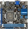
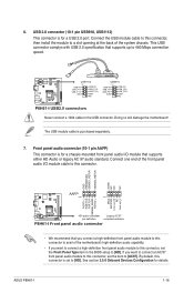
...USB module cable is set to [HD]. Connect one end of the system chassis. 6. By default, this connector is purchased separately. 7. ASUS P8H61-I /O module cable to this connector, set the Front Panel Type item in the BIOS setup to the USB connector. GND PRESENCE# SENSE1_RETUR ...AAFP PIN 1 PIN 1 MIC2 MICPWR Line out_R NC Line out_L PORT1 L PORT1 R PORT2 R SENSE_SEND PORT2 L P8H61-I HD-audio-compliant Legacy AC'97 pin definition compliant definition P8H61-I USB2.0 connectors Never connect a 1394 cable to [HD]. If you want to connect an AC'97 front panel...
...USB module cable is set to [HD]. Connect one end of the system chassis. 6. By default, this connector is purchased separately. 7. ASUS P8H61-I /O module cable to this connector, set the Front Panel Type item in the BIOS setup to the USB connector. GND PRESENCE# SENSE1_RETUR ...AAFP PIN 1 PIN 1 MIC2 MICPWR Line out_R NC Line out_L PORT1 L PORT1 R PORT2 R SENSE_SEND PORT2 L P8H61-I HD-audio-compliant Legacy AC'97 pin definition compliant definition P8H61-I USB2.0 connectors Never connect a 1394 cable to [HD]. If you want to connect an AC'97 front panel...

User Manual
Page 28
... engaging digital content such as music, videos, games, magazines, e-books, as well as a value-added service for all ASUS products. ASUS P8H61-I 1-18 To launch ASUS @Vibe ,click Start > All Programs > ASUS > ASUS VIBE > ASUS VIBE. Visit the ASUS website at www.asusvibe.com for each territory. • This utility does not work on Windows® 64-bit...
... engaging digital content such as music, videos, games, magazines, e-books, as well as a value-added service for all ASUS products. ASUS P8H61-I 1-18 To launch ASUS @Vibe ,click Start > All Programs > ASUS > ASUS VIBE > ASUS VIBE. Visit the ASUS website at www.asusvibe.com for each territory. • This utility does not work on Windows® 64-bit...
User Manual
Page 30
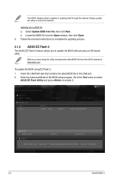
...Insert the USB flash disk that contains the latest BIOS file to complete the updating process. 2.1.2 ASUS EZ Flash 2 The ASUS EZ Flash 2 feature allows you start using EZ Flash 2: 1. b. Updating from file, then click... the BIOS file from the ASUS website at www.asus.com. Enter the Advanced Mode of updating itself through the Internet. ASUSTek EZ Flash 2 BIOS ROM Utility V00.75 Flash Info MODEL: P8H61-I File Path: fs0:\ Drive...: 0202 Folder Info 01/18/11 05:40p 4194304 Exit DATE: 12/30/2010 P8H61-I-ASUS-0306.ROM File Info MODEL: P8H67-I Help Info VER: 0306 DATE: 01/14/11...
...Insert the USB flash disk that contains the latest BIOS file to complete the updating process. 2.1.2 ASUS EZ Flash 2 The ASUS EZ Flash 2 feature allows you start using EZ Flash 2: 1. b. Updating from file, then click... the BIOS file from the ASUS website at www.asus.com. Enter the Advanced Mode of updating itself through the Internet. ASUSTek EZ Flash 2 BIOS ROM Utility V00.75 Flash Info MODEL: P8H61-I File Path: fs0:\ Drive...: 0202 Folder Info 01/18/11 05:40p 4194304 Exit DATE: 12/30/2010 P8H61-I-ASUS-0306.ROM File Info MODEL: P8H67-I Help Info VER: 0306 DATE: 01/14/11...

User Manual
Page 32
... flash drive with the latest BIOS file and BIOS Updater to show the BIOS Boot Device Select Menu. Boot your computer. C:\>d: D:\> 2-4 ASUS P8H61-I Before updating BIOS 1. Prepare the motherboard support DVD and a USB flash drive in DOS environment 1. Turn off the computer and disconnect all... SATA hard disk drives (optional). When the ASUS Logo appears, press to the USB port. 2. Please select boot device: SATA: XXXXXXXXXXXXXXXX USB XXXXXXXXXXXXXXXXX UEFI: XXXXXXXXXXXXXXXX Enter Setup ↑ and...
... flash drive with the latest BIOS file and BIOS Updater to show the BIOS Boot Device Select Menu. Boot your computer. C:\>d: D:\> 2-4 ASUS P8H61-I Before updating BIOS 1. Prepare the motherboard support DVD and a USB flash drive in DOS environment 1. Turn off the computer and disconnect all... SATA hard disk drives (optional). When the ASUS Logo appears, press to the USB port. 2. Please select boot device: SATA: XXXXXXXXXXXXXXXX USB XXXXXXXXXXXXXXXXX UEFI: XXXXXXXXXXXXXXXX Enter Setup ↑ and...

User Manual
Page 34
...file using BIOS Updater 1. The BIOS Updater screen appears as below. BIOS Updater checks the selected BIOS file and prompts you have disconnected them. 2-6 ASUS P8H61-I VER: 0306 DATE: 01/18/2011 Update ROM BOARD: Unknown VER: Unknown DATE: Unknown PATH: A:\ A: PH61I.ROM 4194304 2011-01-04...updating the BIOS file if you to ensure system compatibility and stability. Refer to section 2.9 Exit menu for DOS V1.07 Current ROM BOARD: P8H61-I D:\>bupdater /pc /g 2. When BIOS update is done, press to connect all SATA hard disk drives after updating BIOS. • Ensure ...
...file using BIOS Updater 1. The BIOS Updater screen appears as below. BIOS Updater checks the selected BIOS file and prompts you have disconnected them. 2-6 ASUS P8H61-I VER: 0306 DATE: 01/18/2011 Update ROM BOARD: Unknown VER: Unknown DATE: Unknown PATH: A:\ A: PH61I.ROM 4194304 2011-01-04...updating the BIOS file if you to ensure system compatibility and stability. Refer to section 2.9 Exit menu for DOS V1.07 Current ROM BOARD: P8H61-I D:\>bupdater /pc /g 2. When BIOS update is done, press to connect all SATA hard disk drives after updating BIOS. • Ensure ...

User Manual
Page 36
... mode Loads optimized default Displays the system properties of the selected mode on the right hand side Normal mode ASUS Optimal mode Selects the boot device priority • The boot device options vary depending on the devices you ...;c�t�i�o�n� 2.7 Boot memu for entering the BIOS setup program can be changed. EZ Mode Thursday [01/13/2011] P8H61-I BIOS Version : 0306 CPU Type : Intel(R) Core (TM) i5-2500 CPU @ 3.30GHz Total Memory : 1024 MB (DDR3 1333MHz)... Normal Use the mouse to drag or keyboard to navigate to the system. 2-8 ASUS P8H61-I
... mode Loads optimized default Displays the system properties of the selected mode on the right hand side Normal mode ASUS Optimal mode Selects the boot device priority • The boot device options vary depending on the devices you ...;c�t�i�o�n� 2.7 Boot memu for entering the BIOS setup program can be changed. EZ Mode Thursday [01/13/2011] P8H61-I BIOS Version : 0306 CPU Type : Intel(R) Core (TM) i5-2500 CPU @ 3.30GHz Total Memory : 1024 MB (DDR3 1333MHz)... Normal Use the mouse to drag or keyboard to navigate to the system. 2-8 ASUS P8H61-I

User Manual
Page 38
... double-click the item. Press the Up/Down arrow keys or / keys to select items in the menu and change the value of options. 2-10 ASUS P8H61-I You cannot select an item that is highlighted when selected. A configurable field is not user-configurable.
... double-click the item. Press the Up/Down arrow keys or / keys to select items in the menu and change the value of options. 2-10 ASUS P8H61-I You cannot select an item that is highlighted when selected. A configurable field is not user-configurable.

User Manual
Page 40
.... Select the User Password item and press . 2. After you clear the password, the Administrator Password item on top of the screen shows Not Installed. 2-12 ASUS P8H61-I To set a user password: 1. To change a user password: 1. To clear the administrator password, follow the same steps as in the BIOS setup program. From the...
.... Select the User Password item and press . 2. After you clear the password, the Administrator Password item on top of the screen shows Not Installed. 2-12 ASUS P8H61-I To set a user password: 1. To change a user password: 1. To clear the administrator password, follow the same steps as in the BIOS setup program. From the...

User Manual
Page 42
... run faster than marked frequency in this happens, revert to enable or disable the Enhanced Intel® SpeedStep Technology (EIST). [Disabled] Disables this function. 2-14 ASUS P8H61-I Configuration options: [OK] [Cancel] 2.4.5 DRAM Timing Control The sub-items in increased average consumption and decrease average heat production. If this menu may result in...
... run faster than marked frequency in this happens, revert to enable or disable the Enhanced Intel® SpeedStep Technology (EIST). [Disabled] Disables this function. 2-14 ASUS P8H61-I Configuration options: [OK] [Cancel] 2.4.5 DRAM Timing Control The sub-items in increased average consumption and decrease average heat production. If this menu may result in...

User Manual
Page 44
Copyright (C) 2010 American Megatrends, Inc. 2-16 ASUS P8H61-I The values range from 1.05V to 1.10V with a 0.05V interval. 2.4.11 VCCSA Voltage [Auto] Allows you to change the settings for the CPU and other ...
Copyright (C) 2010 American Megatrends, Inc. 2-16 ASUS P8H61-I The values range from 1.05V to 1.10V with a 0.05V interval. 2.4.11 VCCSA Voltage [Auto] Allows you to change the settings for the CPU and other ...

User Manual
Page 46
...] 2.5.3 System Agent Configuration The System Agent Configuration menu allows you to enable or disable the Intel® Turbo Mode Technology. Configuration options: [Disabled] [Enabled] 2-18 ASUS P8H61-I Turbo Mode [Enabled] This item allows you to change the southbridge chipset settings. Enhanced Intel SpeedStep Technology [Enabled] Allows you to enable or disable the...
...] 2.5.3 System Agent Configuration The System Agent Configuration menu allows you to enable or disable the Intel® Turbo Mode Technology. Configuration options: [Disabled] [Enabled] 2-18 ASUS P8H61-I Turbo Mode [Enabled] This item allows you to change the southbridge chipset settings. Enhanced Intel SpeedStep Technology [Enabled] Allows you to enable or disable the...

User Manual
Page 48
... the Realtek LAN Controller item to [Enabled] and allows you to [Enabled]. [Enabled] Enables the Asmedia USB 3.0 battery charging function. [Disabled] Disables this function 2-20 ASUS P8H61-I Configuration options: [Enabled] [Disabled] Asmedia USB 3.0 Controller [Enabled] [Enabled] Enables the onboard USB 3.0 controller. [Disabled] Disables the controller. Legacy USB3.0 Support [Enabled] [Enabled] Enables the...
... the Realtek LAN Controller item to [Enabled] and allows you to [Enabled]. [Enabled] Enables the Asmedia USB 3.0 battery charging function. [Disabled] Disables this function 2-20 ASUS P8H61-I Configuration options: [Enabled] [Disabled] Asmedia USB 3.0 Controller [Enabled] [Enabled] Enables the onboard USB 3.0 controller. [Disabled] Disables the controller. Legacy USB3.0 Support [Enabled] [Enabled] Enables the...

User Manual
Page 50
... fan settings. 2.6 Monitor menu The Monitor menu displays the system temperature/power status, and allows you do not wish to display the detected speed. 2-22 ASUS P8H61-I EFI BIOS Utility - If the fan is not connected to display the following items: 12V Voltage +11.980 V Anti Surge Support Enabled Version 2.00.1201...
... fan settings. 2.6 Monitor menu The Monitor menu displays the system temperature/power status, and allows you do not wish to display the detected speed. 2-22 ASUS P8H61-I EFI BIOS Utility - If the fan is not connected to display the following items: 12V Voltage +11.980 V Anti Surge Support Enabled Version 2.00.1201...


