P8H61-I R2.0 User's Manual
Page 13
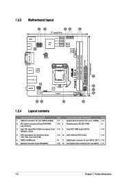
... (10-1 pin USB78, USB56) 1-17 7. System panel connector (10-1 pin F_PANEL) 1-13 2. ATX power connectors (24-pin EATXPWR, 1-13 8. Clear RTC RAM (3-pin CLRTC) 1-10 SATA3G_1/2/3/4) 4. CPU and chassis fan connectors (4-pin CPU_FAN, 4-pin CHA_FAN) 5. Intel® LGA1155 CPU socket 1-13 1-4 11. 1.2.3 Motherboard... ASM 1042 LGA1155 LAN1_USB3_12 AUDIO RTL 8111F AAFP VIA VT1708S EPU SPDIF_OUT PCIEX16 12 11 10 P8H61-I R2.0 2 SPEAKER F_PANEL 6 7 SB_PWR DRCT 8 CLRTC 9 1.2.4 Layout contents Connectors/Jumpers/Slots/LED Page Connectors/Jumpers/Slots/LED Page 1.
... (10-1 pin USB78, USB56) 1-17 7. System panel connector (10-1 pin F_PANEL) 1-13 2. ATX power connectors (24-pin EATXPWR, 1-13 8. Clear RTC RAM (3-pin CLRTC) 1-10 SATA3G_1/2/3/4) 4. CPU and chassis fan connectors (4-pin CPU_FAN, 4-pin CHA_FAN) 5. Intel® LGA1155 CPU socket 1-13 1-4 11. 1.2.3 Motherboard... ASM 1042 LGA1155 LAN1_USB3_12 AUDIO RTL 8111F AAFP VIA VT1708S EPU SPDIF_OUT PCIEX16 12 11 10 P8H61-I R2.0 2 SPEAKER F_PANEL 6 7 SB_PWR DRCT 8 CLRTC 9 1.2.4 Layout contents Connectors/Jumpers/Slots/LED Page Connectors/Jumpers/Slots/LED Page 1.
P8H61-I R2.0 User's Manual
Page 24
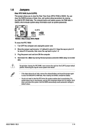
.... Plug the power cord and turn ON the computer. 4. The onboard button cell battery powers the RAM data in CMOS. CLRTC 12 23 P8H61-I R2.0 Normal (Default) Clear RTC P8H61-I R2.0 1-14 ASUS P8H61-I R2.0 Clear RTC RAM To erase the RTC RAM: 1. Except when clearing the RTC RAM, never remove the cap from pins 1-2 (default) to clear the CMOS RTC...
.... Plug the power cord and turn ON the computer. 4. The onboard button cell battery powers the RAM data in CMOS. CLRTC 12 23 P8H61-I R2.0 Normal (Default) Clear RTC P8H61-I R2.0 1-14 ASUS P8H61-I R2.0 Clear RTC RAM To erase the RTC RAM: 1. Except when clearing the RTC RAM, never remove the cap from pins 1-2 (default) to clear the CMOS RTC...
P8H61-I R2.0 User's Manual
Page 38
... to turn the system off then back on the system chassis. • Press the power button to erase the RTC RAM. • The BIOS setup program does not support bluetooth devices. 2-6 ASUS P8H61-I R2.0 Using the power button, reset button, or the ++ keys to force a running operating system to reboot can cause damage to...
... to turn the system off then back on the system chassis. • Press the power button to erase the RTC RAM. • The BIOS setup program does not support bluetooth devices. 2-6 ASUS P8H61-I R2.0 Using the power button, reset button, or the ++ keys to force a running operating system to reboot can cause damage to...
P8H61-I R2.0 User's Manual
Page 42
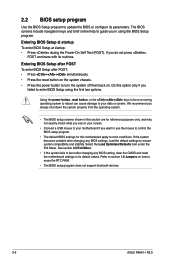
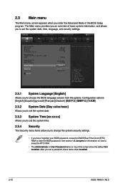
...allow you to change the system security settings. • If you have forgotten your BIOS password, erase the CMOS Real Time Clock (RTC) RAM to clear the BIOS password. See section 1.6 Jumpers for information on how to choose the BIOS language version from the options. Configuration options: ... RTC RAM. • The Administrator or User Password items on top of the BIOS Setup program. After you set a password, these items show the default Not Installed. 2.3 Main menu The Main menu screen appears when you enter the Advanced Mode of the screen show Installed. 2-10 ASUS P8H61-I R2.0
...allow you to change the system security settings. • If you have forgotten your BIOS password, erase the CMOS Real Time Clock (RTC) RAM to clear the BIOS password. See section 1.6 Jumpers for information on how to choose the BIOS language version from the options. Configuration options: ... RTC RAM. • The Administrator or User Password items on top of the BIOS Setup program. After you set a password, these items show the default Not Installed. 2.3 Main menu The Main menu screen appears when you enter the Advanced Mode of the screen show Installed. 2-10 ASUS P8H61-I R2.0


