
P8H61-I R2.0 User's Manual
Page 1
Motherboard P8H61-I R2.0
Motherboard P8H61-I R2.0
P8H61-I R2.0 User's Manual
Page 3
Contents Safety information vi About this guide vi P8H61-I R2.0 specifications summary viii Chapter 1 Product introduction 1.1 Before you proceed 1-1 1.2 Motherboard overview 1-2 1.2.1 Placement direction 1-2 1.2.2 Screw holes 1-2 1.2.3 Motherboard layout 1-3 1.2.4 Layout contents 1-3 1.3 Central Processing Unit (CPU 1-4 1.4 System memory 1-4 1.4.1 Overview 1-4 1.4.2 ...information 1-22 Chapter 2 BIOS information 2.1 Managing and updating your BIOS 2-1 2.1.1 ASUS Update utility 2-1 2.1.2 ASUS EZ Flash 2 2-2 2.1.3 ASUS CrashFree BIOS 3 utility 2-3 2.1.4 ASUS BIOS Updater 2-4 iii
Contents Safety information vi About this guide vi P8H61-I R2.0 specifications summary viii Chapter 1 Product introduction 1.1 Before you proceed 1-1 1.2 Motherboard overview 1-2 1.2.1 Placement direction 1-2 1.2.2 Screw holes 1-2 1.2.3 Motherboard layout 1-3 1.2.4 Layout contents 1-3 1.3 Central Processing Unit (CPU 1-4 1.4 System memory 1-4 1.4.1 Overview 1-4 1.4.2 ...information 1-22 Chapter 2 BIOS information 2.1 Managing and updating your BIOS 2-1 2.1.1 ASUS Update utility 2-1 2.1.2 ASUS EZ Flash 2 2-2 2.1.3 ASUS CrashFree BIOS 3 utility 2-3 2.1.4 ASUS BIOS Updater 2-4 iii

P8H61-I R2.0 User's Manual
Page 6
...• Ensure that your power supply is set to change system settings through the BIOS Setup menus. Detailed descriptions of the motherboard and the new technology it by yourself. vi How this guide This user guide contains the information you are connected. If ...• Chapter 1: Product introduction This chapter describes the features of the BIOS parameters are not damaged. Operation safety • Before installing the motherboard and adding devices on a stable surface. • If you encounter technical problems with the package. • Before using the product, ensure...
...• Ensure that your power supply is set to change system settings through the BIOS Setup menus. Detailed descriptions of the motherboard and the new technology it by yourself. vi How this guide This user guide contains the information you are connected. If ...• Chapter 1: Product introduction This chapter describes the features of the BIOS parameters are not damaged. Operation safety • Before installing the motherboard and adding devices on a stable surface. • If you encounter technical problems with the package. • Before using the product, ensure...
P8H61-I R2.0 User's Manual
Page 11
... your retailer. 1.1 Before you proceed Take note of the following precautions before you install motherboard components or change any motherboard settings. • Unplug the power cord from the power supply. Refer to page ix for buying an ASUS® P8H61-I R2.0 Onboard LED 1-1 Chapter 1: Product introduction Failure to do so may cause severe damage to...
... your retailer. 1.1 Before you proceed Take note of the following precautions before you install motherboard components or change any motherboard settings. • Unplug the power cord from the power supply. Refer to page ix for buying an ASUS® P8H61-I R2.0 Onboard LED 1-1 Chapter 1: Product introduction Failure to do so may cause severe damage to...
P8H61-I R2.0 User's Manual
Page 12
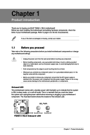
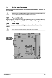
... overtighten the screws! The edge with external ports goes to the rear part of the chassis P8H61-I R2.0 ASUS P8H61-I R2.0 1-2 1.2 Motherboard overview Before you physical injury and damage motherboard components. 1.2.1 Placement direction When installing the motherboard, place it into the holes indicated by circles to secure the motherboard to the chassis. Failure to do so can damage the...
... overtighten the screws! The edge with external ports goes to the rear part of the chassis P8H61-I R2.0 ASUS P8H61-I R2.0 1-2 1.2 Motherboard overview Before you physical injury and damage motherboard components. 1.2.1 Placement direction When installing the motherboard, place it into the holes indicated by circles to secure the motherboard to the chassis. Failure to do so can damage the...
P8H61-I R2.0 User's Manual
Page 13
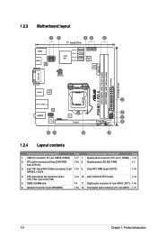
...System panel connector (10-1 pin F_PANEL) 1-13 2. Clear RTC RAM (3-pin CLRTC) 1-10 SATA3G_1/2/3/4) 4. DDR3 U-DIMM slots 6. 1.2.3 Motherboard layout 12 34 5 17.1cm(6.75in) KBMS HDMI ASM 1442 USB78 USB56 Intel® H61 SATA3G_1 SATA3G_2 SATA3G_3 SATA3G_4 CPU_FAN CHA_FAN Super I/O ... (64bit, 240-pin module) DVI_VGA USB12 ASM 1042 LGA1155 LAN1_USB3_12 AUDIO RTL 8111F AAFP VIA VT1708S EPU SPDIF_OUT PCIEX16 12 11 10 P8H61-I R2.0 2 SPEAKER F_PANEL 6 7 SB_PWR DRCT 8 CLRTC 9 1.2.4 Layout contents Connectors/Jumpers/Slots/LED Page Connectors/Jumpers/Slots/LED Page...
...System panel connector (10-1 pin F_PANEL) 1-13 2. Clear RTC RAM (3-pin CLRTC) 1-10 SATA3G_1/2/3/4) 4. DDR3 U-DIMM slots 6. 1.2.3 Motherboard layout 12 34 5 17.1cm(6.75in) KBMS HDMI ASM 1442 USB78 USB56 Intel® H61 SATA3G_1 SATA3G_2 SATA3G_3 SATA3G_4 CPU_FAN CHA_FAN Super I/O ... (64bit, 240-pin module) DVI_VGA USB12 ASM 1042 LGA1155 LAN1_USB3_12 AUDIO RTL 8111F AAFP VIA VT1708S EPU SPDIF_OUT PCIEX16 12 11 10 P8H61-I R2.0 2 SPEAKER F_PANEL 6 7 SB_PWR DRCT 8 CLRTC 9 1.2.4 Layout contents Connectors/Jumpers/Slots/LED Page Connectors/Jumpers/Slots/LED Page...
P8H61-I R2.0 User's Manual
Page 14
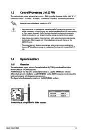
... of the PnP cap. 1.4 System memory 1.4.1 Overview The motherboard comes with less power consumption. ASUS will process Return Merchandise Authorization (RMA) requests only if the motherboard comes with the cap on the LGA1155 socket. •...motherboard, ensure that the PnP cap is missing, or if you see any damage to the socket contacts resulting from incorrect CPU installation/removal, or misplacement/loss/incorrect removal of the DDR3 DIMM sockets: DIMMA1 DIMMB1 Channel Channel A Channel B Sockets DIMM_A1 DIMM_B1 P8H61-I R2.0 P8H61-I R2.0 240-pin DDR3 DIMM sockets ASUS P8H61-I R2...
... of the PnP cap. 1.4 System memory 1.4.1 Overview The motherboard comes with less power consumption. ASUS will process Return Merchandise Authorization (RMA) requests only if the motherboard comes with the cap on the LGA1155 socket. •...motherboard, ensure that the PnP cap is missing, or if you see any damage to the socket contacts resulting from incorrect CPU installation/removal, or misplacement/loss/incorrect removal of the DDR3 DIMM sockets: DIMMA1 DIMMB1 Channel Channel A Channel B Sockets DIMM_A1 DIMM_B1 P8H61-I R2.0 P8H61-I R2.0 240-pin DDR3 DIMM sockets ASUS P8H61-I R2...
P8H61-I R2.0 User's Manual
Page 15
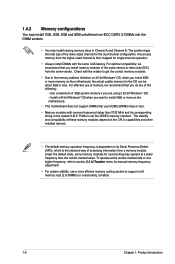
...• Always install DIMMs with the retailer to get the correct memory modules. • Due to install 4GB or more memory on the motherboard. • This motherboard does not support DIMMs that you install memory modules of the following: - For optimal compatibility, we recommend that use a more efficient memory cooling... memory if you want to the memory address limitation on 32-bit Windows® OS, when you install 4GB or more on the motherboard, the actual usable memory for the dual-channel configuration. The system maps the total size of the lower-sized channel for the OS ...
...• Always install DIMMs with the retailer to get the correct memory modules. • Due to install 4GB or more memory on the motherboard. • This motherboard does not support DIMMs that you install memory modules of the following: - For optimal compatibility, we recommend that use a more efficient memory cooling... memory if you want to the memory address limitation on 32-bit Windows® OS, when you install 4GB or more on the motherboard, the actual usable memory for the dual-channel configuration. The system maps the total size of the lower-sized channel for the OS ...
P8H61-I R2.0 User's Manual
Page 16
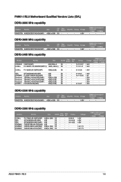
.../4GX(XMP) Size SS/ DS Chip Brand Chip NO. Timing DS DS DS DS DS DS - - 8-8-8-24 - 9-10-9-28 - 9-11-9-28 ---- P8H61-I R2.0 1-6 Timing Voltage 4GB(2 x 2GB) DS - - - 1.65V DIMM socket support (Optional) 1 DIMM 2 DIMMs • • DDR3-2600 MHz...7V 1.5V-1.7V DIMM socket support (Optional) 1 DIMM 2 DIMM · · · · · · · · · · ASUS P8H61-I R2.0 Motherboard Qualified Vendors Lists (QVL) DDR3-2666 MHz capability Vendors Part No. Timing Voltage 4GB(2 x 2GB) DS - - - 1.65V DIMM socket support (Optional) 1 DIMM 2 ...
.../4GX(XMP) Size SS/ DS Chip Brand Chip NO. Timing DS DS DS DS DS DS - - 8-8-8-24 - 9-10-9-28 - 9-11-9-28 ---- P8H61-I R2.0 1-6 Timing Voltage 4GB(2 x 2GB) DS - - - 1.65V DIMM socket support (Optional) 1 DIMM 2 DIMMs • • DDR3-2600 MHz...7V 1.5V-1.7V DIMM socket support (Optional) 1 DIMM 2 DIMM · · · · · · · · · · ASUS P8H61-I R2.0 Motherboard Qualified Vendors Lists (QVL) DDR3-2666 MHz capability Vendors Part No. Timing Voltage 4GB(2 x 2GB) DS - - - 1.65V DIMM socket support (Optional) 1 DIMM 2 ...
P8H61-I R2.0 User's Manual
Page 23
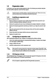
...removed earlier. 6. Failure to do not need to the chassis with PCI Express specifications. Remove the system unit cover (if your motherboard is supported by adjusting the software settings. 1. Align the card connector with it by Intel® 3rd generation processors. 1-13 ... install expansion cards. See Chapter 2 for the card. 2. 1.5 Expansion slots In the future, you may cause you physical injury and damage motherboard components. 1.5.1 Installing an expansion card To install an expansion card: 1. Assign an IRQ to use . 4. Remove the bracket opposite the slot...
...removed earlier. 6. Failure to do not need to the chassis with PCI Express specifications. Remove the system unit cover (if your motherboard is supported by adjusting the software settings. 1. Align the card connector with it by Intel® 3rd generation processors. 1-13 ... install expansion cards. See Chapter 2 for the card. 2. 1.5 Expansion slots In the future, you may cause you physical injury and damage motherboard components. 1.5.1 Installing an expansion card To install an expansion card: 1. Assign an IRQ to use . 4. Remove the bracket opposite the slot...
P8H61-I R2.0 User's Manual
Page 28
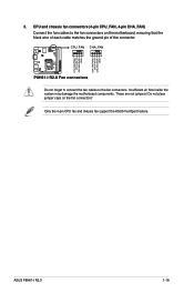
...jumpers! Only the 4-pin CPU fan and chassis fan support the ASUS FanXpert feature. P8H61-I R2.0 1-18 Do not place jumper caps on the motherboard, ensuring that the black wire of each cable matches the ground pin of the connector. ASUS P8H61-I R2.0 CPU FAN PWM CPU FAN IN CPU FAN PWR GND CHA ...FAN PWM CPU FAN IN CHA FAN PWR GND 3. Insufficient air flow inside the system may damage the motherboard components. CPU_FAN CHA_FAN P8H61-I R2.0 Fan connectors Do not forget to connect ...
...jumpers! Only the 4-pin CPU fan and chassis fan support the ASUS FanXpert feature. P8H61-I R2.0 1-18 Do not place jumper caps on the motherboard, ensuring that the black wire of each cable matches the ground pin of the connector. ASUS P8H61-I R2.0 CPU FAN PWM CPU FAN IN CPU FAN PWR GND CHA ...FAN PWM CPU FAN IN CHA FAN PWR GND 3. Insufficient air flow inside the system may damage the motherboard components. CPU_FAN CHA_FAN P8H61-I R2.0 Fan connectors Do not forget to connect ...
P8H61-I R2.0 User's Manual
Page 31
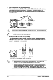
...port. 7. P8H61-I R2.0 USB78 PIN 1 USB+5V USB_P7USB_P7+ GND USB+5V USB_P8USB_P8+ GND NC USB56 PIN 1 USB+5V USB_P5USB_P5+ GND USB+5V USB_P6USB_P6+ GND NC P8H61-I /O module that you connect a high-definition front panel audio module to this connector to avail of the motherboard's high-definition ...AAFP PIN 1 MIC2 MICPWR Line out_R NC Line out_L PORT1 L PORT1 R PORT2 R SENSE_SEND PORT2 L P8H61-I R2.0 HD-audio-compliant Legacy AC'97 pin definition compliant definition P8H61-I /O module cable to [AC97]. This USB connector complies with USB 2.0 specifications and supports up to 480...
...port. 7. P8H61-I R2.0 USB78 PIN 1 USB+5V USB_P7USB_P7+ GND USB+5V USB_P8USB_P8+ GND NC USB56 PIN 1 USB+5V USB_P5USB_P5+ GND USB+5V USB_P6USB_P6+ GND NC P8H61-I /O module that you connect a high-definition front panel audio module to this connector to avail of the motherboard's high-definition ...AAFP PIN 1 MIC2 MICPWR Line out_R NC Line out_L PORT1 L PORT1 R PORT2 R SENSE_SEND PORT2 L P8H61-I R2.0 HD-audio-compliant Legacy AC'97 pin definition compliant definition P8H61-I /O module cable to [AC97]. This USB connector complies with USB 2.0 specifications and supports up to 480...
P8H61-I R2.0 User's Manual
Page 32
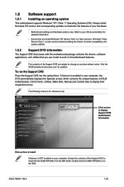
...that you can install to display their respective menus. The contents of ASUS motherboards. The following screen is enabled in your hardware. • Motherboard settings and hardware options vary. ASUS P8H61-I R2.0 1-22 Visit the ASUS website at any time without notice. If Autorun is for updates. Double...-click the ASSETUP.EXE to change at www.asus.com for reference only. To run ...
...that you can install to display their respective menus. The contents of ASUS motherboards. The following screen is enabled in your hardware. • Motherboard settings and hardware options vary. ASUS P8H61-I R2.0 1-22 Visit the ASUS website at any time without notice. If Autorun is for updates. Double...-click the ASSETUP.EXE to change at www.asus.com for reference only. To run ...
P8H61-I R2.0 User's Manual
Page 33
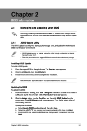
... Internet Service Provider (ISP). • This utility is a utility that comes with the motherboard package. Select the ASUS FTP site nearest you to complete the installation. c. Copy the original motherboard BIOS using this utility. Chapter 2 BIOS information 2.1 Managing and updating your BIOS Save a... copy of the original motherboard BIOS file to a USB flash disk in case you need to manage, save, and update the motherboard BIOS in a Windows® environment. • ASUS Update requires an Internet connection either of the following methods: ...
... Internet Service Provider (ISP). • This utility is a utility that comes with the motherboard package. Select the ASUS FTP site nearest you to complete the installation. c. Copy the original motherboard BIOS using this utility. Chapter 2 BIOS information 2.1 Managing and updating your BIOS Save a... copy of the original motherboard BIOS file to a USB flash disk in case you need to manage, save, and update the motherboard BIOS in a Windows® environment. • ASUS Update requires an Internet connection either of the following methods: ...
P8H61-I R2.0 User's Manual
Page 35
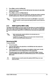
...the BIOS file to load default BIOS values. When found, the utility reads the BIOS file and enters ASUS EZ Flash 2 utility automatically. 4. Doing so can restore a corrupted BIOS file using the motherboard support DVD or a USB flash drive that contains the updated BIOS file. • Before using FAT 16... 3 is done. • This function supports USB flash disks formatted using this utility, rename the BIOS file in the removable device into P8H61-I-R2-ASUS-0306.ROM. • The BIOS file in the support DVD may not be the latest version. Press the Up/Down arrow keys to find...
...the BIOS file to load default BIOS values. When found, the utility reads the BIOS file and enters ASUS EZ Flash 2 utility automatically. 4. Doing so can restore a corrupted BIOS file using the motherboard support DVD or a USB flash drive that contains the updated BIOS file. • Before using FAT 16... 3 is done. • This function supports USB flash disks formatted using this utility, rename the BIOS file in the removable device into P8H61-I-R2-ASUS-0306.ROM. • The BIOS file in the support DVD may not be the latest version. Press the Up/Down arrow keys to find...
P8H61-I R2.0 User's Manual
Page 36
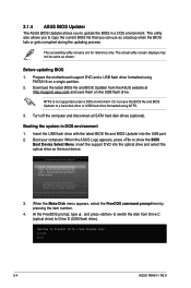
...the system in a DOS environment. When the Make Disk menu appears, select the FreeDOS command prompt item by pressing the item number. 4. C:\>d: D:\> 2-4 ASUS P8H61-I R2.0 NTFS is not supported under a DOS environment. Welcome to a hard disk drive or USB flash drive formatted using NTFS. 3. Before updating BIOS 1. Insert... copy the current BIOS file that you can use as shown. The succeeding utility screens are for reference only. Prepare the motherboard support DVD and a USB flash drive formatted using defaults 3. This utility also allows you to boot using FAT32/16 on the ...
...the system in a DOS environment. When the Make Disk menu appears, select the FreeDOS command prompt item by pressing the item number. 4. C:\>d: D:\> 2-4 ASUS P8H61-I R2.0 NTFS is not supported under a DOS environment. Welcome to a hard disk drive or USB flash drive formatted using NTFS. 3. Before updating BIOS 1. Insert... copy the current BIOS file that you can use as shown. The succeeding utility screens are for reference only. Prepare the motherboard support DVD and a USB flash drive formatted using defaults 3. This utility also allows you to boot using FAT32/16 on the ...
P8H61-I R2.0 User's Manual
Page 38
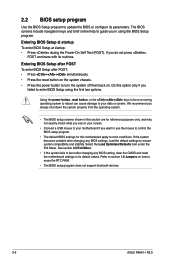
...On Self Test (POST). Entering BIOS Setup after POST To enter BIOS Setup after changing any BIOS setting, clear the CMOS and reset the motherboard settings to update the BIOS or configure its routines. Using the power button, reset button, or the ++ keys to force a running ... use the mouse to control the BIOS setup program. • The default BIOS settings for this motherboard apply to erase the RTC RAM. • The BIOS setup program does not support bluetooth devices. 2-6 ASUS P8H61-I R2.0 If the system becomes unstable after POST: • Press ++ simultaneously. • Press the...
...On Self Test (POST). Entering BIOS Setup after POST To enter BIOS Setup after changing any BIOS setting, clear the CMOS and reset the motherboard settings to update the BIOS or configure its routines. Using the power button, reset button, or the ++ keys to force a running ... use the mouse to control the BIOS setup program. • The default BIOS settings for this motherboard apply to erase the RTC RAM. • The BIOS setup program does not support bluetooth devices. 2-6 ASUS P8H61-I R2.0 If the system becomes unstable after POST: • Press ++ simultaneously. • Press the...
P8H61-I R2.0 User's Manual
Page 39
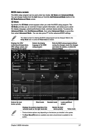
To access the Advanced Mode, click Exit/Advanced Mode, then select Advanced Mode or press Esc, then select Advanced Mode. Displays the CPU/ motherboard temperature, CPU voltage output, and CPU/chassis fan speed Selects the display language of the BIOS setup program Exits the BIOS setup program without saving ...
To access the Advanced Mode, click Exit/Advanced Mode, then select Advanced Mode or press Esc, then select Advanced Mode. Displays the CPU/ motherboard temperature, CPU voltage output, and CPU/chassis fan speed Selects the display language of the BIOS setup program Exits the BIOS setup program without saving ...
P8H61-I R2.0 User's Manual
Page 44
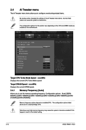
... options: [Auto] [DDR3800MHz] [DDR3-1066MHz] [DDR3-1333MHz] [DDR3-1600MHz] [DDR3-1866MHz] [DDR32133MHz] [DDR3-2400MHz] Memory frequency options depend on the motherboard. If this section vary depending on the CPU and DIMM model you installed on installed CPU. 2.4 Ai Tweaker menu The Ai Tweaker menu items allow... the settings of the Ai Tweaker menu items. Incorrect field values can cause the system to the default setting. 2-12 ASUS P8H61-I R2.0 The configuration options for a Sandy Bridge CPU. Target CPU Turbo-Mode Speed : xxxxMHz Displays the current CPU Turbo-Mode speed.
... options: [Auto] [DDR3800MHz] [DDR3-1066MHz] [DDR3-1333MHz] [DDR3-1600MHz] [DDR3-1866MHz] [DDR32133MHz] [DDR3-2400MHz] Memory frequency options depend on the motherboard. If this section vary depending on the CPU and DIMM model you installed on installed CPU. 2.4 Ai Tweaker menu The Ai Tweaker menu items allow... the settings of the Ai Tweaker menu items. Incorrect field values can cause the system to the default setting. 2-12 ASUS P8H61-I R2.0 The configuration options for a Sandy Bridge CPU. Target CPU Turbo-Mode Speed : xxxxMHz Displays the current CPU Turbo-Mode speed.

P8H61-I R2.0 User's Manual
Page 55
...;[x�x�x��º�C�/x�x�x��º�F�] The onboard hardware monitor automatically detects and displays the CPU and motherboard temperatures. Select Ignore if you to change the fan settings. Chapter 2: BIOS information 2-23 2.6 Monitor menu The Monitor menu displays the system temperature/power status... and chassis fan speeds in rotations per minute (RPM). Select Ignore if you do not wish to display the detected speed. Scroll down to the motherboard, the field shows N/A.
...;[x�x�x��º�C�/x�x�x��º�F�] The onboard hardware monitor automatically detects and displays the CPU and motherboard temperatures. Select Ignore if you to change the fan settings. Chapter 2: BIOS information 2-23 2.6 Monitor menu The Monitor menu displays the system temperature/power status... and chassis fan speeds in rotations per minute (RPM). Select Ignore if you do not wish to display the detected speed. Scroll down to the motherboard, the field shows N/A.


