
User Guide
Page 1
P8B-X Motherboard
P8B-X Motherboard
User Guide
Page 3
... to find more information ix Conventions used in this guide x Typography x P8B-X specifications summary xi Chapter 1: Product introduction 1.1 Welcome 1-3 1.2 Package contents 1-3 1.3 Serial number label 1-4 1.4 Special features 1-4 1.4.1 Product highlights 1-4 1.4.2 Innovative ASUS features 1-6 Chapter 2: Hardware information 2.1 Before you proceed 2-3 2.2 Motherboard overview 2-5 2.2.1 Placement direction 2-5 2.2.2 Screw holes 2-5 2.2.3 Motherboard layout 2-6 2.2.4 Layout contents 2-8 2.3 Central Processing Unit (CPU 2-10 2.3.1 Installing the...
... to find more information ix Conventions used in this guide x Typography x P8B-X specifications summary xi Chapter 1: Product introduction 1.1 Welcome 1-3 1.2 Package contents 1-3 1.3 Serial number label 1-4 1.4 Special features 1-4 1.4.1 Product highlights 1-4 1.4.2 Innovative ASUS features 1-6 Chapter 2: Hardware information 2.1 Before you proceed 2-3 2.2 Motherboard overview 2-5 2.2.1 Placement direction 2-5 2.2.2 Screw holes 2-5 2.2.3 Motherboard layout 2-6 2.2.4 Layout contents 2-8 2.3 Central Processing Unit (CPU 2-10 2.3.1 Installing the...
User Guide
Page 8
...and staples away from connectors, slots, sockets and circuitry. • Avoid dust, humidity, and temperature extremes. DO NOT throw the motherboard in municipal waste. Safety information Electrical safety • To prevent electrical shock hazard, disconnect the power cable from the electrical outlet before ...relocating the system. • When adding or removing devices to or from the motherboard, ensure that all power cables are unplugged. • Seek professional assistance before using an adapter or extension cord. Operation safety ...
...and staples away from connectors, slots, sockets and circuitry. • Avoid dust, humidity, and temperature extremes. DO NOT throw the motherboard in municipal waste. Safety information Electrical safety • To prevent electrical shock hazard, disconnect the power cable from the electrical outlet before ...relocating the system. • When adding or removing devices to or from the motherboard, ensure that all power cables are unplugged. • Seek professional assistance before using an adapter or extension cord. Operation safety ...
User Guide
Page 9
... includes additional information that you may refer to when configuring the motherboard. Detailed descriptions of the BIOS parameters are not part of the switches, jumpers, and connectors on ASUS hardware and software products. Refer to perform when installing system components.... Optional documentation Your product package may have to the ASUS contact information. 2. ASUS websites The ASUS website provides updated information on the motherboard. • Chapter 3: Powering up This chapter describes the power up , creating, and ...
... includes additional information that you may refer to when configuring the motherboard. Detailed descriptions of the BIOS parameters are not part of the switches, jumpers, and connectors on ASUS hardware and software products. Refer to perform when installing system components.... Optional documentation Your product package may have to the ASUS contact information. 2. ASUS websites The ASUS website provides updated information on the motherboard. • Chapter 3: Powering up This chapter describes the power up , creating, and ...

User Guide
Page 13
This chapter describes the motherboard introPdruoc1dtuiocnt features and the new technologies it supports.
This chapter describes the motherboard introPdruoc1dtuiocnt features and the new technologies it supports.
User Guide
Page 15
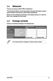
1.1 Welcome! Standard Gift Box Pack 6 1 1 1 1 1pc per carton Standard Bulk Pack -1 1 1 1 10pcs per carton If any of ASUS quality motherboards! ASUS P8B-X 1-3 Thank you start installing the motherboard, and hardware devices on it another standout in your package with the list below. 1.2 Package contents Check your retailer. Before you for LGA1155 Application CD ...
1.1 Welcome! Standard Gift Box Pack 6 1 1 1 1 1pc per carton Standard Bulk Pack -1 1 1 1 10pcs per carton If any of ASUS quality motherboards! ASUS P8B-X 1-3 Thank you start installing the motherboard, and hardware devices on it another standout in your package with the list below. 1.2 Package contents Check your retailer. Before you for LGA1155 Application CD ...
User Guide
Page 16
The Intel® EM64T feature allows your problems. P8B-X xxS2xxxxxxxx Made in China 合格 1.4 Special features 1.4.1 Product highlights Latest processor technology This motherboard supports the latest Intel® Xeon® E3-1200/Core™ i3-2100 processors in the world.... of both multi-threaded and single-threaded workloads. 1.3 Serial number label Before requesting support from the ASUS Technical Support team, you must take note of the motherboard's serial number containing 12 characters xxS2xxxxxxxx shown as the figure below power, temperature and current limits. ...
The Intel® EM64T feature allows your problems. P8B-X xxS2xxxxxxxx Made in China 合格 1.4 Special features 1.4.1 Product highlights Latest processor technology This motherboard supports the latest Intel® Xeon® E3-1200/Core™ i3-2100 processors in the world.... of both multi-threaded and single-threaded workloads. 1.3 Serial number label Before requesting support from the ASUS Technical Support team, you must take note of the motherboard's serial number containing 12 characters xxS2xxxxxxxx shown as the figure below power, temperature and current limits. ...
User Guide
Page 17
PCIe 2.0 This motherboard supports the latest PCIe 2.0 device for DDR3. ASUS P8B-X 1-5 This voltage reduction limits the power consumption and heat generation of new features, including Native Command Queuing (NCQ), Power Management (PM) Implementation ...Technology (EIST) intelligently manages the CPU resources by automatically adjusting the CPU voltage and core frequency depending on USB 2.0. Serial ATA II technology The motherboard supports the Serial ATA II 3 Gb/s technology through the Serial ATA interface and Intel® C202 chipset. The onboard Intel® 82574L Gigabit...
PCIe 2.0 This motherboard supports the latest PCIe 2.0 device for DDR3. ASUS P8B-X 1-5 This voltage reduction limits the power consumption and heat generation of new features, including Native Command Queuing (NCQ), Power Management (PM) Implementation ...Technology (EIST) intelligently manages the CPU resources by automatically adjusting the CPU voltage and core frequency depending on USB 2.0. Serial ATA II technology The motherboard supports the Serial ATA II 3 Gb/s technology through the Serial ATA interface and Intel® C202 chipset. The onboard Intel® 82574L Gigabit...
User Guide
Page 19
Chapter 2: 2 Hardware information It includes description of the jumpers and connectors on the motherboard. This chapter lists the hardware setup procedures that you have to perform when installing system components.
Chapter 2: 2 Hardware information It includes description of the jumpers and connectors on the motherboard. This chapter lists the hardware setup procedures that you have to perform when installing system components.
User Guide
Page 20
Chapter summary 2 2.1 Before you proceed 2-3 2.2 Motherboard overview 2-5 2.3 Central Processing Unit (CPU 2-10 2.4 System memory 2-16 2.5 Expansion slots 2-18 2.6 Jumpers 2-22 2.7 Connectors 2-26 ASUS P8B-X
Chapter summary 2 2.1 Before you proceed 2-3 2.2 Motherboard overview 2-5 2.3 Central Processing Unit (CPU 2-10 2.4 System memory 2-16 2.5 Expansion slots 2-18 2.6 Jumpers 2-22 2.7 Connectors 2-26 ASUS P8B-X
User Guide
Page 21
2.1 Before you proceed Take note of the following precautions before you install motherboard components or change any motherboard settings. • Unplug the power cord from the power supply. Failure to do so may cause severe damage to avoid touching the ICs on them. &#..., such as the power supply case, before handling components to avoid damaging them due to static electricity. • Hold components by the edges to the motherboard, peripherals, and/or components. ASUS P8B-X 2-3
2.1 Before you proceed Take note of the following precautions before you install motherboard components or change any motherboard settings. • Unplug the power cord from the power supply. Failure to do so may cause severe damage to avoid touching the ICs on them. &#..., such as the power supply case, before handling components to avoid damaging them due to static electricity. • Hold components by the edges to the motherboard, peripherals, and/or components. ASUS P8B-X 2-3
User Guide
Page 22
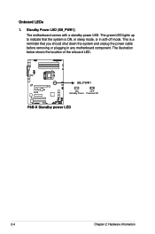
This is a reminder that the system is ON, in sleep mode, or in any motherboard component. The illustration below shows the location of the onboard LED. 2-4 Chapter 2: Hardware information The green LED lights up to indicate that you should shut down the system and unplug the power cable before removing or plugging in soft-off mode. Standby Power LED (SB_PWR1) The motherboard comes with a standby power LED. Onboard LEDs 1.
This is a reminder that the system is ON, in sleep mode, or in any motherboard component. The illustration below shows the location of the onboard LED. 2-4 Chapter 2: Hardware information The green LED lights up to indicate that you should shut down the system and unplug the power cable before removing or plugging in soft-off mode. Standby Power LED (SB_PWR1) The motherboard comes with a standby power LED. Onboard LEDs 1.
User Guide
Page 23
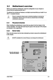
...goes to the rear part of the chassis ASUS P8B-X 2-5 Place this side towards the rear of the chassis as indicated in the image below. 2.2.2 Screw holes Place nine (9) screws into the holes indicated by circles to secure the motherboard to the chassis. Doing so can cause you... it in an ATX 1.1 compliant chassis. Failure to do so can damage the motherboard. Ensure to unplug the chassis power cord before installing or removing the motherboard. 2.2 Motherboard overview Before you install the motherboard, study the configuration of your chassis to ensure that you place it into the ...
...goes to the rear part of the chassis ASUS P8B-X 2-5 Place this side towards the rear of the chassis as indicated in the image below. 2.2.2 Screw holes Place nine (9) screws into the holes indicated by circles to secure the motherboard to the chassis. Doing so can cause you... it in an ATX 1.1 compliant chassis. Failure to do so can damage the motherboard. Ensure to unplug the chassis power cord before installing or removing the motherboard. 2.2 Motherboard overview Before you install the motherboard, study the configuration of your chassis to ensure that you place it into the ...
User Guide
Page 24
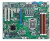
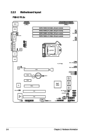
2.2.3 Motherboard layout P8B-X/ R1.0x 2-6 Chapter 2: Hardware information
2.2.3 Motherboard layout P8B-X/ R1.0x 2-6 Chapter 2: Hardware information
User Guide
Page 28
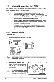
...immediately if the PnP cap is on the motherboard. Before installing the CPU, ensure that the PnP cap is missing, or if you and the load lever is shipment/transit-related. • Keep the cap after installing the motherboard. ASUS will process Return Merchandise Authorization (RMA) requests... only if the motherboard comes with your thumb (A), and then move it to the right (B) until it is released from incorrect...
...immediately if the PnP cap is on the motherboard. Before installing the CPU, ensure that the PnP cap is missing, or if you and the load lever is shipment/transit-related. • Keep the cap after installing the motherboard. ASUS will process Return Merchandise Authorization (RMA) requests... only if the motherboard comes with your thumb (A), and then move it to the right (B) until it is released from incorrect...
User Guide
Page 31
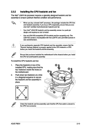
... ensure that you have installed the motherboard to the chassis before you buy a boxed Intel® processor, the package includes the CPU fan and heatsink assembly. Push down two fasteners at a time in a diagonal sequence to the CPU fan connector. ASUS P8B-X 2-13 Ensure that the Thermal ... the heatsink on top of the installed CPU, making sure that you buy a CPU separately, ensure that the four fasteners match the holes on the motherboard. B 2. To install the CPU heatsink and fan: 1. A B A A B 1 B A 1 Orient the heatsink and fan assembly such that the CPU fan ...
... ensure that you have installed the motherboard to the chassis before you buy a boxed Intel® processor, the package includes the CPU fan and heatsink assembly. Push down two fasteners at a time in a diagonal sequence to the CPU fan connector. ASUS P8B-X 2-13 Ensure that the Thermal ... the heatsink on top of the installed CPU, making sure that you buy a CPU separately, ensure that the four fasteners match the holes on the motherboard. B 2. To install the CPU heatsink and fan: 1. A B A A B 1 B A 1 Orient the heatsink and fan assembly such that the CPU fan ...
User Guide
Page 32
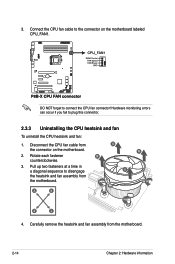
...information Carefully remove the heatsink and fan assembly from the connector on the motherboard labeled CPU_FAN1. Connect the CPU fan cable to connect the CPU fan connector! DO NOT forget to the connector on the motherboard. 2. Hardware monitoring errors can occur if you fail to disengage the ...heatsink and fan assembly from the motherboard. Pull up two fasteners at a time in a diagonal sequence to plug this connector....
...information Carefully remove the heatsink and fan assembly from the connector on the motherboard labeled CPU_FAN1. Connect the CPU fan cable to connect the CPU fan connector! DO NOT forget to the connector on the motherboard. 2. Hardware monitoring errors can occur if you fail to disengage the ...heatsink and fan assembly from the motherboard. Pull up two fasteners at a time in a diagonal sequence to plug this connector....

User Guide
Page 33
... in a diagonal sequence. Ensure that you have applied the thermal interface material to the top of the motherboard, matching the standoffs to the back of the CPU before installing the heatsink and fan. 1. ASUS P8B-X 2-15 Peel off the sticker on the heatsink metal plate and affix the plate to the heatsink screw...
... in a diagonal sequence. Ensure that you have applied the thermal interface material to the top of the motherboard, matching the standoffs to the back of the CPU before installing the heatsink and fan. 1. ASUS P8B-X 2-15 Peel off the sticker on the heatsink metal plate and affix the plate to the heatsink screw...
User Guide
Page 34
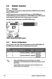
2.4 System memory 2.4.1 Overview The motherboard comes with less power consumption. A DDR3 module has the same physical dimensions as a DDR2 DIMM but is recommended that you obtain memory modules from the ... DIMMs with ECC DDR3 DIMMs into the DIMM sockets using the memory configurations in this section. For optimum compatibility, it is notched differently to the motherboard. 2-16 Chapter 2: Hardware information
2.4 System memory 2.4.1 Overview The motherboard comes with less power consumption. A DDR3 module has the same physical dimensions as a DDR2 DIMM but is recommended that you obtain memory modules from the ... DIMMs with ECC DDR3 DIMMs into the DIMM sockets using the memory configurations in this section. For optimum compatibility, it is notched differently to the motherboard. 2-16 Chapter 2: Hardware information
User Guide
Page 35
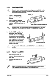
... or removing DIMMs or other system components. ASUS P8B-X 2-17 Failure to do so may cause severe damage to both ends of the DIMM simultaneously until the retaining 3 clips snap back into place, and the DIMM cannot be pushed in any further to both the motherboard and the components. 1. DO NOT force a DIMM...
... or removing DIMMs or other system components. ASUS P8B-X 2-17 Failure to do so may cause severe damage to both ends of the DIMM simultaneously until the retaining 3 clips snap back into place, and the DIMM cannot be pushed in any further to both the motherboard and the components. 1. DO NOT force a DIMM...


