User Guide
Page 15
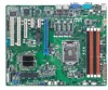
...! Thank you start installing the motherboard, and hardware devices on it another standout in your package with the list below. 1.2 Package contents Check your retailer. ASUS P8B-X 1-3 1.1 Welcome! The motherboard delivers a host of new features and latest technologies, making it , check the items in the long line of the above items is...
...! Thank you start installing the motherboard, and hardware devices on it another standout in your package with the list below. 1.2 Package contents Check your retailer. ASUS P8B-X 1-3 1.1 Welcome! The motherboard delivers a host of new features and latest technologies, making it , check the items in the long line of the above items is...
User Guide
Page 17
...devices. Serial ATA allows thinner, more flexible cables with dual Gigabit LAN controllers and ports which makes it an ideal memory solution. ASUS P8B-X 1-5 Enhanced Intel SpeedStep Technology (EIST) The Enhanced Intel SpeedStep Technology (EIST) intelligently manages the CPU resources by automatically adjusting ...for DDR3. This voltage reduction limits the power consumption and heat generation of server and workstation applications. DDR3 memory support The P8B-X supports UDIMM DDR3 memory that features data transfer rates of 1333/1066 MHZ to meet the higher bandwidth requirements of DDR3...
...devices. Serial ATA allows thinner, more flexible cables with dual Gigabit LAN controllers and ports which makes it an ideal memory solution. ASUS P8B-X 1-5 Enhanced Intel SpeedStep Technology (EIST) The Enhanced Intel SpeedStep Technology (EIST) intelligently manages the CPU resources by automatically adjusting ...for DDR3. This voltage reduction limits the power consumption and heat generation of server and workstation applications. DDR3 memory support The P8B-X supports UDIMM DDR3 memory that features data transfer rates of 1333/1066 MHZ to meet the higher bandwidth requirements of DDR3...
User Guide
Page 20
Chapter summary 2 2.1 Before you proceed 2-3 2.2 Motherboard overview 2-5 2.3 Central Processing Unit (CPU 2-10 2.4 System memory 2-16 2.5 Expansion slots 2-18 2.6 Jumpers 2-22 2.7 Connectors 2-26 ASUS P8B-X
Chapter summary 2 2.1 Before you proceed 2-3 2.2 Motherboard overview 2-5 2.3 Central Processing Unit (CPU 2-10 2.4 System memory 2-16 2.5 Expansion slots 2-18 2.6 Jumpers 2-22 2.7 Connectors 2-26 ASUS P8B-X
User Guide
Page 21
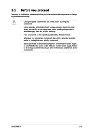
ASUS P8B-X 2-3 2.1 Before you proceed Take note of the following precautions before you install motherboard components or change any motherboard settings. • Unplug the power cord from ...
ASUS P8B-X 2-3 2.1 Before you proceed Take note of the following precautions before you install motherboard components or change any motherboard settings. • Unplug the power cord from ...
User Guide
Page 23
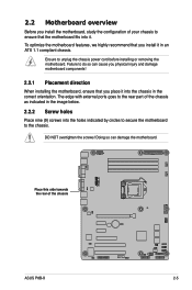
... unplug the chassis power cord before installing or removing the motherboard. DO NOT overtighten the screws! Place this side towards the rear of the chassis ASUS P8B-X 2-5 To optimize the motherboard features, we highly recommend that you install it in the image below. 2.2.2 Screw holes Place nine (9) screws into the chassis in...
... unplug the chassis power cord before installing or removing the motherboard. DO NOT overtighten the screws! Place this side towards the rear of the chassis ASUS P8B-X 2-5 To optimize the motherboard features, we highly recommend that you install it in the image below. 2.2.2 Screw holes Place nine (9) screws into the chassis in...
User Guide
Page 29
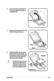
... socket alignment keys into the socket to prevent bending the connectors on the socket and damaging the CPU! Gold triangle mark Alignment keys CPU notches ASUS P8B-X 2-11 DO NOT force the CPU into the CPU notches. PnP cap Cap tab 5. Position the CPU over the socket, ensuring that the gold triangle...
... socket alignment keys into the socket to prevent bending the connectors on the socket and damaging the CPU! Gold triangle mark Alignment keys CPU notches ASUS P8B-X 2-11 DO NOT force the CPU into the CPU notches. PnP cap Cap tab 5. Position the CPU over the socket, ensuring that the gold triangle...
User Guide
Page 31
... heatsink and fan assembly, ensure that the Thermal Interface Material is properly applied to the CPU fan connector. To install the CPU heatsink and fan: 1. B 2. ASUS P8B-X 2-13
... heatsink and fan assembly, ensure that the Thermal Interface Material is properly applied to the CPU fan connector. To install the CPU heatsink and fan: 1. B 2. ASUS P8B-X 2-13

User Guide
Page 33
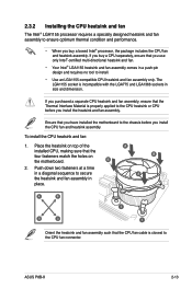
ASUS P8B-X 2-15 Ensure that you have applied the thermal interface material to tighten the four heatsink screws in a diagonal sequence. 2.3.4 Installing the CPU heatsink in rack ...
ASUS P8B-X 2-15 Ensure that you have applied the thermal interface material to tighten the four heatsink screws in a diagonal sequence. 2.3.4 Installing the CPU heatsink in rack ...
User Guide
Page 35
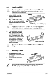
... notch on the DIMM matches the DIMM slot key on the socket such that it flips out with your fingers when pressing the retaining clips. ASUS P8B-X 2-17 Simultaneously press the retaining clips outward to unplug the power supply before adding or removing DIMMs or other system components. Unlock a DIMM socket by...
... notch on the DIMM matches the DIMM slot key on the socket such that it flips out with your fingers when pressing the retaining clips. ASUS P8B-X 2-17 Simultaneously press the retaining clips outward to unplug the power supply before adding or removing DIMMs or other system components. Unlock a DIMM socket by...
User Guide
Page 37
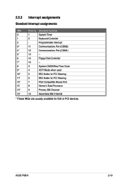
2.5.3 Interrupt assignments Standard Interrupt assignments IRQ Priority Standard function 0 1 System Timer 1 2 Keyboard Controller 2 - ASUS P8B-X 2-19 Programmable Interrupt 3* 11 Communications Port (COM2) 4* 12 Communications Port (COM1) 5* 13 -- 6 14 Floppy Disk Controller 7* 15 -- 8 3 System CMOS/Real Time Clock 9* 4 ACPI Mode when ...
2.5.3 Interrupt assignments Standard Interrupt assignments IRQ Priority Standard function 0 1 System Timer 1 2 Keyboard Controller 2 - ASUS P8B-X 2-19 Programmable Interrupt 3* 11 Communications Port (COM2) 4* 12 Communications Port (COM1) 5* 13 -- 6 14 Floppy Disk Controller 7* 15 -- 8 3 System CMOS/Real Time Clock 9* 4 ACPI Mode when ...
User Guide
Page 39
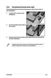
The photos above are for reference only. Connect the thermal sensor cable to monitor temperature. Place the other end of the thermal sensor cable to the device you would like to the connector. 3. Follow the main layout in previous section to locate the TR1 connector on your motherboard. ASUS P8B-X 2-21 2.5.8 Connecting the thermal sensor cable Follow the steps below to connect the thermal sensor cable to the connector on your motherboard. 1. Locate the TR1 connector on the motherboard. 2.
The photos above are for reference only. Connect the thermal sensor cable to monitor temperature. Place the other end of the thermal sensor cable to the device you would like to the connector. 3. Follow the main layout in previous section to locate the TR1 connector on your motherboard. ASUS P8B-X 2-21 2.5.8 Connecting the thermal sensor cable Follow the steps below to connect the thermal sensor cable to the connector on your motherboard. 1. Locate the TR1 connector on the motherboard. 2.
User Guide
Page 41
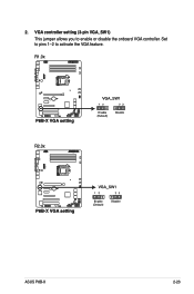
Set to pins 1-2 to enable or disable the onboard VGA controller. 2. R1.0x R2.0x ASUS P8B-X 2-23 VGA controller setting (3-pin VGA_SW1) This jumper allows you to activate the VGA feature.
Set to pins 1-2 to enable or disable the onboard VGA controller. 2. R1.0x R2.0x ASUS P8B-X 2-23 VGA controller setting (3-pin VGA_SW1) This jumper allows you to activate the VGA feature.
User Guide
Page 43
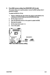
Force BIOS recovery setting (3-pin RECOVERY1) (R1.0x only) This jumper allows you to pins 2-3. 3. Insert the USB flash and turn on the system. Set the jumper to quickly update or recover the BIOS settings when it becomes corrupted. Turn on the system to pins 1-2. 6. Shut down the system. 5. Set the jumper back to update the BIOS. 4. To update the BIOS (for the motherboard (XXXXXX.ROM) and the BUPDATER.EXE utility. 2. ASUS P8B-X 2-25 Prepare a USB flash disk that contains the original or latest BIOS for R1.0x): 1. 5.
Force BIOS recovery setting (3-pin RECOVERY1) (R1.0x only) This jumper allows you to pins 2-3. 3. Insert the USB flash and turn on the system. Set the jumper to quickly update or recover the BIOS settings when it becomes corrupted. Turn on the system to pins 1-2. 6. Shut down the system. 5. Set the jumper back to update the BIOS. 4. To update the BIOS (for the motherboard (XXXXXX.ROM) and the BUPDATER.EXE utility. 2. ASUS P8B-X 2-25 Prepare a USB flash disk that contains the original or latest BIOS for R1.0x): 1. 5.
User Guide
Page 45
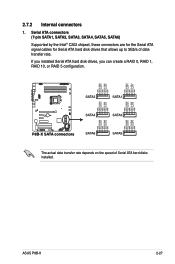
Serial ATA connectors (7-pin SATA1, SATA2, SATA3, SATA4, SATA5, SATA6) Supported by the Intel® C202 chipset, these connectors are for the Serial ATA signal cables for Serial ATA hard disk drives that allows up to 3Gb/s of Serial ATA hard disks installed. ASUS P8B-X 2-27 The actual data transfer rate depends on the speed of data transfer rate. If you installed Serial ATA hard disk drives, you can create a RAID 0, RAID 1, RAID 10, or RAID 5 configuration. 2.7.2 Internal connectors 1.
Serial ATA connectors (7-pin SATA1, SATA2, SATA3, SATA4, SATA5, SATA6) Supported by the Intel® C202 chipset, these connectors are for the Serial ATA signal cables for Serial ATA hard disk drives that allows up to 3Gb/s of Serial ATA hard disks installed. ASUS P8B-X 2-27 The actual data transfer rate depends on the speed of data transfer rate. If you installed Serial ATA hard disk drives, you can create a RAID 0, RAID 1, RAID 10, or RAID 5 configuration. 2.7.2 Internal connectors 1.

User Guide
Page 47
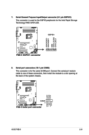
Connect the parallel port module cable to this connector and place the other end to the device, which you want to a slot opening at the back of the system chassis. Connect the thermal sensor cable to this connector, then install the module to monitor temperature. 5. Thermal sensor cable connectors (3-pin TR1) This connector is for temperature monitoring. ASUS P8B-X 2-29 Parallel port connector (26-1 pin LPT1) This connector is for a parallel port. 4.
Connect the parallel port module cable to this connector and place the other end to the device, which you want to a slot opening at the back of the system chassis. Connect the thermal sensor cable to this connector, then install the module to monitor temperature. 5. Thermal sensor cable connectors (3-pin TR1) This connector is for temperature monitoring. ASUS P8B-X 2-29 Parallel port connector (26-1 pin LPT1) This connector is for a parallel port. 4.
User Guide
Page 49
Serial port connectors (10-1 pin COM2) This connector is used for the SGPIO peripherals for the serial (COM) port. 7. Serial General Purpose Input/Output connector (6-1 pin SGPIO1) This connector is for the Intel Rapid Storage Technology RAID SATA LED. 8. Connect the serial port module cable to one of these connectors, then install the module to a slot opening at the back of the system chassis. ASUS P8B-X 2-31
Serial port connectors (10-1 pin COM2) This connector is used for the SGPIO peripherals for the serial (COM) port. 7. Serial General Purpose Input/Output connector (6-1 pin SGPIO1) This connector is for the Intel Rapid Storage Technology RAID SATA LED. 8. Connect the serial port module cable to one of these connectors, then install the module to a slot opening at the back of the system chassis. ASUS P8B-X 2-31
User Guide
Page 51
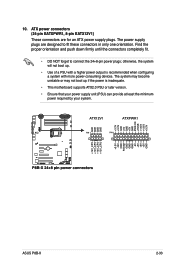
... supports ATX2.0 PSU or later version. • Ensure that your power supply unit (PSU) can provide at least the minimum power required by your system. ASUS P8B-X 2-33 Find the proper orientation and push down firmly until the connectors completely fit. • DO NOT forget to fit these connectors in only one...
... supports ATX2.0 PSU or later version. • Ensure that your power supply unit (PSU) can provide at least the minimum power required by your system. ASUS P8B-X 2-33 Find the proper orientation and push down firmly until the connectors completely fit. • DO NOT forget to fit these connectors in only one...

User Guide
Page 53
... function. 4. This button queries the state of the system locator. Chassis intrusion (4-1 pin CHASSIS) These leads are for the locator button on the front panel. ASUS P8B-X 2-35 Auxiliary panel connector (20-pin AUX_PANEL1) This connector is for chassis with intrusion sensor or microswitch. Locator LED (2-pin LOCATORLED1 and 2-pin LOCATORLED2) These...
... function. 4. This button queries the state of the system locator. Chassis intrusion (4-1 pin CHASSIS) These leads are for the locator button on the front panel. ASUS P8B-X 2-35 Auxiliary panel connector (20-pin AUX_PANEL1) This connector is for chassis with intrusion sensor or microswitch. Locator LED (2-pin LOCATORLED1 and 2-pin LOCATORLED2) These...
User Guide
Page 56
Chapter summary 3 3.1 Starting up for the first time 3-3 3.2 Powering off the computer 3-4 ASUS P8B-X
Chapter summary 3 3.1 Starting up for the first time 3-3 3.2 Powering off the computer 3-4 ASUS P8B-X
User Guide
Page 57
.... After making all switches are running, the BIOS beeps or additional messages appear on self-test or POST. External storage devices (starting with a surge protector. 5. ASUS P8B-X 3-3 Monitor b. Be sure that is equipped with the last device on the system front panel case lights up for assistance. 7. Connect the power cord to...
.... After making all switches are running, the BIOS beeps or additional messages appear on self-test or POST. External storage devices (starting with a surge protector. 5. ASUS P8B-X 3-3 Monitor b. Be sure that is equipped with the last device on the system front panel case lights up for assistance. 7. Connect the power cord to...


