User Guide
Page 15
Before you for the following items. SATA 6G cable Standard Gift Box Pack Standard Bulk Pack 2 - ASUS P8B-M 1-3 Cables SATA 3G cable 4 - The motherboard delivers a host of new features and latest technologies, making it , check the items in ...the long line of the above items is damaged or missing, contact your motherboard package for buying an ASUS® P8B-M motherboard! Accessories IO shield 1 Plate for LGA1155 1 1 1 Application CD Support CD 1 1 Documentation User Guide 1 1 Packing Qty. 3pcs per carton ...
Before you for the following items. SATA 6G cable Standard Gift Box Pack Standard Bulk Pack 2 - ASUS P8B-M 1-3 Cables SATA 3G cable 4 - The motherboard delivers a host of new features and latest technologies, making it , check the items in ...the long line of the above items is damaged or missing, contact your motherboard package for buying an ASUS® P8B-M motherboard! Accessories IO shield 1 Plate for LGA1155 1 1 1 Application CD Support CD 1 1 Documentation User Guide 1 1 Packing Qty. 3pcs per carton ...
User Guide
Page 17
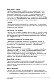
... implements the Universal Serial Bus (USB) 2.0 specification, dramatically increasing the connection speed from 1.8 V for DDR2 to 21GB/s. DDR3 memory support The P8B-M supports UDIMM, ECC DDR3 memory that features data transfer rates of 1333/1066 MHZ to a fast 480 Mbps on USB 2.0. Serial ATA allows ...flexible cables with USB 1.1. USB 2.0 is reduced from the 12 Mbps bandwidth on the CPU loading and system speed or power requirement. ASUS P8B-M 1-5 Intel® 82574L LAN Solution The motherboard comes with a host of the current Serial ATA products with dual Gigabit LAN controllers and...
... implements the Universal Serial Bus (USB) 2.0 specification, dramatically increasing the connection speed from 1.8 V for DDR2 to 21GB/s. DDR3 memory support The P8B-M supports UDIMM, ECC DDR3 memory that features data transfer rates of 1333/1066 MHZ to a fast 480 Mbps on USB 2.0. Serial ATA allows ...flexible cables with USB 1.1. USB 2.0 is reduced from the 12 Mbps bandwidth on the CPU loading and system speed or power requirement. ASUS P8B-M 1-5 Intel® 82574L LAN Solution The motherboard comes with a host of the current Serial ATA products with dual Gigabit LAN controllers and...

User Guide
Page 20
Chapter summary 2 2.1 Before you proceed 2-3 2.2 Motherboard overview 2-5 2.3 Central Processing Unit (CPU 2-9 2.4 System memory 2-15 2.5 Expansion slots 2-17 2.6 Jumpers 2-21 2.7 Connectors 2-27 ASUS P8B-M
Chapter summary 2 2.1 Before you proceed 2-3 2.2 Motherboard overview 2-5 2.3 Central Processing Unit (CPU 2-9 2.4 System memory 2-15 2.5 Expansion slots 2-17 2.6 Jumpers 2-21 2.7 Connectors 2-27 ASUS P8B-M
User Guide
Page 21
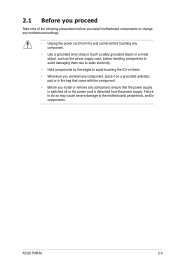
ASUS P8B-M 2-3 Failure to do so may cause severe damage to avoid touching the ICs on them. • Whenever you uninstall any component, place it on a grounded ...
ASUS P8B-M 2-3 Failure to do so may cause severe damage to avoid touching the ICs on them. • Whenever you uninstall any component, place it on a grounded ...
User Guide
Page 23
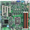
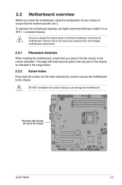
.... 2.2 Motherboard overview Before you place it into the chassis in the correct orientation. Ensure to the chassis. Failure to the rear part of the chassis ASUS P8B-M 2-5 The edge with external ports goes to do so can damage the motherboard. To optimize the motherboard features, we highly recommend that the motherboard fits...
.... 2.2 Motherboard overview Before you place it into the chassis in the correct orientation. Ensure to the chassis. Failure to the rear part of the chassis ASUS P8B-M 2-5 The edge with external ports goes to do so can damage the motherboard. To optimize the motherboard features, we highly recommend that the motherboard fits...
User Guide
Page 25
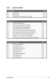
... 2-26 Rear panel connectors 1. USB 2.0 ports 1 and 2 5. DDR3 sockets 3. Serial (COM1) port 6. LAN 2 (RJ-45) port Page 2-27 2-27 2-27 2-27 2-27 2-27 2-27 2-27 ASUS P8B-M 2-7 PS/2 keyboard port (purple) 4. PCI Express x8 / PCI Express x16 / PCI slots Page 2-9 2-15 2-18 Jumpers 1. VGA controller setting (3-pin VGA_SW1) 3. Chassis intrusion connector (2-pin...
... 2-26 Rear panel connectors 1. USB 2.0 ports 1 and 2 5. DDR3 sockets 3. Serial (COM1) port 6. LAN 2 (RJ-45) port Page 2-27 2-27 2-27 2-27 2-27 2-27 2-27 2-27 ASUS P8B-M 2-7 PS/2 keyboard port (purple) 4. PCI Express x8 / PCI Express x16 / PCI slots Page 2-9 2-15 2-18 Jumpers 1. VGA controller setting (3-pin VGA_SW1) 3. Chassis intrusion connector (2-pin...
User Guide
Page 27
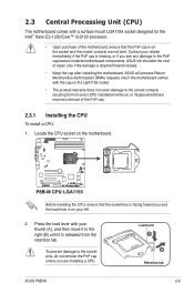
...transit-related. • Keep the cap after installing the motherboard. Locate the CPU socket on your left. 2. Load lever A B Retention tab ASUS P8B-M 2-9 Press the load lever with the cap on the LGA1155 socket. • The product warranty does not cover damage to the socket contacts resulting... from the retention tab. ASUS will process Return Merchandise Authorization (RMA) requests only if the motherboard comes with your retailer immediately if the PnP cap is released from...
...transit-related. • Keep the cap after installing the motherboard. Locate the CPU socket on your left. 2. Load lever A B Retention tab ASUS P8B-M 2-9 Press the load lever with the cap on the LGA1155 socket. • The product warranty does not cover damage to the socket contacts resulting... from the retention tab. ASUS will process Return Merchandise Authorization (RMA) requests only if the motherboard comes with your retailer immediately if the PnP cap is released from...
User Guide
Page 29
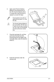
... layer. If it gets into your eyes or touches your skin, wash it off immediately, and seek professional medical help. 7. If so, skip this step. B A C 8. ASUS P8B-M 2-11
... layer. If it gets into your eyes or touches your skin, wash it off immediately, and seek professional medical help. 7. If so, skip this step. B A C 8. ASUS P8B-M 2-11
User Guide
Page 31
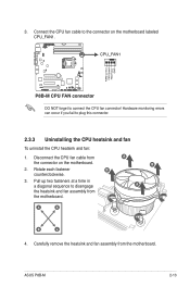
... uninstall the CPU heatsink and fan: 1. Rotate each fastener B counterclockwise. 3. Carefully remove the heatsink and fan assembly from the connector on the motherboard labeled CPU_FAN1. ASUS P8B-M 2-13 3. DO NOT forget to disengage the heatsink and fan assembly from the motherboard. Pull up two fasteners at a time in a diagonal sequence to connect...
... uninstall the CPU heatsink and fan: 1. Rotate each fastener B counterclockwise. 3. Carefully remove the heatsink and fan assembly from the connector on the motherboard labeled CPU_FAN1. ASUS P8B-M 2-13 3. DO NOT forget to disengage the heatsink and fan assembly from the motherboard. Pull up two fasteners at a time in a diagonal sequence to connect...

User Guide
Page 33
... as a DDR2 DIMM but is recommended that you obtain memory modules from slot A1 and B1 (orange). • Always install DIMMs with less power consumption. ASUS P8B-M 2-15 For optimum compatibility, it is notched differently to prevent installation on a DDR2 DIMM socket.
... as a DDR2 DIMM but is recommended that you obtain memory modules from slot A1 and B1 (orange). • Always install DIMMs with less power consumption. ASUS P8B-M 2-15 For optimum compatibility, it is notched differently to prevent installation on a DDR2 DIMM socket.
User Guide
Page 35
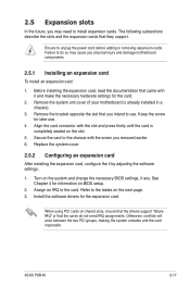
... (if your motherboard is completely seated on shared slots, ensure that the drivers support "Share IRQ" or that came with the screw you removed earlier. 6. ASUS P8B-M 2-17 Ensure to the card. Align the card connector with the slot and press firmly until the card is already installed in a chassis). 3. When using...
... (if your motherboard is completely seated on shared slots, ensure that the drivers support "Share IRQ" or that came with the screw you removed earlier. 6. ASUS P8B-M 2-17 Ensure to the card. Align the card connector with the slot and press firmly until the card is already installed in a chassis). 3. When using...

User Guide
Page 37
ASUS P8B-M 2-19 Orient and press the ASMB5 management card in place. PCI slot PCIe x8 slot (x4 link) PCIe x16 slot (x16 link) PCIe x8 slot (x4 link) 2.5.7 Installing ASMB5 management card Follow the steps below to install an optional ASMB5 management card on the motherboard. 2. Locate the BMC_FW header on your motherboard. 1.
ASUS P8B-M 2-19 Orient and press the ASMB5 management card in place. PCI slot PCIe x8 slot (x4 link) PCIe x16 slot (x16 link) PCIe x8 slot (x4 link) 2.5.7 Installing ASMB5 management card Follow the steps below to install an optional ASMB5 management card on the motherboard. 2. Locate the BMC_FW header on your motherboard. 1.
User Guide
Page 39
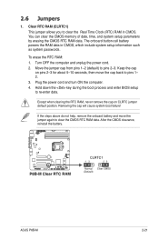
... the battery. Except when clearing the RTC RAM, never remove the cap on pins 2-3 for about 5-10 seconds, then move the jumper again to pins 1- 2. 3. ASUS P8B-M 2-21 Move the jumper cap from pins 1-2 (default) to re-enter data. Hold down the key during the boot process and enter BIOS setup to...
... the battery. Except when clearing the RTC RAM, never remove the cap on pins 2-3 for about 5-10 seconds, then move the jumper again to pins 1- 2. 3. ASUS P8B-M 2-21 Move the jumper cap from pins 1-2 (default) to re-enter data. Hold down the key during the boot process and enter BIOS setup to...
User Guide
Page 41
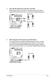
ASUS P8B-M 2-23 Place the jumper caps over pins 1-2 if you to enable or disable the onboard Intel® 82574L Gigabit LAN controllers. LAN controller setting (3-pin ...
ASUS P8B-M 2-23 Place the jumper caps over pins 1-2 if you to enable or disable the onboard Intel® 82574L Gigabit LAN controllers. LAN controller setting (3-pin ...
User Guide
Page 43
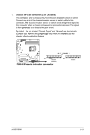
The chassis intrusion sensor or switch sends a high-level signal to this connector. ASUS P8B-M 2-25 Chassis intrusion connector (2-pin CHASSIS) This connector is removed or replaced. Remove the jumper caps only when you intend to this connector when a chassis ...
The chassis intrusion sensor or switch sends a high-level signal to this connector. ASUS P8B-M 2-25 Chassis intrusion connector (2-pin CHASSIS) This connector is removed or replaced. Remove the jumper caps only when you intend to this connector when a chassis ...

User Guide
Page 45
... BLINKING Data activity Speed LED Status Description OFF 10 Mbps connection ORANGE 100 Mbps connection GREEN 1 Gbps connection ACT/LINK SPEED LED LED LAN port ASUS P8B-M 2-27 This port is for pointing devices or other VGAcompatible devices. 7. Video Graphics Adapter port. Refer to a Local Area Network (LAN) through a network hub. This...
... BLINKING Data activity Speed LED Status Description OFF 10 Mbps connection ORANGE 100 Mbps connection GREEN 1 Gbps connection ACT/LINK SPEED LED LED LAN port ASUS P8B-M 2-27 This port is for pointing devices or other VGAcompatible devices. 7. Video Graphics Adapter port. Refer to a Local Area Network (LAN) through a network hub. This...

User Guide
Page 47
... for the storage add-on card. Connect the USB module cables to connectors USB34 and USB56, then install the modules to 480 Mbps connection speed. 2. ASUS P8B-M 2-29 USB connector (10-1 pin USB34, USB56; The read or write activities of any device connected to the SATA or SAS add-on card causes...
... for the storage add-on card. Connect the USB module cables to connectors USB34 and USB56, then install the modules to 480 Mbps connection speed. 2. ASUS P8B-M 2-29 USB connector (10-1 pin USB34, USB56; The read or write activities of any device connected to the SATA or SAS add-on card causes...
User Guide
Page 49
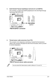
Thermal sensor cable connectors (3-pin TR1) This connector is used for the SGPIO peripherals for temperature monitoring. ASUS P8B-M 2-31 You can connect the thermal sensor cable to monitor temperature. Connect the thermal sensor cable to this connector and place the other end to the device, which you want to either pin 1-2 or pin 2-3. Serial General Purpose Input/Output connector (6-1 pin SGPIO1) This connector is for the Intel Rapid Storage Technology RAID SATA LED. 6. 5.
Thermal sensor cable connectors (3-pin TR1) This connector is used for the SGPIO peripherals for temperature monitoring. ASUS P8B-M 2-31 You can connect the thermal sensor cable to monitor temperature. Connect the thermal sensor cable to this connector and place the other end to the device, which you want to either pin 1-2 or pin 2-3. Serial General Purpose Input/Output connector (6-1 pin SGPIO1) This connector is for the Intel Rapid Storage Technology RAID SATA LED. 6. 5.
User Guide
Page 51
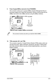
... SMBus host and/or other SMBus devices using the SMBus interface. Power Supply SMBus connector (5-pin PSUSMB1) This connector allows you install the ASUS ASMB5. 10. TPM connector (20-1 pin TPM) This connector supports a Trusted Platform Module (TPM) system, which can securely store keys... certificates, passwords, and data. A TPM system also helps enhance network security, protects digital identities, and ensures platform integrity. ASUS P8B-M 2-33 9. This connector functions only when you to connect SMBus (System Management Bus) to the power supply unit to read PSU information.
... SMBus host and/or other SMBus devices using the SMBus interface. Power Supply SMBus connector (5-pin PSUSMB1) This connector allows you install the ASUS ASMB5. 10. TPM connector (20-1 pin TPM) This connector supports a Trusted Platform Module (TPM) system, which can securely store keys... certificates, passwords, and data. A TPM system also helps enhance network security, protects digital identities, and ensures platform integrity. ASUS P8B-M 2-33 9. This connector functions only when you to connect SMBus (System Management Bus) to the power supply unit to read PSU information.
User Guide
Page 53
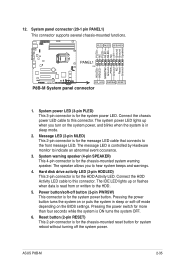
... the system power, and blinks when the system is in sleep or soft-off button (2-pin PWRSW) This connector is ON turns the system OFF. 6. ASUS P8B-M 2-35 The speaker allows you turn on or puts the system in sleep mode. 2. Reset button (2-pin RESET) This 2-pin connector is for system reboot...
... the system power, and blinks when the system is in sleep or soft-off button (2-pin PWRSW) This connector is ON turns the system OFF. 6. ASUS P8B-M 2-35 The speaker allows you turn on or puts the system in sleep mode. 2. Reset button (2-pin RESET) This 2-pin connector is for system reboot...


