
User Guide
Page 1
P7H55/USB3 Motherboard
P7H55/USB3 Motherboard
User Guide
Page 3
Contents Notices...vi Safety information vii About this guide viii P7H55/USB3 specifications summary ix Chapter 1: Product introduction 1.1 Before you proceed 1-1 1.2 Motherboard overview 1-2 1.2.1 Motherboard layout 1-2 1.2.2 Layout contents 1-2 1.3 Central Processing Unit (CPU 1-3 1.3.1 Installing the CPU 1-3 1.3.2 Installing the CPU heatsink and fan 1-6 1.3.3 Uninstalling the CPU heatsink and fan 1-7 1.4 System memory 1-8 1.4.1 Overview 1-8 1.4.2 ...
Contents Notices...vi Safety information vii About this guide viii P7H55/USB3 specifications summary ix Chapter 1: Product introduction 1.1 Before you proceed 1-1 1.2 Motherboard overview 1-2 1.2.1 Motherboard layout 1-2 1.2.2 Layout contents 1-2 1.3 Central Processing Unit (CPU 1-3 1.3.1 Installing the CPU 1-3 1.3.2 Installing the CPU heatsink and fan 1-6 1.3.3 Uninstalling the CPU heatsink and fan 1-7 1.4 System memory 1-8 1.4.1 Overview 1-8 1.4.2 ...
User Guide
Page 6
DO NOT throw the motherboard in municipal waste. This symbol of the crossed out wheeled bin indicates that the battery should not be placed in municipal waste. This symbol of ... harmful interference, and • This device must accept any interference received including interference that interference will not occur in our products at ASUS REACH website at http://green.asus.com/english/REACH.htm. Canadian Department of Communications. vi This equipment has been tested and found to enable proper reuse of electronic products...
DO NOT throw the motherboard in municipal waste. This symbol of the crossed out wheeled bin indicates that the battery should not be placed in municipal waste. This symbol of ... harmful interference, and • This device must accept any interference received including interference that interference will not occur in our products at ASUS REACH website at http://green.asus.com/english/REACH.htm. Canadian Department of Communications. vi This equipment has been tested and found to enable proper reuse of electronic products...
User Guide
Page 7
... the power cable from the electrical outlet before relocating the system. • When adding or removing devices to or from the motherboard, ensure that all power cables are unplugged. • Seek professional assistance before the signal cables are connected. Operation safety • Before installing... not be included in any damage, contact your regular household waste. If you are not sure about the voltage of the battery in your motherboard) and is set to fix it to a hazardous material collection point. • Never replace the battery with your dealer immediately. •...
... the power cable from the electrical outlet before relocating the system. • When adding or removing devices to or from the motherboard, ensure that all power cables are unplugged. • Seek professional assistance before the signal cables are connected. Operation safety • Before installing... not be included in any damage, contact your regular household waste. If you are not sure about the voltage of the battery in your motherboard) and is set to fix it to a hazardous material collection point. • Never replace the battery with your dealer immediately. •...
User Guide
Page 8
...++ viii Refer to complete a task. Conventions used throughout this manual. CAUTION: Information to prevent damage to the components when trying to the ASUS contact information. 2. Typography Bold text Italics ++ Indicates a menu or an item to emphasize a word or a phrase. Used to select.... dealer. DANGER/WARNING: Information to prevent injury to yourself when trying to help you need when installing and configuring the motherboard. These documents are also provided. How this guide is organized This guide contains the following sources for additional information and...
...++ viii Refer to complete a task. Conventions used throughout this manual. CAUTION: Information to prevent damage to the components when trying to the ASUS contact information. 2. Typography Bold text Italics ++ Indicates a menu or an item to emphasize a word or a phrase. Used to select.... dealer. DANGER/WARNING: Information to prevent injury to yourself when trying to help you need when installing and configuring the motherboard. These documents are also provided. How this guide is organized This guide contains the following sources for additional information and...
User Guide
Page 13
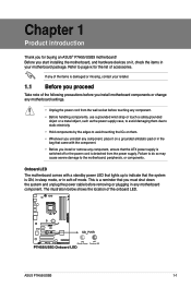
..., or components. Failure to do so may cause severe damage to page ix for buying an ASUS® P7H55/USB3 motherboard! ASUS P7H55/USB3 1-1 Before you install motherboard components or change any motherboard component. This is ON, in sleep mode, or in your retailer. 1.1 Before you proceed Take note of the following precautions before touching any component. • ...
..., or components. Failure to do so may cause severe damage to page ix for buying an ASUS® P7H55/USB3 motherboard! ASUS P7H55/USB3 1-1 Before you install motherboard components or change any motherboard component. This is ON, in sleep mode, or in your retailer. 1.1 Before you proceed Take note of the following precautions before touching any component. • ...
User Guide
Page 14
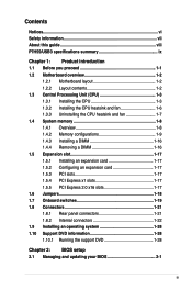
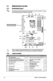
...1-24 1-19 13. switch 7. Digital audio connector (4-1 pin SPDIF_OUT) 1-23 1-20 12. Turbo Key II switch 6. Doing so can damage the motherboard. 1.2.2 Layout contents Connectors/Jumpers/Slots/LED 1. LGA1156 CPU Socket 4. The edge with external ports goes to the chassis. DO NOT overtighten the screws!...27 1-3 10. Intel® H55 Serial ATA connectors (7-pin SATA 1-6) Page Connectors/Jumpers/Slots/LED Page 1-22 8. DDR3 DIMM slots 5. 1.2 1.2.1 Motherboard overview Motherboard layout Ensure that you install the motherboard into the holes indicated by circles to secure the...
...1-24 1-19 13. switch 7. Digital audio connector (4-1 pin SPDIF_OUT) 1-23 1-20 12. Turbo Key II switch 6. Doing so can damage the motherboard. 1.2.2 Layout contents Connectors/Jumpers/Slots/LED 1. LGA1156 CPU Socket 4. The edge with external ports goes to the chassis. DO NOT overtighten the screws!...27 1-3 10. Intel® H55 Serial ATA connectors (7-pin SATA 1-6) Page Connectors/Jumpers/Slots/LED Page 1-22 8. DDR3 DIMM slots 5. 1.2 1.2.1 Motherboard overview Motherboard layout Ensure that you install the motherboard into the holes indicated by circles to secure the...
User Guide
Page 15
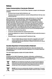
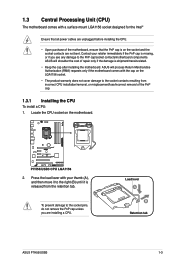
...with the cap on the LGA1156 socket. • The product warranty does not cover damage to the PnP cap/socket contacts/motherboard components. Load lever A B Retention tab ASUS P7H55/USB3 1-3 Press the load lever with your retailer immediately if the PnP cap is missing, or if you are not bent. ...are unplugged before installing the CPU. • Upon purchase of the motherboard, ensure that the PnP cap is on the motherboard. 2. Locate the CPU socket on the socket and the socket contacts are installing a CPU. ASUS will shoulder the cost of repair only if the damage is shipment/transit...
...with the cap on the LGA1156 socket. • The product warranty does not cover damage to the PnP cap/socket contacts/motherboard components. Load lever A B Retention tab ASUS P7H55/USB3 1-3 Press the load lever with your retailer immediately if the PnP cap is missing, or if you are not bent. ...are unplugged before installing the CPU. • Upon purchase of the motherboard, ensure that the PnP cap is on the motherboard. 2. Locate the CPU socket on the socket and the socket contacts are installing a CPU. ASUS will shoulder the cost of repair only if the damage is shipment/transit...

User Guide
Page 18
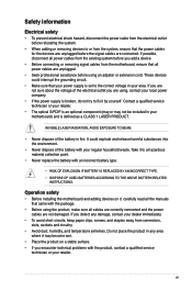
.... 1-6 Chapter 1: Product introduction Place the heatsink on top of the installed CPU, making sure that the four fasteners match the holes on the motherboard. 2. If you buy a boxed Intel® processor, the package includes the CPU fan and heatsink assembly. Push down two fasteners at a ...time in B a diagonal sequence to secure the heatsink and fan assembly in place. Ensure that you have installed the motherboard to the chassis before you install the CPU fan and heatsink assembly. A B A A B 1 B A 1 Orient the heatsink and fan assembly such...
.... 1-6 Chapter 1: Product introduction Place the heatsink on top of the installed CPU, making sure that the four fasteners match the holes on the motherboard. 2. If you buy a boxed Intel® processor, the package includes the CPU fan and heatsink assembly. Push down two fasteners at a ...time in B a diagonal sequence to secure the heatsink and fan assembly in place. Ensure that you have installed the motherboard to the chassis before you install the CPU fan and heatsink assembly. A B A A B 1 B A 1 Orient the heatsink and fan assembly such...
User Guide
Page 19
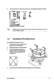
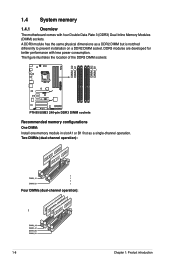
... connect the CPU fan connector! Rotate each fastener counterclockwise. 3. A B A A B B A 4. Disconnect the CPU fan cable from the motherboard. ASUS P7H55/USB3 1-7 DO NOT forget to plug this connector. 1.3.3 Uninstalling the CPU heatsink and fan To uninstall the CPU heatsink and fan: 1. Carefully remove... the heatsink and fan assembly from the connector on the motherboard labeled CPU_FAN. Pull up two fasteners at a time in a B diagonal sequence to the connector on the motherboard. 2. Connect the CPU fan cable to disengage the heatsink and ...
... connect the CPU fan connector! Rotate each fastener counterclockwise. 3. A B A A B B A 4. Disconnect the CPU fan cable from the motherboard. ASUS P7H55/USB3 1-7 DO NOT forget to plug this connector. 1.3.3 Uninstalling the CPU heatsink and fan To uninstall the CPU heatsink and fan: 1. Carefully remove... the heatsink and fan assembly from the connector on the motherboard labeled CPU_FAN. Pull up two fasteners at a time in a B diagonal sequence to the connector on the motherboard. 2. Connect the CPU fan cable to disengage the heatsink and ...
User Guide
Page 20
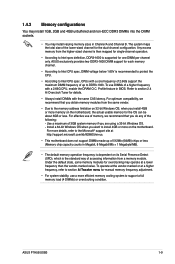
... module in slot A1 or B1 first as a DDR2 DIMM but is notched differently to prevent installation on a DDR2 DIMM socket. 1.4 System memory 1.4.1 Overview The motherboard comes with less power consumption. DDR3 modules are developed for better performance with four Double Data Rate 3 (DDR3) Dual Inline Memory Modules (DIMM) sockets. A DDR3...
... module in slot A1 or B1 first as a DDR2 DIMM but is notched differently to prevent installation on a DDR2 DIMM socket. 1.4 System memory 1.4.1 Overview The motherboard comes with less power consumption. DDR3 modules are developed for better performance with four Double Data Rate 3 (DDR3) Dual Inline Memory Modules (DIMM) sockets. A DDR3...
User Guide
Page 21
...on the motherboard, the actual usable memory for the OS can be about 3GB or less. Use a maximum of a higher frequency with the same CAS latency. Under the default state, some memory modules for details. • Always install DIMMs with a 2.66G CPU, enable the DRAM O.C. ASUS P7H55/USB3 1-9 Refer...Profile feature in Channel A and Channel B. Any excess memory from the same vendor. • Due to the memory address limitation on the motherboard. 1.4.2 Memory configurations You may install 1GB, 2GB and 4GB unbuffered and non‑ECC DDR3 DIMMs into the DIMM sockets. • You ...
...on the motherboard, the actual usable memory for the OS can be about 3GB or less. Use a maximum of a higher frequency with the same CAS latency. Under the default state, some memory modules for details. • Always install DIMMs with a 2.66G CPU, enable the DRAM O.C. ASUS P7H55/USB3 1-9 Refer...Profile feature in Channel A and Channel B. Any excess memory from the same vendor. • Due to the memory address limitation on the motherboard. 1.4.2 Memory configurations You may install 1GB, 2GB and 4GB unbuffered and non‑ECC DDR3 DIMMs into the DIMM sockets. • You ...
User Guide
Page 22
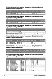
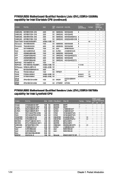
...Chapter 1: Product introduction Timing DS - - 9-9-9-24 Voltage 1.65 DIMM socket support (Optional) A* B* C* • P7H55/USB3 Motherboard Qualified Vendors Lists (QVL) DDR3-2133MHz capability for Intel Lynnfield CPU Vendor Part No. SS - - Patriot PVS32G1866LLK(XMP... - - - - - - - - - - - - - - Voltage 1.65 DIMM socket support (Optional) A* B* C* • • P7H55/USB3 Motherboard Qualified Vendors Lists (QVL) DDR3-1600MHz capability for Intel Lynnfield CPU Vendor Part No. Timing DS - - 9-9-9-28 Voltage 1.65 DIMM socket support (Optional)...
...Chapter 1: Product introduction Timing DS - - 9-9-9-24 Voltage 1.65 DIMM socket support (Optional) A* B* C* • P7H55/USB3 Motherboard Qualified Vendors Lists (QVL) DDR3-2133MHz capability for Intel Lynnfield CPU Vendor Part No. SS - - Patriot PVS32G1866LLK(XMP... - - - - - - - - - - - - - - Voltage 1.65 DIMM socket support (Optional) A* B* C* • • P7H55/USB3 Motherboard Qualified Vendors Lists (QVL) DDR3-1600MHz capability for Intel Lynnfield CPU Vendor Part No. Timing DS - - 9-9-9-28 Voltage 1.65 DIMM socket support (Optional)...
User Guide
Page 26
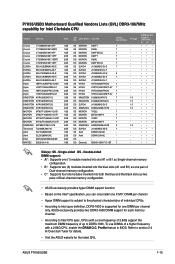
... PVS34G1333ELK Patriot PVT36G1333ELK Silicon Power Silicon Power SP001GBLTU1333S01 SP001GBLTU133S02 Size SS/ DS Chip Brand Chip NO. P7H55/USB3 Motherboard Qualified Vendors Lists (QVL) DDR3-1333MHz capability for Intel Lynnfield CPU Vendor Crucial Crucial ELPIDA ELPIDA ... •• •• ••• •• ••• ••• •• P7H55/USB3 Motherboard Qualified Vendors Lists (QVL) DDR3-1067MHz capability for Intel Clarkdale CPU (continued) Vendor Part No. Asint DDRIII1208-AE - - - -...
... PVS34G1333ELK Patriot PVT36G1333ELK Silicon Power Silicon Power SP001GBLTU1333S01 SP001GBLTU133S02 Size SS/ DS Chip Brand Chip NO. P7H55/USB3 Motherboard Qualified Vendors Lists (QVL) DDR3-1333MHz capability for Intel Lynnfield CPU Vendor Crucial Crucial ELPIDA ELPIDA ... •• •• ••• •• ••• ••• •• P7H55/USB3 Motherboard Qualified Vendors Lists (QVL) DDR3-1067MHz capability for Intel Clarkdale CPU (continued) Vendor Part No. Asint DDRIII1208-AE - - - -...
User Guide
Page 27
...-EAE 1GB Asint SLZ3128M8-EAE 2GB Elixir M2Y2G64CB8HA9N-BE 2GB WINTEC 3DU3191A-10 1GB SS/ DS Chip Brand Chip NO. ASUS exclusively provides two DDR3-1600 DIMM support for the latest QVL. P7H55/USB3 Motherboard Qualified Vendors Lists (QVL) DDR3-1067MHz capability for one X.M.P. To use DIMMs of individual CPUs. • According to the...
...-EAE 1GB Asint SLZ3128M8-EAE 2GB Elixir M2Y2G64CB8HA9N-BE 2GB WINTEC 3DU3191A-10 1GB SS/ DS Chip Brand Chip NO. ASUS exclusively provides two DDR3-1600 DIMM support for the latest QVL. P7H55/USB3 Motherboard Qualified Vendors Lists (QVL) DDR3-1067MHz capability for one X.M.P. To use DIMMs of individual CPUs. • According to the...
User Guide
Page 28
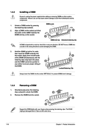
1.4.3 Installing a DIMM Ensure to both the motherboard and the components. 1. DIMM notch 2. Apply force to both of the DIMM. 3 Locked Retaining Clip Always insert the DIMM into the socket VERTICALLY to ensure ...
1.4.3 Installing a DIMM Ensure to both the motherboard and the components. 1. DIMM notch 2. Apply force to both of the DIMM. 3 Locked Retaining Clip Always insert the DIMM into the socket VERTICALLY to ensure ...
User Guide
Page 29
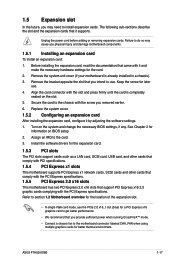
...card, read the documentation that it by adjusting the software settings. 1. Remove the system unit cover (if your motherboard is completely seated on the slot. 5. ASUS P7H55/USB3 1-17 The following sub‑sections describe the slot and the expansion cards that came with the PCI Express ...specifications. 1.5.5 PCI Express 2.0 x16 slots This motherboard has two PCI Express 2.0 x16 slots that you removed earlier. 6. ...
...card, read the documentation that it by adjusting the software settings. 1. Remove the system unit cover (if your motherboard is completely seated on the slot. 5. ASUS P7H55/USB3 1-17 The following sub‑sections describe the slot and the expansion cards that came with the PCI Express ...specifications. 1.5.5 PCI Express 2.0 x16 slots This motherboard has two PCI Express 2.0 x16 slots that you removed earlier. 6. ...
User Guide
Page 31
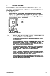
...DIMMs still fail to enhance system performance. 1. If the test fails, the system reboots and test the next set of failsafe settings. ASUS P7H55/USB3 1-19 1.7 Onboard switches Onboard switch allows you turn off the system and reinstall the DIMM before using the MemOK! This is not...memory tuning. • During the tuning process, the system loads and tests failsafe memory settings. MemOK! Replace the DIMMs with the motherboard may cause system boot failure, and the DRAM_LED near the MemOK! switch lights continuously. switch under Windows™ OS environment will ...
...DIMMs still fail to enhance system performance. 1. If the test fails, the system reboots and test the next set of failsafe settings. ASUS P7H55/USB3 1-19 1.7 Onboard switches Onboard switch allows you turn off the system and reinstall the DIMM before using the MemOK! This is not...memory tuning. • During the tuning process, the system loads and tests failsafe memory settings. MemOK! Replace the DIMMs with the motherboard may cause system boot failure, and the DRAM_LED near the MemOK! switch lights continuously. switch under Windows™ OS environment will ...
User Guide
Page 35
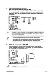
Connect the S/PDIF Out module cable to this connector, then install the module to the motherboard connector labeled CHA_FAN for an additional Sony/Philips Digital Interface (S/PDIF) port(s). CPU, chassis, and power fan connectors (4-pin CPU_FAN, 3-pin CHA_FAN...slot opening at +12V. 2. Insufficient air flow inside the system may damage the motherboard components. Digital audio connector (4-1 pin SPDIF_OUT) This connector is purchased separately. Connect the fan cables to the fan connectors. ASUS P7H55/USB3 1-23 Do not forget to connect the fan cables to the fan connectors on ...
Connect the S/PDIF Out module cable to this connector, then install the module to the motherboard connector labeled CHA_FAN for an additional Sony/Philips Digital Interface (S/PDIF) port(s). CPU, chassis, and power fan connectors (4-pin CPU_FAN, 3-pin CHA_FAN...slot opening at +12V. 2. Insufficient air flow inside the system may damage the motherboard components. Digital audio connector (4-1 pin SPDIF_OUT) This connector is purchased separately. Connect the fan cables to the fan connectors. ASUS P7H55/USB3 1-23 Do not forget to connect the fan cables to the fan connectors on ...

User Guide
Page 36
Front panel audio connector (10-1 pin AAFP) This connector is set to a slot opening at the back of the motherboard's high-definition audio capability. • If you want to connect a high-definition front panel audio module to this connector. • We recommend that supports either ...
Front panel audio connector (10-1 pin AAFP) This connector is set to a slot opening at the back of the motherboard's high-definition audio capability. • If you want to connect a high-definition front panel audio module to this connector. • We recommend that supports either ...


