User Guide
Page 3
Contents Notices...vi Safety information vii About this guide viii P7H55/USB3 specifications summary ix Chapter 1: Product introduction 1.1 Before you proceed 1-1 1.2 Motherboard overview 1-2 1.2.1 Motherboard layout 1-2 1.2.2 Layout contents 1-2 1.3 Central ...17 1.5.4 PCI Express x1 slots 1-17 1.5.5 PCI Express 2.0 x16 slots 1-17 1.6 Jumpers 1-18 1.7 Onboard switches 1-19 1.8 Connectors 1-21 1.8.1 Rear panel connectors 1-21 1.8.2 Internal connectors 1-22 1.9 Installing an operating system 1-28 1.10 Support DVD information 1-28 1.10.1 Running the support DVD 1-28 Chapter 2: BIOS...
Contents Notices...vi Safety information vii About this guide viii P7H55/USB3 specifications summary ix Chapter 1: Product introduction 1.1 Before you proceed 1-1 1.2 Motherboard overview 1-2 1.2.1 Motherboard layout 1-2 1.2.2 Layout contents 1-2 1.3 Central ...17 1.5.4 PCI Express x1 slots 1-17 1.5.5 PCI Express 2.0 x16 slots 1-17 1.6 Jumpers 1-18 1.7 Onboard switches 1-19 1.8 Connectors 1-21 1.8.1 Rear panel connectors 1-21 1.8.2 Internal connectors 1-22 1.9 Installing an operating system 1-28 1.10 Support DVD information 1-28 1.10.1 Running the support DVD 1-28 Chapter 2: BIOS...
User Guide
Page 7
... safety • Before installing the motherboard and adding devices on a stable surface. • If you add a device. • Before connecting or removing signal cables from connectors, slots, sockets and circuitry. • Avoid dust, humidity, and temperature extremes. Do not place the product in fire. INVISIBLE LASER RADIATION, AVOID EXPOSURE TO BEAM...
... safety • Before installing the motherboard and adding devices on a stable surface. • If you add a device. • Before connecting or removing signal cables from connectors, slots, sockets and circuitry. • Avoid dust, humidity, and temperature extremes. Do not place the product in fire. INVISIBLE LASER RADIATION, AVOID EXPOSURE TO BEAM...
User Guide
Page 11
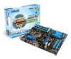
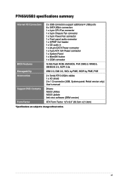
xi P7H55/USB3 specifications summary Internal I /O shield 2 in 1 x 24-pin EATX Power connector 1 x 4-pin ATX 12V Power connector 1 x System Panel 1 x MemOK! button 1 x COM connector 16 Mb Flash ROM, AMI BIOS, PnP, DMI2.0, WfM2.0, SM BIOS 2.5, ACPI 2.0a WfM 2.0, DMI 2.0, WOL by PME, WOR by PME, PXE 2 x Serial ATA 3.0Gb/s cables 1 x I /O Connectors BIOS Features Manageability Accessories Support DVD...
xi P7H55/USB3 specifications summary Internal I /O shield 2 in 1 x 24-pin EATX Power connector 1 x 4-pin ATX 12V Power connector 1 x System Panel 1 x MemOK! button 1 x COM connector 16 Mb Flash ROM, AMI BIOS, PnP, DMI2.0, WfM2.0, SM BIOS 2.5, ACPI 2.0a WfM 2.0, DMI 2.0, WOL by PME, WOR by PME, PXE 2 x Serial ATA 3.0Gb/s cables 1 x I /O Connectors BIOS Features Manageability Accessories Support DVD...
User Guide
Page 14
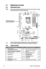
...orientation. Doing so can damage the motherboard. 1.2.2 Layout contents Connectors/Jumpers/Slots/LED 1. ATX power connectors (24-pin EATXPWR, 4-pin EATX12V) 2. Clear RTC RAM (3-pin CLRTC) 1-18 1-8 11. Serial port connector (10-1 pin COM1) 1-24 1-2 Chapter 1: Product introduction... DO NOT overtighten the screws! Turbo Key II switch 6. switch 7. System panel connector (20-8 pin PANEL) 1-26 1-23 9. Front panel audio connector (10-1 pin AAFP) 1-24 1-19 13. LGA1156 CPU Socket 4. MemOK! Onboard LED 1-1 1-25 14. DDR3...
...orientation. Doing so can damage the motherboard. 1.2.2 Layout contents Connectors/Jumpers/Slots/LED 1. ATX power connectors (24-pin EATXPWR, 4-pin EATX12V) 2. Clear RTC RAM (3-pin CLRTC) 1-18 1-8 11. Serial port connector (10-1 pin COM1) 1-24 1-2 Chapter 1: Product introduction... DO NOT overtighten the screws! Turbo Key II switch 6. switch 7. System panel connector (20-8 pin PANEL) 1-26 1-23 9. Front panel audio connector (10-1 pin AAFP) 1-24 1-19 13. LGA1156 CPU Socket 4. MemOK! Onboard LED 1-1 1-25 14. DDR3...
User Guide
Page 16
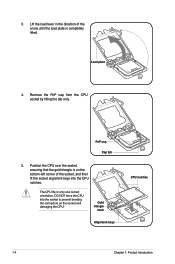
... Remove the PnP cap from the CPU socket by lifting the tab only. DO NOT force the CPU into the socket to prevent bending the connectors on the bottom‑left corner of the arrow until the load plate is on the socket and damaging the CPU! Load plate 4. PnP cap...
... Remove the PnP cap from the CPU socket by lifting the tab only. DO NOT force the CPU into the socket to prevent bending the connectors on the bottom‑left corner of the arrow until the load plate is on the socket and damaging the CPU! Load plate 4. PnP cap...

User Guide
Page 18
... fan and heatsink assembly. Place the heatsink on top of the installed CPU, making sure that you have installed the motherboard to the CPU fan connector. 1-6 Chapter 1: Product introduction A B A A B 1 B A 1 Orient the heatsink and fan assembly such that the Thermal Interface Material is properly applied to secure the heatsink and fan assembly...
... fan and heatsink assembly. Place the heatsink on top of the installed CPU, making sure that you have installed the motherboard to the CPU fan connector. 1-6 Chapter 1: Product introduction A B A A B 1 B A 1 Orient the heatsink and fan assembly such that the Thermal Interface Material is properly applied to secure the heatsink and fan assembly...
User Guide
Page 19
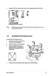
... up two fasteners at a time in a B diagonal sequence to the connector on the motherboard. 2. Disconnect the CPU fan cable from the motherboard. Carefully remove the heatsink and fan assembly from the connector on the motherboard labeled CPU_FAN. Rotate each fastener counterclockwise. 3. ASUS P7H55/USB3 1-7 Connect the CPU fan cable to disengage the heatsink and fan...
... up two fasteners at a time in a B diagonal sequence to the connector on the motherboard. 2. Disconnect the CPU fan cable from the motherboard. Carefully remove the heatsink and fan assembly from the connector on the motherboard labeled CPU_FAN. Rotate each fastener counterclockwise. 3. ASUS P7H55/USB3 1-7 Connect the CPU fan cable to disengage the heatsink and fan...
User Guide
Page 29
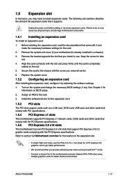
... Expansion slot In the future, you provide sufficient power when running CrossFireX™ mode. • Connect a chassis fan to the motherboard connector labeled CHA_FAN when using multiple graphics cards for better thermal environment. Keep the screw for later use . See Chapter 2 for the expansion ...cards and other cards that comply with the slot and press firmly until the card is already installed in a chassis). 3. ASUS P7H55/USB3 1-17 Before installing the expansion card, read the documentation that you may cause you physical injury and damage motherboard components. 1.5.1...
... Expansion slot In the future, you provide sufficient power when running CrossFireX™ mode. • Connect a chassis fan to the motherboard connector labeled CHA_FAN when using multiple graphics cards for better thermal environment. Keep the screw for later use . See Chapter 2 for the expansion ...cards and other cards that comply with the slot and press firmly until the card is already installed in a chassis). 3. ASUS P7H55/USB3 1-17 Before installing the expansion card, read the documentation that you may cause you physical injury and damage motherboard components. 1.5.1...
User Guide
Page 33
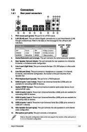
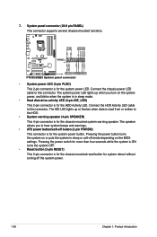
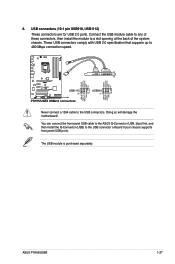
1.8 Connectors 1.8.1 Rear panel connectors 1. PS/2 mouse port (green). LAN (RJ-45) port. ACT/LINK LED Status Description SPEED LED Status Description ACT/LINK SPEED LED LED OFF No link ... port LED indicators. These two 4-pin Universal Serial Bus (USB) ports connect to a Local Area Network (LAN) through a network hub. Side Speaker Out port (gray). ASUS P7H55/USB3 1-21
1.8 Connectors 1.8.1 Rear panel connectors 1. PS/2 mouse port (green). LAN (RJ-45) port. ACT/LINK LED Status Description SPEED LED Status Description ACT/LINK SPEED LED LED OFF No link ... port LED indicators. These two 4-pin Universal Serial Bus (USB) ports connect to a Local Area Network (LAN) through a network hub. Side Speaker Out port (gray). ASUS P7H55/USB3 1-21
User Guide
Page 34
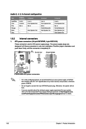
... power supply unit (PSU) that you are uncertain about the minimum power supply requirement for your system, refer to fit these connectors in only one orientation. com/PowerSupplyCalculator/PSCalculator.aspx?SLanguage=en-us for ATX power supply plugs. Audio 2, 4, 6, 8-channel ...Mic In Center/Subwoofer Rear Speaker Out Side Speaker Out 1.8.2 Internal connectors 1. ATX power connectors (24-pin EATXPWR, 4-pin EATX12V) These connectors are designed to the Recommended Power Supply Wattage Calculator at http://support.asus. The power supply plugs are for details. 1-22 Chapter 1:...
... power supply unit (PSU) that you are uncertain about the minimum power supply requirement for your system, refer to fit these connectors in only one orientation. com/PowerSupplyCalculator/PSCalculator.aspx?SLanguage=en-us for ATX power supply plugs. Audio 2, 4, 6, 8-channel ...Mic In Center/Subwoofer Rear Speaker Out Side Speaker Out 1.8.2 Internal connectors 1. ATX power connectors (24-pin EATXPWR, 4-pin EATX12V) These connectors are designed to the Recommended Power Supply Wattage Calculator at http://support.asus. The power supply plugs are for details. 1-22 Chapter 1:...
User Guide
Page 35
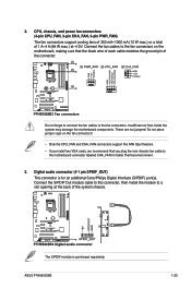
... two VGA cards, we recommend that the black wire of each cable matches the ground pin of the connector. Connect the S/PDIF Out module cable to this connector, then install the module to the fan connectors. ASUS P7H55/USB3 1-23 The S/PDIF module is for better thermal environment. 3. Do not forget to connect the fan cables...
... two VGA cards, we recommend that the black wire of each cable matches the ground pin of the connector. Connect the S/PDIF Out module cable to this connector, then install the module to the fan connectors. ASUS P7H55/USB3 1-23 The S/PDIF module is for better thermal environment. 3. Do not forget to connect the fan cables...

User Guide
Page 36
...for a chassis-mounted front panel audio I /O module cable to [AC97]. If you want to connect an AC'97 front panel audio module to this connector, then install the module to a slot opening at the back of the front panel audio I /O module that you connect a high-definition front panel... audio module to this connector to avail of the motherboard's high-definition audio capability. • If you want to connect a high-definition front panel audio module to [HD Audio]. ...
...for a chassis-mounted front panel audio I /O module cable to [AC97]. If you want to connect an AC'97 front panel audio module to this connector, then install the module to a slot opening at the back of the front panel audio I /O module that you connect a high-definition front panel... audio module to this connector to avail of the motherboard's high-definition audio capability. • If you want to connect a high-definition front panel audio module to [HD Audio]. ...
User Guide
Page 37
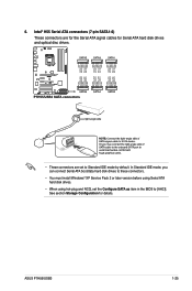
6. In Standard IDE mode, you can connect Serial ATA boot/data hard disk drives to these connectors. • You must install Windows® XP Service Pack 2 or later version before using Serial ATA hard disk drives. • When using hot-plug ... See section Storage Configuration for Serial ATA hard disk drives and optical disc drives. • These connectors are for the Serial ATA signal cables for details. ASUS P7H55/USB3 1-25 Intel® H55 Serial ATA connectors (7-pin SATA1-6) These connectors are set the Configure SATA as item in the BIOS to Standard IDE mode by default.
6. In Standard IDE mode, you can connect Serial ATA boot/data hard disk drives to these connectors. • You must install Windows® XP Service Pack 2 or later version before using Serial ATA hard disk drives. • When using hot-plug ... See section Storage Configuration for Serial ATA hard disk drives and optical disc drives. • These connectors are for the Serial ATA signal cables for details. ASUS P7H55/USB3 1-25 Intel® H55 Serial ATA connectors (7-pin SATA1-6) These connectors are set the Configure SATA as item in the BIOS to Standard IDE mode by default.
User Guide
Page 38
...or flashes when data is for the HDD Activity LED. System panel connector (20-8 pin PANEL) This connector supports several chassis-mounted functions. • System power LED (2-pin PLED) This 2-pin connector is read from or written to this connector. Connect the HDD Activity LED cable to the HDD. •...Connect the chassis power LED cable to hear system beeps and warnings. • ATX power button/soft-off button (2-pin PWRSW) This connector is for system reboot without turning off mode depending on the system power, and blinks when the system is for the chassis-mounted system ...
...or flashes when data is for the HDD Activity LED. System panel connector (20-8 pin PANEL) This connector supports several chassis-mounted functions. • System power LED (2-pin PLED) This 2-pin connector is read from or written to this connector. Connect the HDD Activity LED cable to the HDD. •...Connect the chassis power LED cable to hear system beeps and warnings. • ATX power button/soft-off button (2-pin PWRSW) This connector is for system reboot without turning off mode depending on the system power, and blinks when the system is for the chassis-mounted system ...
User Guide
Page 39
... for USB 2.0 ports. Doing so will damage the motherboard! ASUS P7H55/USB3 1-27 8. The USB module is purchased separately. These USB connectors comply with USB 2.0 specification that supports up to a slot opening at the back of these connectors, then install the module to 480 Mbps connection speed. Connect ...the USB module cable to any of the system chassis. Never connect a 1394 cable to the USB connector onboard if your chassis supports front panel USB ports. You can connect the front panel USB cable to the ASUS Q-Connector (USB, blue) first, and then install the...
... for USB 2.0 ports. Doing so will damage the motherboard! ASUS P7H55/USB3 1-27 8. The USB module is purchased separately. These USB connectors comply with USB 2.0 specification that supports up to a slot opening at the back of these connectors, then install the module to 480 Mbps connection speed. Connect ...the USB module cable to any of the system chassis. Never connect a 1394 cable to the USB connector onboard if your chassis supports front panel USB ports. You can connect the front panel USB cable to the ASUS Q-Connector (USB, blue) first, and then install the...
User Guide
Page 46
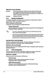
...: [Disabled] [Enabled] 2-6 Chapter 2: BIOS information It appears only when you to set the item Configure SATA as fewer transactions are needed for the Serial ATA connectors supported by allowing the drive to internally optimize the order of SATA devices. Configuration options: [0] [5] [10] [15] [20] [25] [30] [35] 2.3.3 AHCI Configuration This menu...
...: [Disabled] [Enabled] 2-6 Chapter 2: BIOS information It appears only when you to set the item Configure SATA as fewer transactions are needed for the Serial ATA connectors supported by allowing the drive to internally optimize the order of SATA devices. Configuration options: [0] [5] [10] [15] [20] [25] [30] [35] 2.3.3 AHCI Configuration This menu...
User Guide
Page 57
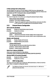
...Disabled] Disables the controller. Front Panel Type [HD Audio] [AC97] Set the front panel audio connector (AAFP) mode to legacy AC'97 [HD Audio] Set the front panel audio connector (AAFP) mode to display the configuration options. Configuration options: [Disabled] [3F8/IRQ4] [2F8/... change the advanced chipset settings. Realtek LAN1 [Enabled] [Enabled] Enables Realtek LAN Controller. [Disabled] Disables Realtek LAN Controller. ASUS P7H55/USB3 2-17 Select an item then press to high-definition audio. We recommend that was previously overwritten by your CPU. Serial Port1 ...
...Disabled] Disables the controller. Front Panel Type [HD Audio] [AC97] Set the front panel audio connector (AAFP) mode to legacy AC'97 [HD Audio] Set the front panel audio connector (AAFP) mode to display the configuration options. Configuration options: [Disabled] [3F8/IRQ4] [2F8/... change the advanced chipset settings. Realtek LAN1 [Enabled] [Enabled] Enables Realtek LAN Controller. [Disabled] Disables Realtek LAN Controller. ASUS P7H55/USB3 2-17 Select an item then press to high-definition audio. We recommend that was previously overwritten by your CPU. Serial Port1 ...


