
User Manual
Page 1
P7H55-M SI Motherboard
P7H55-M SI Motherboard

User Manual
Page 3
Contents Notices...v Safety information vi About this guide vi P7H55-M SI specifications summary viii Chapter 1: Product introduction 1.1 Before you proceed 1-1 1.2 Motherboard overview 1-2 1.2.1 Motherboard layout 1-2 1.2.2 Layout contents 1-2 1.3 Central Processing Unit (CPU 1-3 1.4 System memory 1-3 1.4.1 Overview 1-3 1.4.2 Memory configurations 1-4 1.5 Expansion... DVD information 1-18 Chapter 2: BIOS information 2.1 Managing and updating your BIOS 2-1 2.1.1 ASUS Update utility 2-1 2.1.2 ASUS EZ Flash 2 utility 2-2 2.1.3 ASUS BIOS Updater 2-3 2.1.4 ASUS CrashFree BIOS 2-6 iii
Contents Notices...v Safety information vi About this guide vi P7H55-M SI specifications summary viii Chapter 1: Product introduction 1.1 Before you proceed 1-1 1.2 Motherboard overview 1-2 1.2.1 Motherboard layout 1-2 1.2.2 Layout contents 1-2 1.3 Central Processing Unit (CPU 1-3 1.4 System memory 1-3 1.4.1 Overview 1-3 1.4.2 Memory configurations 1-4 1.5 Expansion... DVD information 1-18 Chapter 2: BIOS information 2.1 Managing and updating your BIOS 2-1 2.1.1 ASUS Update utility 2-1 2.1.2 ASUS EZ Flash 2 utility 2-2 2.1.3 ASUS BIOS Updater 2-3 2.1.4 ASUS CrashFree BIOS 2-6 iii
User Manual
Page 11
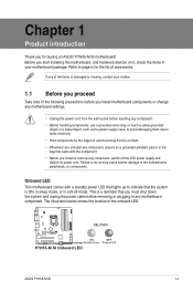
.... Failure to do so may cause severe damage to page ix for buying an ASUS® P7H55-M SI motherboard! Before you start installing the motherboard, and hardware devices on it on a grounded antistatic pad or in the bag that came with a standby power LED ... place it , check the items in your retailer. 1.1 Before you proceed Take note of accessories. SB_PWR P7H55-M SI ON OFF Standby Power Powered Off P7H55-M SI Onboard LED ASUS P7H55-M SI 1-1 Onboard LED This motherboard comes with the component. • Before you install or remove any of the onboard LED. The illustration below...
.... Failure to do so may cause severe damage to page ix for buying an ASUS® P7H55-M SI motherboard! Before you start installing the motherboard, and hardware devices on it on a grounded antistatic pad or in the bag that came with a standby power LED ... place it , check the items in your retailer. 1.1 Before you proceed Take note of accessories. SB_PWR P7H55-M SI ON OFF Standby Power Powered Off P7H55-M SI Onboard LED ASUS P7H55-M SI 1-1 Onboard LED This motherboard comes with the component. • Before you install or remove any of the onboard LED. The illustration below...
User Manual
Page 12
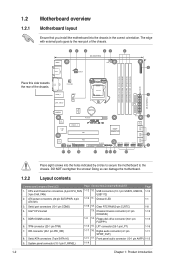
...CHA_FAN LGA1156 EATXPWR USB3_6 COM2 2 24.4cm(9.6in) LAN1_USB12 ICS 9LRS954 AUDIO RTL 8112L Super I/O PCIEX1_1 Lithium Cell CMOS Power PCIEX16 P7H55-M SI PCI1 Intel® GMA4500 SATA1 SATA2 7 8Mb BIOS 8 SATA3 SATA4 SATA5 SATA6 VIA VT1708S AAFP SPDIF_OUT LPT PCI2 17 16 15...14 13 12 11 10 Place eight screws into the chassis in the correct orientation. DO NOT overtighten the screws! Doing so can damage the motherboard. 1.2.2 Layout contents Connectors/Jumpers/Slots/LED Page Connectors/Jumpers/Slots/LED Page 1. LPT connector (26-1 pin LPT) 1-16 7. Serial ATA ...
...CHA_FAN LGA1156 EATXPWR USB3_6 COM2 2 24.4cm(9.6in) LAN1_USB12 ICS 9LRS954 AUDIO RTL 8112L Super I/O PCIEX1_1 Lithium Cell CMOS Power PCIEX16 P7H55-M SI PCI1 Intel® GMA4500 SATA1 SATA2 7 8Mb BIOS 8 SATA3 SATA4 SATA5 SATA6 VIA VT1708S AAFP SPDIF_OUT LPT PCI2 17 16 15...14 13 12 11 10 Place eight screws into the chassis in the correct orientation. DO NOT overtighten the screws! Doing so can damage the motherboard. 1.2.2 Layout contents Connectors/Jumpers/Slots/LED Page Connectors/Jumpers/Slots/LED Page 1. LPT connector (26-1 pin LPT) 1-16 7. Serial ATA ...
User Manual
Page 13
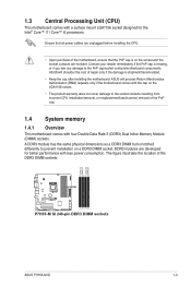
... sockets. 1.3 Central Processing Unit (CPU) This motherboard comes with less power consumption. ASUS will process Return Merchandise Authorization (RMA) requests only if the motherboard comes with the cap on the LGA1156 socket....motherboard. A DDR3 module has the same physical dimensions as a DDR3 DIMM but is on a DDR3 DIMM socket. Ensure that the PnP cap is notched differently to the PnP cap/socket contacts/motherboard components. ASUS will shoulder the cost of the DDR3 DIMM sockets: P7H55-M SI P7H55-M SI 240-pin DDR3 DIMM sockets DIMM_A2 DIMM_A1 DIMM_B2 DIMM_B1 ASUS P7H55-M SI...
... sockets. 1.3 Central Processing Unit (CPU) This motherboard comes with less power consumption. ASUS will process Return Merchandise Authorization (RMA) requests only if the motherboard comes with the cap on the LGA1156 socket....motherboard. A DDR3 module has the same physical dimensions as a DDR3 DIMM but is on a DDR3 DIMM socket. Ensure that the PnP cap is notched differently to the PnP cap/socket contacts/motherboard components. ASUS will shoulder the cost of the DDR3 DIMM sockets: P7H55-M SI P7H55-M SI 240-pin DDR3 DIMM sockets DIMM_A2 DIMM_A1 DIMM_B2 DIMM_B1 ASUS P7H55-M SI...

User Manual
Page 14
or - For effective use of memory, we recommend that you are using a 32-bit Windows® OS. - P7H55-M SI Motherboard Qualified Vendors List (QVL) DDR3-1333MHz capability Vendor Part No. AD30908C8D-151C E0906 Heat-Sink Package A-Data A-Data AD31333002GOU ...Sink Package Heat-Sink Package 9FF22D9KPT Heat-Sink Package 9KF27D9KPT Heat-Sink Package Heat-Sink Package J1108EDSE-DJ-F (continued on the motherboard. • This motherboard does not support DIMMs made up of the lower-sized channel for single-channel operation. • For dual-channel configuration,...
or - For effective use of memory, we recommend that you are using a 32-bit Windows® OS. - P7H55-M SI Motherboard Qualified Vendors List (QVL) DDR3-1333MHz capability Vendor Part No. AD30908C8D-151C E0906 Heat-Sink Package A-Data A-Data AD31333002GOU ...Sink Package Heat-Sink Package 9FF22D9KPT Heat-Sink Package 9KF27D9KPT Heat-Sink Package Heat-Sink Package J1108EDSE-DJ-F (continued on the motherboard. • This motherboard does not support DIMMs made up of the lower-sized channel for single-channel operation. • For dual-channel configuration,...

User Manual
Page 17
...an IRQ to the chassis with it by adjusting the software settings. 1. Unplug the power cord before adding or removing expansion cards. ASUS P7H55-M SI 1-7 Secure the card to the card. 3. Replace the chassis cover. 1.5.2 Configuring an expansion card After installing the expansion card, ... settings for the expansion card. The following sub-sections describe the slots and the expansion cards that you physical injury and damage motherboard components. 1.5.1 Installing an expansion card To install an expansion card: 1. 1.5 Expansion slots In the future, you may cause you...
...an IRQ to the chassis with it by adjusting the software settings. 1. Unplug the power cord before adding or removing expansion cards. ASUS P7H55-M SI 1-7 Secure the card to the card. 3. Replace the chassis cover. 1.5.2 Configuring an expansion card After installing the expansion card, ... settings for the expansion card. The following sub-sections describe the slots and the expansion cards that you physical injury and damage motherboard components. 1.5.1 Installing an expansion card To install an expansion card: 1. 1.5 Expansion slots In the future, you may cause you...

User Manual
Page 20
...USB+5V USB_P10USB_P10+ GND NC USB+5V USB_P12USB_P12+ GND NC P7H55-M SI USB1112 PIN 1 USB910 PIN 1 USB78 PIN 1 USB+5V USB_P7USB_P7+ GND USB+5V USB_P9USB_P9+ GND USB+5V USB_P11USB_P11+ GND P7H55-M SI USB2.0 connectors Never connect a 1394 cable to CRT and ...isn't compatible with DVI-I. 11. USB 2.0 ports 1 and 2. This port is for USB 2.0 ports. These four 4-pin Universal Serial Bus (USB) ports connect to support 8-channel audio output. 8. HDMI port. PS/2 Keyboard port. Doing so will damage the motherboard...
...USB+5V USB_P10USB_P10+ GND NC USB+5V USB_P12USB_P12+ GND NC P7H55-M SI USB1112 PIN 1 USB910 PIN 1 USB78 PIN 1 USB+5V USB_P7USB_P7+ GND USB+5V USB_P9USB_P9+ GND USB+5V USB_P11USB_P11+ GND P7H55-M SI USB2.0 connectors Never connect a 1394 cable to CRT and ...isn't compatible with DVI-I. 11. USB 2.0 ports 1 and 2. This port is for USB 2.0 ports. These four 4-pin Universal Serial Bus (USB) ports connect to support 8-channel audio output. 8. HDMI port. PS/2 Keyboard port. Doing so will damage the motherboard...

User Manual
Page 22
... cables to use the chassis intrusion detection feature. +5VSB_MB Chassis Signal GND P7H55-M SI CHASSIS P7H55-M SI Chassis intrusion connector 1-12 Chapter 1: Product introduction Insufficient air flow inside the system may damage the motherboard components. DO NOT place jumper caps on the motherboard, making sure that the black wire of each cable matches the ground pin...
... cables to use the chassis intrusion detection feature. +5VSB_MB Chassis Signal GND P7H55-M SI CHASSIS P7H55-M SI Chassis intrusion connector 1-12 Chapter 1: Product introduction Insufficient air flow inside the system may damage the motherboard components. DO NOT place jumper caps on the motherboard, making sure that the black wire of each cable matches the ground pin...
User Manual
Page 27
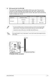
... for Ultra DMA 133/100 IDE devices. Connect the blue connector to the motherboard's IDE connector, then select one of the following modes to match the covered hole on the Ultra DMA cable connector. P7H55-M SI IDE connector ASUS P7H55-M SI 1-17 IDE connector (40-1 pin PRI_IDE) The onboard IDE connector is set... insertion when you connect the IDE cable. • Use the 80-conductor IDE cable for Ultra DMA 133/100 signal cable. PRI_IDE PIN1 P7H55-M SI NOTE:Orient the red markings on each Ultra DMA 133/100 signal cable: blue, black, and gray. 13. There are three connectors on...
... for Ultra DMA 133/100 IDE devices. Connect the blue connector to the motherboard's IDE connector, then select one of the following modes to match the covered hole on the Ultra DMA cable connector. P7H55-M SI IDE connector ASUS P7H55-M SI 1-17 IDE connector (40-1 pin PRI_IDE) The onboard IDE connector is set... insertion when you connect the IDE cable. • Use the 80-conductor IDE cable for Ultra DMA 133/100 signal cable. PRI_IDE PIN1 P7H55-M SI NOTE:Orient the red markings on each Ultra DMA 133/100 signal cable: blue, black, and gray. 13. There are three connectors on...

User Manual
Page 29
...From the dropdown list, select any of the original motherboard BIOS file to a USB flash disk in case you need to manage, save, and update the motherboard BIOS in Windows® environment. • ASUS Update requires an Internet connection either through a network or... you update the BIOS using the ASUS Update utility. 2.1.1 ASUS Update utility The ASUS Update is a utility that comes with the motherboard package. Chapter 2 BIOS information 2.1 Managing and updating your BIOS Save a copy of the updating process: ASUS P7H55-M SI 2-1 Installing ASUS Update To install ASUS Update: 1.
...From the dropdown list, select any of the original motherboard BIOS file to a USB flash disk in case you need to manage, save, and update the motherboard BIOS in Windows® environment. • ASUS Update requires an Internet connection either through a network or... you update the BIOS using the ASUS Update utility. 2.1.1 ASUS Update utility The ASUS Update is a utility that comes with the motherboard package. Chapter 2 BIOS information 2.1 Managing and updating your BIOS Save a copy of the updating process: ASUS P7H55-M SI 2-1 Installing ASUS Update To install ASUS Update: 1.

User Manual
Page 31
Prepare the motherboard support DVD and a USB flash drive in DOS environment 1. Insert the support DVD into the optical drive and select the optical drive as shown. 2. When ... 2 utility. • Do not shut down or reset the system while updating the BIOS to prevent system boot failure! 2.1.3 ASUS BIOS Updater The ASUS BIOS Updater allows you to boot using defaults ASUS P7H55-M SI 2-3 The actual utility screen displays may not be same as the boot device. Turn off the computer and disconnect all...
Prepare the motherboard support DVD and a USB flash drive in DOS environment 1. Insert the support DVD into the optical drive and select the optical drive as shown. 2. When ... 2 utility. • Do not shut down or reset the system while updating the BIOS to prevent system boot failure! 2.1.3 ASUS BIOS Updater The ASUS BIOS Updater allows you to boot using defaults ASUS P7H55-M SI 2-3 The actual utility screen displays may not be same as the boot device. Turn off the computer and disconnect all...

User Manual
Page 35
... program. 2.2 BIOS setup program Use the BIOS Setup program to download the latest BIOS file for this motherboard. Entering BIOS Setup at startup To enter BIOS Setup at www.asus.com to update the BIOS or configure its routines. See section 2.8 Exit Menu. • The BIOS...; Press ++ simultaneously. • Press the reset button on your data or system. Select the Load Setups Default item under the Exit Menu. ASUS P7H55-M SI 2-7 If you see on the system chassis. • Press the power button to ensure optimum performance. Do this section are for reference purposes ...
... program. 2.2 BIOS setup program Use the BIOS Setup program to download the latest BIOS file for this motherboard. Entering BIOS Setup at startup To enter BIOS Setup at www.asus.com to update the BIOS or configure its routines. See section 2.8 Exit Menu. • The BIOS...; Press ++ simultaneously. • Press the reset button on your data or system. Select the Load Setups Default item under the Exit Menu. ASUS P7H55-M SI 2-7 If you see on the system chassis. • Press the power button to ensure optimum performance. Do this section are for reference purposes ...
User Manual
Page 43
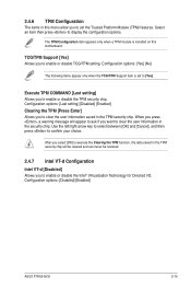
...] [Enabled] Clearing the TPM [Press Enter] Allows you to set to enable or disable the Intel® Virtualization Technology for Directed I/O. Configuration options: [Disabled] [Enabled] ASUS P7H55-M SI 2-15 Execute TPM COMMAND [Last setting] Allows you to enable or disable the TPM security chip. TCG/TPM Support [Yes] Allows you to enable or... the TPM function, the data saved in the TPM security chip will appear to ask if you to [Yes]. 2.4.6 TPM Configuration The items in this motherboard.
...] [Enabled] Clearing the TPM [Press Enter] Allows you to set to enable or disable the Intel® Virtualization Technology for Directed I/O. Configuration options: [Disabled] [Enabled] ASUS P7H55-M SI 2-15 Execute TPM COMMAND [Last setting] Allows you to enable or disable the TPM security chip. TCG/TPM Support [Yes] Allows you to enable or... the TPM function, the data saved in the TPM security chip will appear to ask if you to [Yes]. 2.4.6 TPM Configuration The items in this motherboard.

User Manual
Page 45
... fan is in rotations per minute (RPM). ASUS P7H55-M SI 2-17 Select Ignored if you do not wish to enable or disable the CPU Q-Fan control. CPU Q-Fan Control [Enabled] Allows you to display the detected speed. Select Ignored if you do not wish to the motherboard, the field shows N/A. This feature requires an...
... fan is in rotations per minute (RPM). ASUS P7H55-M SI 2-17 Select Ignored if you do not wish to enable or disable the CPU Q-Fan control. CPU Q-Fan Control [Enabled] Allows you to display the detected speed. Select Ignored if you do not wish to the motherboard, the field shows N/A. This feature requires an...


