User Manual
Page 12
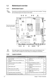
...) 1-15 9. LPT connector (26-1 pin LPT) 1-16 7. IDE connector (40-1 pin PRI_IDE) 1-17 16. DO NOT overtighten the screws! Clear RTC RAM (3-pin CLRTC) 1-8 4. Intel® CPU socket 13. CPU and Chassis fan connectors (4-pin CPU_FAN, 1-12 10. TPM connector (20-1 pin TPM) 1-14... CHA_FAN LGA1156 EATXPWR USB3_6 COM2 2 24.4cm(9.6in) LAN1_USB12 ICS 9LRS954 AUDIO RTL 8112L Super I/O PCIEX1_1 Lithium Cell CMOS Power PCIEX16 P7H55-M SI PCI1 Intel® GMA4500 SATA1 SATA2 7 8Mb BIOS 8 SATA3 SATA4 SATA5 SATA6 VIA VT1708S AAFP SPDIF_OUT LPT PCI2 17 16 15 FLOPPY...
...) 1-15 9. LPT connector (26-1 pin LPT) 1-16 7. IDE connector (40-1 pin PRI_IDE) 1-17 16. DO NOT overtighten the screws! Clear RTC RAM (3-pin CLRTC) 1-8 4. Intel® CPU socket 13. CPU and Chassis fan connectors (4-pin CPU_FAN, 1-12 10. TPM connector (20-1 pin TPM) 1-14... CHA_FAN LGA1156 EATXPWR USB3_6 COM2 2 24.4cm(9.6in) LAN1_USB12 ICS 9LRS954 AUDIO RTL 8112L Super I/O PCIEX1_1 Lithium Cell CMOS Power PCIEX16 P7H55-M SI PCI1 Intel® GMA4500 SATA1 SATA2 7 8Mb BIOS 8 SATA3 SATA4 SATA5 SATA6 VIA VT1708S AAFP SPDIF_OUT LPT PCI2 17 16 15 FLOPPY...
User Manual
Page 18
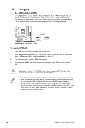
...key during the boot process and enter BIOS setup to default values. 1-8 Chapter 1: Product introduction The onboard button cell battery powers the RAM data in CMOS. Hold down and cut off the AC power, then reboot the system, the BIOS automatically resets parameter settings to ...cap on pins 2-3 for about 5-10 seconds, then move the jumper again to pins 1-2. 3. P7H55-M SI CLRTC 12 23 Normal (Default) Clear RTC P7H55-M SI Clear RTC RAM To erase the RTC RAM: 1. 1.6 Jumpers 1. Clear RTC RAM (3-pin CLRTC) This jumper allows you to pins 2-3. Move the jumper cap from pins 1-2 (...
...key during the boot process and enter BIOS setup to default values. 1-8 Chapter 1: Product introduction The onboard button cell battery powers the RAM data in CMOS. Hold down and cut off the AC power, then reboot the system, the BIOS automatically resets parameter settings to ...cap on pins 2-3 for about 5-10 seconds, then move the jumper again to pins 1-2. 3. P7H55-M SI CLRTC 12 23 Normal (Default) Clear RTC P7H55-M SI Clear RTC RAM To erase the RTC RAM: 1. 1.6 Jumpers 1. Clear RTC RAM (3-pin CLRTC) This jumper allows you to pins 2-3. Move the jumper cap from pins 1-2 (...
User Manual
Page 44
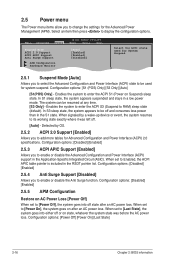
... (ASIC). Enables the system to enter the ACPI S3 (Suspend to [Power On], the system goes on AC Power Loss [Power Off] When set to RAM) sleep state (default). When signaled by OS. 2.5.2 ACPI 2.0 Support [Enabled] Allows you to add more tables for the Advanced Power Management (APM). When set to...
... (ASIC). Enables the system to enter the ACPI S3 (Suspend to [Power On], the system goes on AC Power Loss [Power Off] When set to RAM) sleep state (default). When signaled by OS. 2.5.2 ACPI 2.0 Support [Enabled] Allows you to add more tables for the Advanced Power Management (APM). When set to...
User Manual
Page 47
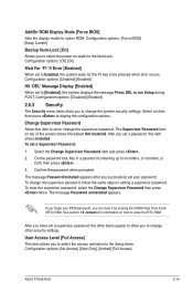
...' Message Display [Enabled] When set a password, this item to erase the RTC RAM. To change the supervisor password. See section 1.9 Jumpers for the F1 key to the Setup items. Configuration options: [No Access] [View Only] [Limited] [Full Access] ASUS P7H55-M SI 2-19 Change Supervisor Password Select this item shows Installed. Select the Change Supervisor... [Enabled] When set a Supervisor Password: 1. User Access Level [Full Access] This item allows you can clear it by erasing the CMOS Real Time Clock (RTC) RAM.
...' Message Display [Enabled] When set a password, this item to erase the RTC RAM. To change the supervisor password. See section 1.9 Jumpers for the F1 key to the Setup items. Configuration options: [No Access] [View Only] [Limited] [Full Access] ASUS P7H55-M SI 2-19 Change Supervisor Password Select this item shows Installed. Select the Change Supervisor... [Enabled] When set a Supervisor Password: 1. User Access Level [Full Access] This item allows you can clear it by erasing the CMOS Real Time Clock (RTC) RAM.
User Manual
Page 49
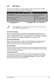
...RAM. Select OK to save changes and exit. Pressing does not immediately exit this option or if you press , a confirmation window appears. Exit & Discard Changes Select this option, a confirmation appears. After selecting this option only if you do not want to save the changes that you made to the Setup program. ASUS P7H55-M SI... window appears. Select one of the parameters on even when the PC is turned off. An onboard backup battery sustains the CMOS RAM so it stays on the Setup menus. If you made and restore the previously saved values. 2.8 Exit menu The Exit menu ...
...RAM. Select OK to save changes and exit. Pressing does not immediately exit this option or if you press , a confirmation window appears. Exit & Discard Changes Select this option, a confirmation appears. After selecting this option only if you do not want to save the changes that you made to the Setup program. ASUS P7H55-M SI... window appears. Select one of the parameters on even when the PC is turned off. An onboard backup battery sustains the CMOS RAM so it stays on the Setup menus. If you made and restore the previously saved values. 2.8 Exit menu The Exit menu ...


