User Manual
Page 11
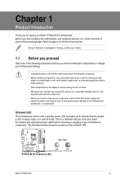
...on it on them. • Whenever you uninstall any motherboard component. Failure to do so may cause severe damage to page ix for buying an ASUS® P7H55-M SI motherboard! Refer to the motherboard, peripherals, or components. Chapter 1 Product introduction Thank you for the list of accessories. If any of the items ...package. The illustration below shows the location of the following precautions before you install motherboard components or change any component, switch off mode. SB_PWR P7H55-M SI ON OFF Standby Power Powered Off P7H55-M SI Onboard LED ASUS P7H55-M SI 1-1
...on it on them. • Whenever you uninstall any motherboard component. Failure to do so may cause severe damage to page ix for buying an ASUS® P7H55-M SI motherboard! Refer to the motherboard, peripherals, or components. Chapter 1 Product introduction Thank you for the list of accessories. If any of the items ...package. The illustration below shows the location of the following precautions before you install motherboard components or change any component, switch off mode. SB_PWR P7H55-M SI ON OFF Standby Power Powered Off P7H55-M SI Onboard LED ASUS P7H55-M SI 1-1
User Manual
Page 13
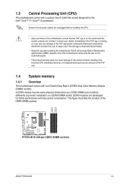
...repair only if the damage is notched differently to prevent installation on the socket and the socket contacts are not bent. ASUS will process Return Merchandise Authorization (RMA) requests only if the motherboard comes with the cap on the LGA1156 socket. ...but is shipment/transit-related. • Keep the cap after installing the motherboard. ASUS will shoulder the cost of the DDR3 DIMM sockets: P7H55-M SI P7H55-M SI 240-pin DDR3 DIMM sockets DIMM_A2 DIMM_A1 DIMM_B2 DIMM_B1 ASUS P7H55-M SI 1-3 1.3 Central Processing Unit (CPU) This motherboard comes with four Double Data Rate...
...repair only if the damage is notched differently to prevent installation on the socket and the socket contacts are not bent. ASUS will process Return Merchandise Authorization (RMA) requests only if the motherboard comes with the cap on the LGA1156 socket. ...but is shipment/transit-related. • Keep the cap after installing the motherboard. ASUS will shoulder the cost of the DDR3 DIMM sockets: P7H55-M SI P7H55-M SI 240-pin DDR3 DIMM sockets DIMM_A2 DIMM_A1 DIMM_B2 DIMM_B1 ASUS P7H55-M SI 1-3 1.3 Central Processing Unit (CPU) This motherboard comes with four Double Data Rate...
User Manual
Page 15
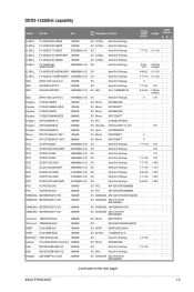
...-Sink Package - - • •• Kingtiger 2GB DIMM PC3-10666 2048MB DS SAMSUNG SEC 904 HCH9 K4B1G0846D - - • •• (continued on the next page) ASUS P7H55-M SI 1-5 DDR3-1333MHz capability Vendor Part No. Heat-Sink Package 7-7-7-18 1.5~1.6V • • • G.SKILL F3-10600CL7D-2GBPI(XMP) 1024MB DS G.SKILL Heat-Sink Package...
...-Sink Package - - • •• Kingtiger 2GB DIMM PC3-10666 2048MB DS SAMSUNG SEC 904 HCH9 K4B1G0846D - - • •• (continued on the next page) ASUS P7H55-M SI 1-5 DDR3-1333MHz capability Vendor Part No. Heat-Sink Package 7-7-7-18 1.5~1.6V • • • G.SKILL F3-10600CL7D-2GBPI(XMP) 1024MB DS G.SKILL Heat-Sink Package...

User Manual
Page 17
... for the card. 2. Assign an IRQ to install expansion cards. Remove the bracket opposite the slot that they support. See Chapter 2 for the expansion card. ASUS P7H55-M SI 1-7 When using PCI cards on the slot. 5. 1.5 Expansion slots In the future, you may cause you intend to use. 4. Install the software drivers for information...
... for the card. 2. Assign an IRQ to install expansion cards. Remove the bracket opposite the slot that they support. See Chapter 2 for the expansion card. ASUS P7H55-M SI 1-7 When using PCI cards on the slot. 5. 1.5 Expansion slots In the future, you may cause you intend to use. 4. Install the software drivers for information...
User Manual
Page 19
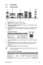
... Speaker Out Mic In - 6-channel Rear Speaker Out Front Speaker Out Bass/Center - 8-channel Rear Speaker Out Front Speaker Out Bass/Center Side Speaker Out ASUS P7H55-M SI 1-9 In 4-channel, 6-channel, and 8-channel configurations, the function of the audio ports in the 2, 4, 6, or 8-channel configuration. 1.7 Connectors 1.7.1 Rear panel ports 1 2 3 4 56 12 11 10...
... Speaker Out Mic In - 6-channel Rear Speaker Out Front Speaker Out Bass/Center - 8-channel Rear Speaker Out Front Speaker Out Bass/Center Side Speaker Out ASUS P7H55-M SI 1-9 In 4-channel, 6-channel, and 8-channel configurations, the function of the audio ports in the 2, 4, 6, or 8-channel configuration. 1.7 Connectors 1.7.1 Rear panel ports 1 2 3 4 56 12 11 10...

User Manual
Page 21
...RSATA_TXP1 RSATA_TXN1 GND RSATA_RXP1 RSATA_RXN1 GND SATA3 GND RSATA_TXP3 RSATA_TXN3 GND RSATA_RXP3 RSATA_RXN3 GND P7H55-M SI SATA5 GND RSATA_TXP5 RSATA_TXN5 GND RSATA_RXP5 RSATA_RXN5 GND P7H55-M SI SATA connectors GND RSATA_TXP2 RSATA_TXN2 GND RSATA_RXP2 RSATA_RXN2 GND GND RSATA_TXP4 RSATA_TXN4 GND RSATA_RXP4...Philips Digital Interface (S/PDIF) port. +5V SPDIFOUT GND P7H55-M SI SPDIF_OUT P7H55-M SI Digital audio connector The S/PDIF module is faster than the standard parallel ATA with Serial ATA 1.5Gb/s specification. ASUS P7H55-M SI 1-11 2. The Serial ATA 3Gb/s is for Serial ...
...RSATA_TXP1 RSATA_TXN1 GND RSATA_RXP1 RSATA_RXN1 GND SATA3 GND RSATA_TXP3 RSATA_TXN3 GND RSATA_RXP3 RSATA_RXN3 GND P7H55-M SI SATA5 GND RSATA_TXP5 RSATA_TXN5 GND RSATA_RXP5 RSATA_RXN5 GND P7H55-M SI SATA connectors GND RSATA_TXP2 RSATA_TXN2 GND RSATA_RXP2 RSATA_RXN2 GND GND RSATA_TXP4 RSATA_TXN4 GND RSATA_RXP4...Philips Digital Interface (S/PDIF) port. +5V SPDIFOUT GND P7H55-M SI SPDIF_OUT P7H55-M SI Digital audio connector The S/PDIF module is faster than the standard parallel ATA with Serial ATA 1.5Gb/s specification. ASUS P7H55-M SI 1-11 2. The Serial ATA 3Gb/s is for Serial ...
User Manual
Page 23
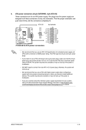
... boot up if the power is inadequate. • If you use a PSU with a minimum of 300 W. ATX12V EATXPWR +12V DC +12V DC P7H55-M SI GND GND +3 Volts +12 Volts +12 Volts +5V Standby Power OK PIN 1 GND +5 Volts GND +5 Volts GND +3 Volts +3 Volts PIN... rating of 300W power rating. com/PowerSupplyCalculator/PSCalculator.aspx?SLanguage=en-us for your system, refer to fit these connectors in only one orientation. ASUS P7H55-M SI 1-13 The plugs from the power supply are for an ATX power supply. ATX power connectors (24-pin EATXPWR, 4-pin ATX12V) These connectors...
... boot up if the power is inadequate. • If you use a PSU with a minimum of 300 W. ATX12V EATXPWR +12V DC +12V DC P7H55-M SI GND GND +3 Volts +12 Volts +12 Volts +5V Standby Power OK PIN 1 GND +5 Volts GND +5 Volts GND +3 Volts +3 Volts PIN... rating of 300W power rating. com/PowerSupplyCalculator/PSCalculator.aspx?SLanguage=en-us for your system, refer to fit these connectors in only one orientation. ASUS P7H55-M SI 1-13 The plugs from the power supply are for an ATX power supply. ATX power connectors (24-pin EATXPWR, 4-pin ATX12V) These connectors...
User Manual
Page 25
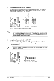
... want to connect an AC97 front panel audio module to this connector, ensure that supports either High Definition Audio or AC`97 audio standard. FLOPPY P7H55-M SI PIN1 NOTE:Orient the red markings on the connector is for details. 10. AGND NC SENSE1_RETUR SENSE2_RETUR AGND NC NC NC AAFP PIN 1 PIN 1 MIC2... BIOS is for the floppy disk drive (FDD) signal cable. Floppy disk drive connector (34-1 pin FLOPPY) This connector is set the item to PIN 1. P7H55-M SI Floppy disk drive connector ASUS P7H55-M SI 1-15 9.
... want to connect an AC97 front panel audio module to this connector, ensure that supports either High Definition Audio or AC`97 audio standard. FLOPPY P7H55-M SI PIN1 NOTE:Orient the red markings on the connector is for details. 10. AGND NC SENSE1_RETUR SENSE2_RETUR AGND NC NC NC AAFP PIN 1 PIN 1 MIC2... BIOS is for the floppy disk drive (FDD) signal cable. Floppy disk drive connector (34-1 pin FLOPPY) This connector is set the item to PIN 1. P7H55-M SI Floppy disk drive connector ASUS P7H55-M SI 1-15 9.
User Manual
Page 27
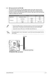
... Ultra DMA cable connector. Connect the blue connector to the motherboard's IDE connector, then select one of the following modes to PIN 1. P7H55-M SI IDE connector ASUS P7H55-M SI 1-17 PRI_IDE PIN1 P7H55-M SI NOTE:Orient the red markings on each Ultra DMA 133/100 signal cable: blue, black, and gray. There are three connectors on the...
... Ultra DMA cable connector. Connect the blue connector to the motherboard's IDE connector, then select one of the following modes to PIN 1. P7H55-M SI IDE connector ASUS P7H55-M SI 1-17 PRI_IDE PIN1 P7H55-M SI NOTE:Orient the red markings on each Ultra DMA 133/100 signal cable: blue, black, and gray. There are three connectors on the...

User Manual
Page 29
...Quit all Windows® applications before you need to restore the BIOS in case you update the BIOS using the ASUS Update utility. 2.1.1 ASUS Update utility The ASUS Update is a utility that allows you to a USB flash disk in the future. From the dropdown list, ... • This utility is available in the optical drive. Installing ASUS Update To install ASUS Update: 1. The Drivers menu appears. 2. Chapter 2 BIOS information 2.1 Managing and updating your BIOS Save a copy of the updating process: ASUS P7H55-M SI 2-1 Copy the original motherboard BIOS using this utility. From the ...
...Quit all Windows® applications before you need to restore the BIOS in case you update the BIOS using the ASUS Update utility. 2.1.1 ASUS Update utility The ASUS Update is a utility that allows you to a USB flash disk in the future. From the dropdown list, ... • This utility is available in the optical drive. Installing ASUS Update To install ASUS Update: 1. The Drivers menu appears. 2. Chapter 2 BIOS information 2.1 Managing and updating your BIOS Save a copy of the updating process: ASUS P7H55-M SI 2-1 Copy the original motherboard BIOS using this utility. From the ...

User Manual
Page 31
... the correct BIOS file is not supported under DOS environment. Download the latest BIOS file and BIOS Updater from the ASUS website at http:// support.asus.com and save the BIOS file to a floppy disk due to update BIOS in NTFS format. • Do not...as the boot device. Prepare the motherboard support DVD and a USB flash drive in DOS environment 1. When the ASUS Logo appears, press to boot using defaults ASUS P7H55-M SI 2-3 The succeeding utility screens are for reference only. Please select boot device: SATA:XXXXXXXXXXXXXXXX CDROM:XXXXXXXXXXXXXXX USB:XXXXXXXXXXXXXXXXX...
... the correct BIOS file is not supported under DOS environment. Download the latest BIOS file and BIOS Updater from the ASUS website at http:// support.asus.com and save the BIOS file to a floppy disk due to update BIOS in NTFS format. • Do not...as the boot device. Prepare the motherboard support DVD and a USB flash drive in DOS environment 1. When the ASUS Logo appears, press to boot using defaults ASUS P7H55-M SI 2-3 The succeeding utility screens are for reference only. Please select boot device: SATA:XXXXXXXXXXXXXXXX CDROM:XXXXXXXXXXXXXXX USB:XXXXXXXXXXXXXXXXX...

User Manual
Page 33
... to update BIOS? Restart your computer. See section 2.8 Exit menu for DOS V1.00b [09/06/22] FLASH TYPE: Winbond 25X/Q64 Current ROM BOARD: P7H55-M SI VER: 0207 DATE: 12/14/2009 Update ROM BOARD: Unknown VER: Unknown DATE: Unknown PATH: A:\ A: P7H55M.ROM 2097152 2009-12-14 17:30:48 Note... file and prompts you sure to ensure system compatibility and stability. When BIOS update is done, press to confirm BIOS update. Select Yes and press . ASUS P7H55-M SI 2-5 The BIOS Updater screen appears as below. Yes No 4.
... to update BIOS? Restart your computer. See section 2.8 Exit menu for DOS V1.00b [09/06/22] FLASH TYPE: Winbond 25X/Q64 Current ROM BOARD: P7H55-M SI VER: 0207 DATE: 12/14/2009 Update ROM BOARD: Unknown VER: Unknown DATE: Unknown PATH: A:\ A: P7H55M.ROM 2097152 2009-12-14 17:30:48 Note... file and prompts you sure to ensure system compatibility and stability. When BIOS update is done, press to confirm BIOS update. Select Yes and press . ASUS P7H55-M SI 2-5 The BIOS Updater screen appears as below. Yes No 4.

User Manual
Page 35
...performance. We recommend to always shut down the system properly from a running operating system can cause damage to your screen. • Visit the ASUS website at startup: • Press during the Power-On Self Test (POST). Select the Load Setups Default item under the Exit Menu. ... reset button on the system chassis. • Press the power button to turn the system off then back on your data or system. ASUS P7H55-M SI 2-7 2.2 BIOS setup program Use the BIOS Setup program to update the BIOS or configure its routines. The BIOS screens include navigation keys and...
...performance. We recommend to always shut down the system properly from a running operating system can cause damage to your screen. • Visit the ASUS website at startup: • Press during the Power-On Self Test (POST). Select the Load Setups Default item under the Exit Menu. ... reset button on the system chassis. • Press the power button to turn the system off then back on your data or system. ASUS P7H55-M SI 2-7 2.2 BIOS setup program Use the BIOS Setup program to update the BIOS or configure its routines. The BIOS screens include navigation keys and...
User Manual
Page 37
... for detecting ATA/ATAPI devices. This will be effective only if device is not supported in driver. Configuration options: [0] [5] [10] [15] [20] [25] [30] [35] ASUS P7H55-M SI 2-9 Select an item then press if you to Intel chipset driver support regulation, the AHCI mode is accessed through BIOS. Configuration option: [Disabled] [Enabled] IDE...
... for detecting ATA/ATAPI devices. This will be effective only if device is not supported in driver. Configuration options: [0] [5] [10] [15] [20] [25] [30] [35] ASUS P7H55-M SI 2-9 Select an item then press if you to Intel chipset driver support regulation, the AHCI mode is accessed through BIOS. Configuration option: [Disabled] [Enabled] IDE...

User Manual
Page 39
... [Enabled] When this item is controlled by making the next cache line immediately available if the processor requires it as well. Configuration options: [Enabled] [Disabled] ASUS P7H55-M SI 2-11 Configuration options: [Disabled] [Enabled] Max CPUID Value Limit [Disabled] Setting this item to [Enabled] allows legacy operating systems to be required in each processor...
... [Enabled] When this item is controlled by making the next cache line immediately available if the processor requires it as well. Configuration options: [Enabled] [Disabled] ASUS P7H55-M SI 2-11 Configuration options: [Disabled] [Enabled] Max CPUID Value Limit [Disabled] Setting this item to [Enabled] allows legacy operating systems to be required in each processor...
User Manual
Page 41
... you to select the Parallel Port base addresses. Configuration options: [Disabled] [Enabled] Serial Port1 Address [3F8/IRQ4] Allows you to [ECP]. Configuration options: [IRQ5] [IRQ7] ASUS P7H55-M SI 2-13
... you to select the Parallel Port base addresses. Configuration options: [Disabled] [Enabled] Serial Port1 Address [3F8/IRQ4] Allows you to [ECP]. Configuration options: [IRQ5] [IRQ7] ASUS P7H55-M SI 2-13
User Manual
Page 43
... to confirm your choice. The TPM Configuration item appears only when a TPM module is set the Trusted Platform Module (TPM) features. Configuration options: [Disabled] [Enabled] ASUS P7H55-M SI 2-15 Use the left/right arrow key to select between [OK] and [Cancel], and then press to enable or disable the TPM security chip. Configuration...
... to confirm your choice. The TPM Configuration item appears only when a TPM module is set the Trusted Platform Module (TPM) features. Configuration options: [Disabled] [Enabled] ASUS P7H55-M SI 2-15 Use the left/right arrow key to select between [OK] and [Cancel], and then press to enable or disable the TPM security chip. Configuration...

User Manual
Page 45
... PCIE Devices [Disabled] When set values. When this parameter allows you to turn on the PS/2 keyboard to wake the system through a PCI Express card. ASUS P7H55-M SI 2-17 Configuration options: [Disabled] [Enabled] Power On By PS/2 Keyboard [Disabled] Allows you to use the PS/2 mouse to [Enabled], this item is in rotations...
... PCIE Devices [Disabled] When set values. When this parameter allows you to turn on the PS/2 keyboard to wake the system through a PCI Express card. ASUS P7H55-M SI 2-17 Configuration options: [Disabled] [Enabled] Power On By PS/2 Keyboard [Disabled] Allows you to use the PS/2 mouse to [Enabled], this item is in rotations...
User Manual
Page 47
... Display Mode [Force BIOS] Sets the display mode for the F1 key to the Setup items. Configuration options: [No Access] [View Only] [Limited] [Full Access] ASUS P7H55-M SI 2-19 Select the Change Supervisor Password item and press . 2. Configuration options: [Disabled] [Enabled] Hit 'DEL' Message Display [Enabled] When set to Enabled, the system waits...
... Display Mode [Force BIOS] Sets the display mode for the F1 key to the Setup items. Configuration options: [No Access] [View Only] [Limited] [Full Access] ASUS P7H55-M SI 2-19 Select the Change Supervisor Password item and press . 2. Configuration options: [Disabled] [Enabled] Hit 'DEL' Message Display [Enabled] When set to Enabled, the system waits...
User Manual
Page 49
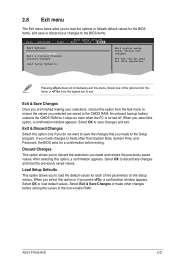
... a confirmation before saving the values to the non-volatile RAM. Discard Changes This option allows you to discard the selections you press , a confirmation window appears. ASUS P7H55-M SI 2-21 If you made and restore the previously saved values. Exit & Save Changes Once you are saved to the CMOS RAM. An onboard backup battery...
... a confirmation before saving the values to the non-volatile RAM. Discard Changes This option allows you to discard the selections you press , a confirmation window appears. ASUS P7H55-M SI 2-21 If you made and restore the previously saved values. Exit & Save Changes Once you are saved to the CMOS RAM. An onboard backup battery...


