User Manual
Page 10
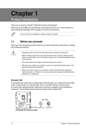
... • Hold components by the edges to the motherboard, peripherals, or components. SB_PWR P7H55-M LE ON OFF Standby Power Powered Off P7H55-M LE Onboard LED 1-1 Chapter 1: Product introduction This is a reminder that lights up to page ix for buying an ASUS® P7H55-M LE Series motherboard! The illustration below shows the location of the following precautions before...
... • Hold components by the edges to the motherboard, peripherals, or components. SB_PWR P7H55-M LE ON OFF Standby Power Powered Off P7H55-M LE Onboard LED 1-1 Chapter 1: Product introduction This is a reminder that lights up to page ix for buying an ASUS® P7H55-M LE Series motherboard! The illustration below shows the location of the following precautions before...
User Manual
Page 11
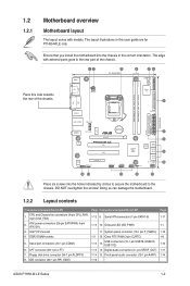
...SATA1-6) 1-13 10. Onboard LED (SB_PWR) 11. KBMS 12 3 21.8cm(8.6in) 4 56 COM2 COM1 Place this user guide are for P7H55-M LE only. LPT connector (26-1 pin LPT) 7. IDE connector (40-1 pin PRI_EIDE) Page Connectors/Jumpers/Slots/LED 1-12 9. 1.2 1.2.1 Motherboard ... layout illustrations in the correct orientation. Front panel audio connector (10-1 pin AAFP) 1-16 Page 1-11 1-1 1-12 1-8 1-10 1-11 1-14 ASUS P7H55-M LE Series 1-2 USB connectors (10-1 pin USB78, USB910, USB1112) 1-15 14. Digital audio connector (4-1 pin SPDIF_OUT) 1-14 15. Ensure that you ...
...SATA1-6) 1-13 10. Onboard LED (SB_PWR) 11. KBMS 12 3 21.8cm(8.6in) 4 56 COM2 COM1 Place this user guide are for P7H55-M LE only. LPT connector (26-1 pin LPT) 7. IDE connector (40-1 pin PRI_EIDE) Page Connectors/Jumpers/Slots/LED 1-12 9. 1.2 1.2.1 Motherboard ... layout illustrations in the correct orientation. Front panel audio connector (10-1 pin AAFP) 1-16 Page 1-11 1-1 1-12 1-8 1-10 1-11 1-14 ASUS P7H55-M LE Series 1-2 USB connectors (10-1 pin USB78, USB910, USB1112) 1-15 14. Digital audio connector (4-1 pin SPDIF_OUT) 1-14 15. Ensure that you ...
User Manual
Page 13
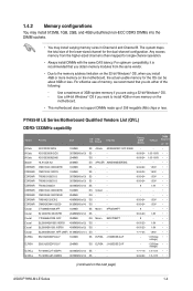
... or less. The system maps the total size of memory, we recommend that you install 4GB or more memory on the next page) ASUS P7H55-M LE Series 1-4 1.4.2 Memory configurations You may install 512MB, 1GB, 2GB, and 4GB unbuffered non-ECC DDR3 DIMMs into the DIMM sockets. &#...8226; You may install varying memory sizes in Channel A and Channel B. P7H55-M LE Series Motherboard Qualified Vendors List (QVL) DDR3-1333MHz capability Vendor A-Data A-Data A-Data Apacer CORSAIR CORSAIR CORSAIR CORSAIR CORSAIR CORSAIR CORSAIR CORSAIR ...
... or less. The system maps the total size of memory, we recommend that you install 4GB or more memory on the next page) ASUS P7H55-M LE Series 1-4 1.4.2 Memory configurations You may install 512MB, 1GB, 2GB, and 4GB unbuffered non-ECC DDR3 DIMMs into the DIMM sockets. &#...8226; You may install varying memory sizes in Channel A and Channel B. P7H55-M LE Series Motherboard Qualified Vendors List (QVL) DDR3-1333MHz capability Vendor A-Data A-Data A-Data Apacer CORSAIR CORSAIR CORSAIR CORSAIR CORSAIR CORSAIR CORSAIR CORSAIR ...
User Manual
Page 15
... 2048MB 1024MB 512MB 512MB 1024MB 2048MB 1024MB 2048MB 4096MB 1024MB 2048MB 1024MB 4096MB 2048MB 2048MB 2048MB 2048MB SS/ DS Chip Brand Chip No. Visit the ASUS website at www.asus.com for the latest QVL. Double - ASUS P7H55-M LE Series 1-6
... 2048MB 1024MB 512MB 512MB 1024MB 2048MB 1024MB 2048MB 4096MB 1024MB 2048MB 1024MB 4096MB 2048MB 2048MB 2048MB 2048MB SS/ DS Chip Brand Chip No. Visit the ASUS website at www.asus.com for the latest QVL. Double - ASUS P7H55-M LE Series 1-6
User Manual
Page 17
... of date, time, and system setup parameters by erasing the CMOS RTC RAM data. P7H55-M LE CLRTC 12 23 Normal (Default) Clear RTC P7H55-M LE Clear RTC RAM To erase the RTC RAM: 1. Hold down and cut off the AC power, then reboot the system, the BIOS automatically resets parameter settings to pins 2-3. ASUS P7H55-M LE Series 1-8
... of date, time, and system setup parameters by erasing the CMOS RTC RAM data. P7H55-M LE CLRTC 12 23 Normal (Default) Clear RTC P7H55-M LE Clear RTC RAM To erase the RTC RAM: 1. Hold down and cut off the AC power, then reboot the system, the BIOS automatically resets parameter settings to pins 2-3. ASUS P7H55-M LE Series 1-8
User Manual
Page 19
...This port is HDCP compliant allowing playback of the system chassis. This is a High-Definition Mulltimedia Interface (HDMI) connector, and is for P7H55-M LE and P7H55-M LX only). These two 4-pin Universal Serial Bus (USB) ports connect to USB 2.0/1.1 devices. 10. Connect the USB module cable...install the module to a slot opening at the back of HD DVD, Blu-Ray, and other protected content. 12. PS/2 Keyboard port. ASUS P7H55-M LE Series 1-10 USB connectors (10-1 pin USB78, USB910, USB1112) These connectors are for a PS/2 keyboard. 1.7.2 Internal connectors 1. This port ...
...This port is HDCP compliant allowing playback of the system chassis. This is a High-Definition Mulltimedia Interface (HDMI) connector, and is for P7H55-M LE and P7H55-M LX only). These two 4-pin Universal Serial Bus (USB) ports connect to USB 2.0/1.1 devices. 10. Connect the USB module cable...install the module to a slot opening at the back of HD DVD, Blu-Ray, and other protected content. 12. PS/2 Keyboard port. ASUS P7H55-M LE Series 1-10 USB connectors (10-1 pin USB78, USB910, USB1112) These connectors are for a PS/2 keyboard. 1.7.2 Internal connectors 1. This port ...
User Manual
Page 21
...Reset button (2-pin RESET) This 2-pin connector is for the chassis-mounted reset button for system reboot without turning off the system power. ASUS P7H55-M LE Series 1-12 DO NOT place jumper caps on the motherboard, making sure that the black wire of each cable matches the ground pin of... LED PWR BTN PLED+ PLEDPWR GND IDE_LED+ IDE_LED- Connect the chassis power LED cable to this connector. Ground Reset F_PANEL PIN 1 P7H55-M LE HD_LED RESET P7H55-M LE System panel connector • System power LED (2-pin PLED) This 2-pin connector is for the system power LED. The IDE LED lights...
...Reset button (2-pin RESET) This 2-pin connector is for the chassis-mounted reset button for system reboot without turning off the system power. ASUS P7H55-M LE Series 1-12 DO NOT place jumper caps on the motherboard, making sure that the black wire of each cable matches the ground pin of... LED PWR BTN PLED+ PLEDPWR GND IDE_LED+ IDE_LED- Connect the chassis power LED cable to this connector. Ground Reset F_PANEL PIN 1 P7H55-M LE HD_LED RESET P7H55-M LE System panel connector • System power LED (2-pin PLED) This 2-pin connector is for the system power LED. The IDE LED lights...
User Manual
Page 23
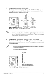
...; The FDD cable is removed to this connector. Floppy disk drive connector (34-1 pin FLOPPY) (for P7H55-M LE only) This connector is set the item to this connector, set to PIN 1. P7H55-M LE Floppy disk drive connector ASUS P7H55-M LE Series 1-14 7. If you want to connect an AC97 front panel audio module to this connector, ensure...
...; The FDD cable is removed to this connector. Floppy disk drive connector (34-1 pin FLOPPY) (for P7H55-M LE only) This connector is set the item to this connector, set to PIN 1. P7H55-M LE Floppy disk drive connector ASUS P7H55-M LE Series 1-14 7. If you want to connect an AC97 front panel audio module to this connector, ensure...
User Manual
Page 25
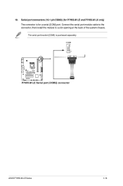
COM2 P7H55-M LE P7H55-M LE Serial port (COM2) connector ASUS P7H55-M LE Series 1-16 PIN 1 10. Connect the serial port module cable to the connector, then install the module to a slot opening at the back of the system chassis. Serial port connectors (10-1 pin COM2) (for P7H55-M LE and P7H55-M LX only) The connector is purchased separately. The serial port bracket (COM2) is for a serial (COM) port.
COM2 P7H55-M LE P7H55-M LE Serial port (COM2) connector ASUS P7H55-M LE Series 1-16 PIN 1 10. Connect the serial port module cable to the connector, then install the module to a slot opening at the back of the system chassis. Serial port connectors (10-1 pin COM2) (for P7H55-M LE and P7H55-M LX only) The connector is purchased separately. The serial port bracket (COM2) is for a serial (COM) port.

User Manual
Page 27
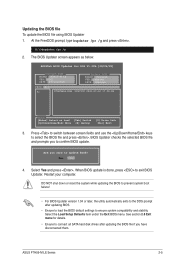
... BIOS file to a USB flash disk in the future. Click the Utilities tab, then click ASUS Update. 3. Select Update BIOS from the Internet a. ASUS P7H55-M LE Series 2-1 b. Copy the original motherboard BIOS using this utility. Installing ASUS Update To install ASUS Update: 1. Place the support DVD into the optical drive. From the Windows® desktop, click...
... BIOS file to a USB flash disk in the future. Click the Utilities tab, then click ASUS Update. 3. Select Update BIOS from the Internet a. ASUS P7H55-M LE Series 2-1 b. Copy the original motherboard BIOS using this utility. Installing ASUS Update To install ASUS Update: 1. Place the support DVD into the optical drive. From the Windows® desktop, click...
User Manual
Page 29
...partition only. • DO NOT shut down or reset the system while updating the BIOS to prevent system boot failure! 2.1.3 ASUS BIOS Updater The ASUS BIOS Updater allows you can use as shown. Boot your computer. The succeeding utility screens are for reference only. Booting the ...flash drive in DOS environment 1. Turn off the computer and disconnect all SATA hard disk drives (optional). When the ASUS Logo appears, press to boot using defaults ASUS P7H55-M LE Series 2-3 Insert the support DVD into the optical drive and select the optical drive as the boot device. Please ...
...partition only. • DO NOT shut down or reset the system while updating the BIOS to prevent system boot failure! 2.1.3 ASUS BIOS Updater The ASUS BIOS Updater allows you can use as shown. Boot your computer. The succeeding utility screens are for reference only. Booting the ...flash drive in DOS environment 1. Turn off the computer and disconnect all SATA hard disk drives (optional). When the ASUS Logo appears, press to boot using defaults ASUS P7H55-M LE Series 2-3 Insert the support DVD into the optical drive and select the optical drive as the boot device. Please ...
User Manual
Page 31
... bupdater /pc /g and press . When BIOS update is done, press to select the BIOS file and press . ASUS P7H55-M LE Series 2-5 D:\>bupdater /pc /g 2. See section 2.8 Exit menu for DOS V1.00b [09/06/22] Current ROM BOARD: P7H55-M LX VER: 0301 DATE: 07/12/2010 Update ROM BOARD: Unknown VER: Unknown DATE: Unknown PATH...
... bupdater /pc /g and press . When BIOS update is done, press to select the BIOS file and press . ASUS P7H55-M LE Series 2-5 D:\>bupdater /pc /g 2. See section 2.8 Exit menu for DOS V1.00b [09/06/22] Current ROM BOARD: P7H55-M LX VER: 0301 DATE: 07/12/2010 Update ROM BOARD: Unknown VER: Unknown DATE: Unknown PATH...
User Manual
Page 33
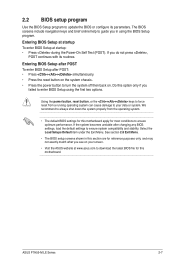
...; The default BIOS settings for this option only if you in this motherboard. Entering BIOS Setup at startup To enter BIOS Setup at www.asus.com to download the latest BIOS file for this section are for most conditions to ensure optimum performance. See section 2.8 Exit Menu. •... exactly match what you do not press , POST continues with its parameters. Select the Load Setups Default item under the Exit Menu. ASUS P7H55-M LE Series 2-7 We recommend to always shut down the system properly from a running operating system can cause damage to your screen. • Visit ...
...; The default BIOS settings for this option only if you in this motherboard. Entering BIOS Setup at startup To enter BIOS Setup at www.asus.com to download the latest BIOS file for this section are for most conditions to ensure optimum performance. See section 2.8 Exit Menu. •... exactly match what you do not press , POST continues with its parameters. Select the Load Setups Default item under the Exit Menu. ASUS P7H55-M LE Series 2-7 We recommend to always shut down the system properly from a running operating system can cause damage to your screen. • Visit ...
User Manual
Page 35
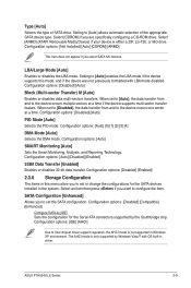
... Technology. SATA Configuration [Enhanced] Allows you to set or change the configurations for the Serial ATA connectors supported by Windows Vista/7 with LBA mode disabled. ASUS P7H55-M LE Series 2-9 Configuration options: [Not Installed] [Auto] [CDROM] [ARMD] This item does not appear if you are specifically configuring a CD-ROM drive. Configuration options: [Disabled] [Compatible...
... Technology. SATA Configuration [Enhanced] Allows you to set or change the configurations for the Serial ATA connectors supported by Windows Vista/7 with LBA mode disabled. ASUS P7H55-M LE Series 2-9 Configuration options: [Not Installed] [Auto] [CDROM] [ARMD] This item does not appear if you are specifically configuring a CD-ROM drive. Configuration options: [Disabled] [Compatible...
User Manual
Page 37
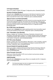
... system can function as well. Configuration options: [Disabled] [Enabled] Active Processor Cores [All] Allows you to enable or disable the No-Execution Page Protection Technology. ASUS P7H55-M LE Series 2-11 Configuration options: [All] [1] [2] A20M [Disabled] Setting this item to [Enabled] allows Legacy OSes to be required in independent partitions. Virtualization enhanced by making...
... system can function as well. Configuration options: [Disabled] [Enabled] Active Processor Cores [All] Allows you to enable or disable the No-Execution Page Protection Technology. ASUS P7H55-M LE Series 2-11 Configuration options: [All] [1] [2] A20M [Disabled] Setting this item to [Enabled] allows Legacy OSes to be required in independent partitions. Virtualization enhanced by making...

User Manual
Page 39
... enable or disable the onboard LAN controller. Configuration options: [Disabled] [Enabled] This item appears only on P7H55-M LE. Configuration options: [Disabled] [3F8/IRQ4] [2F8/IRQ3] [3E8/IRQ4] [2E8/IRQ3] The following items appear only on P7H55-M LE. Serial Port2 Address [2F8/IRQ3] Allows you to set to select parallel port IRQ. Configuration options: [Normal... you to [ECP] or [EPP+ECP]. Configuration options: [1.9] [1.7] Parallel Port IRQ [IRQ7] Allows you to select the Serial Port2 base address. Configuration options: [IRQ5] [IRQ7] ASUS P7H55-M LE Series 2-13
... enable or disable the onboard LAN controller. Configuration options: [Disabled] [Enabled] This item appears only on P7H55-M LE. Configuration options: [Disabled] [3F8/IRQ4] [2F8/IRQ3] [3E8/IRQ4] [2E8/IRQ3] The following items appear only on P7H55-M LE. Serial Port2 Address [2F8/IRQ3] Allows you to set to select parallel port IRQ. Configuration options: [Normal... you to [ECP] or [EPP+ECP]. Configuration options: [1.9] [1.7] Parallel Port IRQ [IRQ7] Allows you to select the Serial Port2 base address. Configuration options: [IRQ5] [IRQ7] ASUS P7H55-M LE Series 2-13
User Manual
Page 41
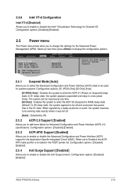
... enter the ACPI S3 (Suspend to enable or disable the Advanced Configuration and Power Interface (ACPI) support in the S1 state. Configuration options: [Disabled] [Enabled] ASUS P7H55-M LE Series 2-15 In S1 sleep state, the system appears suspended and stays in the RSDT pointer list. Main Advanced Power BIOS SETUP UTILITY Boot Tools...
... enter the ACPI S3 (Suspend to enable or disable the Advanced Configuration and Power Interface (ACPI) support in the S1 state. Configuration options: [Disabled] [Enabled] ASUS P7H55-M LE Series 2-15 In S1 sleep state, the system appears suspended and stays in the RSDT pointer list. Main Advanced Power BIOS SETUP UTILITY Boot Tools...
User Manual
Page 43
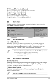
ASUS P7H55-M LE Series 2-17 Configuration options: [Disabled] [Enabled] CPU/Chassis Q-Fan Mode [Optimal] Allows ...function. Configuration options: [1st FLOPPY DRIVE] (for P7H55-M LE) / [Removable Dev.] (for P7H55-M LX) [Hard Drive] [ATAPI CD-ROM] [Disabled] • To select the boot device suring system startup, press when ASUS Logo appears. • To access Windows® OS...boot device priority sequence from the available devices. Select an item then press to use the ASUS MyLogo2™ feature. The number of device items that appears on the screen depends on the number of the...
ASUS P7H55-M LE Series 2-17 Configuration options: [Disabled] [Enabled] CPU/Chassis Q-Fan Mode [Optimal] Allows ...function. Configuration options: [1st FLOPPY DRIVE] (for P7H55-M LE) / [Removable Dev.] (for P7H55-M LX) [Hard Drive] [ATAPI CD-ROM] [Disabled] • To select the boot device suring system startup, press when ASUS Logo appears. • To access Windows® OS...boot device priority sequence from the available devices. Select an item then press to use the ASUS MyLogo2™ feature. The number of device items that appears on the screen depends on the number of the...
User Manual
Page 45
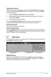
... and press . 2. To change the user password. Select an item then press to select andd update BIOS. CD-DISC (read only) 3. ASUS P7H55-M LE Series 2-19 Change User Password Select this item to clear the user password. Clear User Password Select this item to set to [Always], BIOS ...checks for special functions. NTFS (read only) ASUS EZ Flash 2 Allows you press , a confirmation message appears. FAT 12/16/32 (R/W) 2. After you set a password, this item shows Installed. On...
... and press . 2. To change the user password. Select an item then press to select andd update BIOS. CD-DISC (read only) 3. ASUS P7H55-M LE Series 2-19 Change User Password Select this item to clear the user password. Clear User Password Select this item to set to [Always], BIOS ...checks for special functions. NTFS (read only) ASUS EZ Flash 2 Allows you press , a confirmation message appears. FAT 12/16/32 (R/W) 2. After you set a password, this item shows Installed. On...
User Manual
Page 47
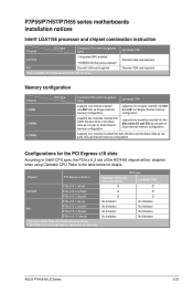
... slots as two pairs of the PCIe x16_2 slot varies by model. ** The PCIe x16_2 slot can work at maximum x8 link only. P7P55/P7H57/P7H55 series motherboards installation notices Intel® LGA1156 processor and chipset combination instruction Chipset CPU type Clarkdale CPU (with integrated GPU) H57/H55 • Integrated GPU... CPU type Clarkdale CPU (with integrated GPU) Lynnfield CPU O O X O O O No limitation No limitation No limitation No limitation No limitation No limitation No limitation No limitation ASUS P7H55-M LE Series 2-21
... slots as two pairs of the PCIe x16_2 slot varies by model. ** The PCIe x16_2 slot can work at maximum x8 link only. P7P55/P7H57/P7H55 series motherboards installation notices Intel® LGA1156 processor and chipset combination instruction Chipset CPU type Clarkdale CPU (with integrated GPU) H57/H55 • Integrated GPU... CPU type Clarkdale CPU (with integrated GPU) Lynnfield CPU O O X O O O No limitation No limitation No limitation No limitation No limitation No limitation No limitation No limitation ASUS P7H55-M LE Series 2-21


