
User Manual
Page 4
... Express x16 slot (x16 link 2-19 2.5.7 PCI Express x1 slot 2-19 2.5.8 PCI slots 2-19 2.5.9 Connect thermal sensor cable 2-20 2.5.10 Installing the audio card 2-20 2.6 Jumpers 2-21 2.7 Connectors 2-25 2.7.1 Rear panel connectors 2-25 2.7.2 ... shut down function 3-4 3.2.2 Using the dual function power switch 3-4 Chapter 4: BIOS setup 4.1 Managing and updating your BIOS 4-3 4.1.1 ASUS EZ Flash 2 utility 4-3 4.1.2 BUPDATER utility 4-4 4.1.3 ASUS CrashFree BIOS 3 utility 4-6 4.2 BIOS setup program 4-7 4.2.1 BIOS menu screen 4-8 4.2.2 Menu bar 4-8 4.2.3 Navigation keys 4-8 4.2.4...
... Express x16 slot (x16 link 2-19 2.5.7 PCI Express x1 slot 2-19 2.5.8 PCI slots 2-19 2.5.9 Connect thermal sensor cable 2-20 2.5.10 Installing the audio card 2-20 2.6 Jumpers 2-21 2.7 Connectors 2-25 2.7.1 Rear panel connectors 2-25 2.7.2 ... shut down function 3-4 3.2.2 Using the dual function power switch 3-4 Chapter 4: BIOS setup 4.1 Managing and updating your BIOS 4-3 4.1.1 ASUS EZ Flash 2 utility 4-3 4.1.2 BUPDATER utility 4-4 4.1.3 ASUS CrashFree BIOS 3 utility 4-6 4.2 BIOS setup program 4-7 4.2.1 BIOS menu screen 4-8 4.2.2 Menu bar 4-8 4.2.3 Navigation keys 4-8 4.2.4...

User Manual
Page 7
... • This device must accept any interference received including interference that interference will not occur in our products at ASUS REACH website at http://green.asus.com/english/REACH.htm. Operation is connected. • Consult the dealer or an experienced radio/TV technician for ...help. These limits are designed to assure compliance with manufacturer' s instructions, may cause undesired operation. The use of shielded cables for connection ...
... • This device must accept any interference received including interference that interference will not occur in our products at ASUS REACH website at http://green.asus.com/english/REACH.htm. Operation is connected. • Consult the dealer or an experienced radio/TV technician for ...help. These limits are designed to assure compliance with manufacturer' s instructions, may cause undesired operation. The use of shielded cables for connection ...

User Manual
Page 8
...with the package. • Before using an adapter or extension cord. Check local regulations for the devices are unplugged before the signal cables are using, contact your local power company. • If the power supply is set to fix it , carefully read all ...motherboard and adding devices on a stable surface. • If you are connected. If you add a device. • Before connecting or removing signal cables from connectors, slots, sockets and circuitry. • Avoid dust, humidity, and temperature extremes. Contact a qualified service technician or your dealer immediately. &#...
...with the package. • Before using an adapter or extension cord. Check local regulations for the devices are unplugged before the signal cables are using, contact your local power company. • If the power supply is set to fix it , carefully read all ...motherboard and adding devices on a stable surface. • If you are connected. If you add a device. • Before connecting or removing signal cables from connectors, slots, sockets and circuitry. • Avoid dust, humidity, and temperature extremes. Contact a qualified service technician or your dealer immediately. &#...

User Manual
Page 15
...above items is damaged or missing, contact your retailer. Optional items ASUS MIO audio card Description Discrete 8 channel audio card provides clearest high quality sounds ASUS P7F-X Series 1-3 Before you for LGA1156 (1U) 1 Application CD ...ASUS quality motherboards! Thank you start installing the motherboard, and hardware devices on it another standout in your package with the list below. 1.2 Package contents Check your motherboard package for the following items. Standard Gift Box Pack Cables SATA data cable 6 Accessories IO shield 1 Plate for buying an ASUS® P7F...
...above items is damaged or missing, contact your retailer. Optional items ASUS MIO audio card Description Discrete 8 channel audio card provides clearest high quality sounds ASUS P7F-X Series 1-3 Before you for LGA1156 (1U) 1 Application CD ...ASUS quality motherboards! Thank you start installing the motherboard, and hardware devices on it another standout in your package with the list below. 1.2 Package contents Check your motherboard package for the following items. Standard Gift Box Pack Cables SATA data cable 6 Accessories IO shield 1 Plate for buying an ASUS® P7F...

User Manual
Page 17
... SpeedStep Technology (EIST) intelligently manages the CPU resources by automatically adjusting the CPU voltage and core frequency depending on USB 2.0. ASUS P7F-X Series 1-5 PCIe 2.0 This motherboard supports the latest PCIe 2.0 device for DDR3. This enhances system performance while still providing backward...the current Serial ATA products with lower pin count and reduced voltage requirements. Serial ATA allows thinner, more flexible cables with a host of server and workstation applications. Marvell 88E8056 LAN Solution The motherboard comes with dual Gigabit LAN controllers...
... SpeedStep Technology (EIST) intelligently manages the CPU resources by automatically adjusting the CPU voltage and core frequency depending on USB 2.0. ASUS P7F-X Series 1-5 PCIe 2.0 This motherboard supports the latest PCIe 2.0 device for DDR3. This enhances system performance while still providing backward...the current Serial ATA products with lower pin count and reduced voltage requirements. Serial ATA allows thinner, more flexible cables with a host of server and workstation applications. Marvell 88E8056 LAN Solution The motherboard comes with dual Gigabit LAN controllers...

User Manual
Page 21
... the power supply is switched off mode. The green LED lights up to indicate that you should shut down the system and unplug the power cable before handling components to avoid damaging them . • Whenever you uninstall any motherboard component. This is a reminder that the system is detached from the wall... to static electricity. • Hold components by the edges to the motherboard, peripherals, and/or components. 2.1 Before you proceed Take note of the onboard LED ASUS P7F-X Series 2-3
... the power supply is switched off mode. The green LED lights up to indicate that you should shut down the system and unplug the power cable before handling components to avoid damaging them . • Whenever you uninstall any motherboard component. This is a reminder that the system is detached from the wall... to static electricity. • Hold components by the edges to the motherboard, peripherals, and/or components. 2.1 Before you proceed Take note of the onboard LED ASUS P7F-X Series 2-3

User Manual
Page 26
... panel connector (20-2 pin AUX_PANEL1) Page 2-26 2-27 2-27 2-28 2-28 2-29 2-29 2-30 2-30 2-31 2-32 2-33 2-8 Chapter 2: Hardware information Black) 2. Red) (P7F-X/SATA model only) 3. Thermal sensor cable connectors (3-pin TR1) 6. CPU, front and rear fan connectors (4-pin CPU_FAN1, FRNT_FAN1, FRNT_FAN2, FRNT_FAN3, REAR_FAN1) 7. A-Type USB7) 5. Serial General Purpose Input/Output connector...
... panel connector (20-2 pin AUX_PANEL1) Page 2-26 2-27 2-27 2-28 2-28 2-29 2-29 2-30 2-30 2-31 2-32 2-33 2-8 Chapter 2: Hardware information Black) 2. Red) (P7F-X/SATA model only) 3. Thermal sensor cable connectors (3-pin TR1) 6. CPU, front and rear fan connectors (4-pin CPU_FAN1, FRNT_FAN1, FRNT_FAN2, FRNT_FAN3, REAR_FAN1) 7. A-Type USB7) 5. Serial General Purpose Input/Output connector...

User Manual
Page 30
... the heatsink and fan assembly such that the four fasteners match the holes on top of the installed CPU, making sure that the CPU fan cable is incompatible with the LGA775 and LGA1366 sockets in a push-pin design and requires no tool to the CPU fan connector. 2-12 Chapter 2: Hardware information...
... the heatsink and fan assembly such that the four fasteners match the holes on top of the installed CPU, making sure that the CPU fan cable is incompatible with the LGA775 and LGA1366 sockets in a push-pin design and requires no tool to the CPU fan connector. 2-12 Chapter 2: Hardware information...

User Manual
Page 31
.... Pull up two fasteners at a time in a diagonal sequence to connect the CPU fan connector! ASUS P7F-X Series 2-13 Hardware monitoring errors can occur if you fail to the connector on the motherboard. 2. 3. Connect the CPU fan cable to plug this connector. 2.3.3 Uninstalling the CPU heatsink and fan To uninstall the CPU heatsink...
.... Pull up two fasteners at a time in a diagonal sequence to connect the CPU fan connector! ASUS P7F-X Series 2-13 Hardware monitoring errors can occur if you fail to the connector on the motherboard. 2. 3. Connect the CPU fan cable to plug this connector. 2.3.3 Uninstalling the CPU heatsink and fan To uninstall the CPU heatsink...

User Manual
Page 38
... connector on the slot completely. This slot does not support PCI-E x1 cards. 2-20 Chapter 2: Hardware information Place the other end of the thermal sensor cable to the device you would like to the connector. 3. Locate the audio slot on your motherboard. 1. Connect the thermal sensor...
... connector on the slot completely. This slot does not support PCI-E x1 cards. 2-20 Chapter 2: Hardware information Place the other end of the thermal sensor cable to the device you would like to the connector. 3. Locate the audio slot on your motherboard. 1. Connect the thermal sensor...

User Manual
Page 44
..., SATA6; Serial ATA connectors (7-pin SATA1, SATA2, SATA3, SATA4; Black) Supported by the Intel® 3420 chipset, these connectors are for the Serial ATA signal cables for Serial ATA hard disk drives that allows up to 3Gb/s of Serial ATA hard disks installed. • The...
..., SATA6; Serial ATA connectors (7-pin SATA1, SATA2, SATA3, SATA4; Black) Supported by the Intel® 3420 chipset, these connectors are for the Serial ATA signal cables for Serial ATA hard disk drives that allows up to 3Gb/s of Serial ATA hard disks installed. • The...

User Manual
Page 45
.../s of any device connected to the SATA or SAS add-on card causes the front panel LED to the SATA or SAS add-on card cable connected to light up. The read or write activities of data transfer rate. ASUS P7F-X Series 2-27 2. RED) (P7F-X/SATA model only) Supported by the Marvell®...; 88SE6145 chipset, these connectors are for the Serial ATA signal cables for the storage add...
.../s of any device connected to the SATA or SAS add-on card causes the front panel LED to the SATA or SAS add-on card cable connected to light up. The read or write activities of data transfer rate. ASUS P7F-X Series 2-27 2. RED) (P7F-X/SATA model only) Supported by the Marvell®...; 88SE6145 chipset, these connectors are for the Serial ATA signal cables for the storage add...

User Manual
Page 46
... to a slot opening at the back of the system chassis. USB connector (10-1 pin USB34, USB56; Thermal sensor cable connectors (3-pin TR1) This connector is for USB 2.0 ports. Connect the thermal sensor cable to this connector and place the other end to the device, which you want to monitor temperature. 2-28 Chapter...
... to a slot opening at the back of the system chassis. USB connector (10-1 pin USB34, USB56; Thermal sensor cable connectors (3-pin TR1) This connector is for USB 2.0 ports. Connect the thermal sensor cable to this connector and place the other end to the device, which you want to monitor temperature. 2-28 Chapter...

User Manual
Page 47
... ground pin of the system chassis. Connect the fan cables to the fan connectors on the fan connectors! • All fans feature the ASUS Smart Fan technology. 7. Insufficient air flow inside the system may damage the motherboard components. • These are not jumpers! ASUS P7F-X Series 2-29 CPU, front and rear fan connectors (4-pin...
... ground pin of the system chassis. Connect the fan cables to the fan connectors on the fan connectors! • All fans feature the ASUS Smart Fan technology. 7. Insufficient air flow inside the system may damage the motherboard components. • These are not jumpers! ASUS P7F-X Series 2-29 CPU, front and rear fan connectors (4-pin...

User Manual
Page 48
Serial General Purpose Input/Output connector (6-1 pin SGPIO1) This connector is for the Intel Matrix RAID SATA LED. 9. Serial port connector (10-1 pin COM2) This connector is used for the SGPIO peripherals for a serial (COM) port. Connect the serial port module cable to this connector, then install the module to a slot opening at the back of the system chassis. 2-30 Chapter 2: Hardware information 8.
Serial General Purpose Input/Output connector (6-1 pin SGPIO1) This connector is for the Intel Matrix RAID SATA LED. 9. Serial port connector (10-1 pin COM2) This connector is used for the SGPIO peripherals for a serial (COM) port. Connect the serial port module cable to this connector, then install the module to a slot opening at the back of the system chassis. 2-30 Chapter 2: Hardware information 8.

User Manual
Page 50
... LED (2-pin HDDLED) This 2-pin connector is for the HDD Activity LED. Message LED (2-pin MLED) This 2-pin connector is for the message LED cable that connects to this connector. The speaker allows you turn on the BIOS settings. Connect the HDD Activity LED...sleep mode. 2. Reset button (2-pin RESET) This 2-pin connector is read from or written to hear system beeps and warnings. 4. Connect the chassis power LED cable to indicate an abnormal event occurance. 3. Pressing the power switch for more than four seconds while the system is for system reboot without turning off...
... LED (2-pin HDDLED) This 2-pin connector is for the HDD Activity LED. Message LED (2-pin MLED) This 2-pin connector is for the message LED cable that connects to this connector. The speaker allows you turn on the BIOS settings. Connect the HDD Activity LED...sleep mode. 2. Reset button (2-pin RESET) This 2-pin connector is read from or written to hear system beeps and warnings. 4. Connect the chassis power LED cable to indicate an abnormal event occurance. 3. Pressing the power switch for more than four seconds while the system is for system reboot without turning off...

User Manual
Page 51
... button on the front panel. Locator Button/Swich (2-pin LOCATORBTN) These leads are for Gigabit LAN activity LEDs on the front panel. ASUS P7F-X Series 2-33 Auxiliary panel connector (20-pin AUX_PANEL1) This connector is pressed. 5. Chassis intrusion (4-1 pin CHASSIS) These leads are ... button is for chassis with intrusion sensor or microswitch. Connect the Locator LED cables to record a chassis intrusion event. Front panel SMB (6-1 pin FPSMB) These leads connect the front panel SMBus cable. 2. When you remove any chassis component, the sensor triggers and sends a...
... button on the front panel. Locator Button/Swich (2-pin LOCATORBTN) These leads are for Gigabit LAN activity LEDs on the front panel. ASUS P7F-X Series 2-33 Auxiliary panel connector (20-pin AUX_PANEL1) This connector is pressed. 5. Chassis intrusion (4-1 pin CHASSIS) These leads are ... button is for chassis with intrusion sensor or microswitch. Connect the Locator LED cables to record a chassis intrusion event. Front panel SMB (6-1 pin FPSMB) These leads connect the front panel SMBus cable. 2. When you remove any chassis component, the sensor triggers and sends a...
User Manual
Page 100
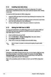
... for RAID set using the utilities embedded in each RAID controller. Set Configure SATA as to the SATA connector on the RAID connectors that you use the RAID configuration utility. 5-4 Chapter 5: RAID configuration Connect a SATA signal cable to the signal connector at the back of the same model and capacity when... in the BIOS Setup before you installed Serial ATA hard disk drives on how to save your changes and exit the BIOS Setup. Connect a SATA power cable to the power connector on each drive and to [RAID] 4. Enter the BIOS Setup during POST. 2. Go to the Main Menu > ...
... for RAID set using the utilities embedded in each RAID controller. Set Configure SATA as to the SATA connector on the RAID connectors that you use the RAID configuration utility. 5-4 Chapter 5: RAID configuration Connect a SATA signal cable to the signal connector at the back of the same model and capacity when... in the BIOS Setup before you installed Serial ATA hard disk drives on how to save your changes and exit the BIOS Setup. Connect a SATA power cable to the power connector on each drive and to [RAID] 4. Enter the BIOS Setup during POST. 2. Go to the Main Menu > ...