
User Guide
Page 1
Motherboard P7F-C Series P7F-C/SAS P7F-C/4L
Motherboard P7F-C Series P7F-C/SAS P7F-C/4L

User Guide
Page 3
Contents Notices...vii Safety information viii About this guide ix Typography x P7F-C Series specifications summary xi Chapter 1: Product introduction 1.1 Welcome 1-3 1.2 Package contents 1-3 1.3 Serial number label 1-4 1.4 Special features 1-4 1.4.1 Product highlights 1-4 Chapter 2: Hardware information 2.1 Before you proceed 2-3 2.2 Motherboard overview 2-4 2.2.1 Placement direction 2-4 2.2.2 Screw holes 2-4 2.2.3 Motherboard layout 2-5 2.2.4 Layout contents 2-7 2.3 Central Processing Unit (CPU 2-9 2.3.1 Installing the CPU 2-9 2.3.2 Installing the...
Contents Notices...vii Safety information viii About this guide ix Typography x P7F-C Series specifications summary xi Chapter 1: Product introduction 1.1 Welcome 1-3 1.2 Package contents 1-3 1.3 Serial number label 1-4 1.4 Special features 1-4 1.4.1 Product highlights 1-4 Chapter 2: Hardware information 2.1 Before you proceed 2-3 2.2 Motherboard overview 2-4 2.2.1 Placement direction 2-4 2.2.2 Screw holes 2-4 2.2.3 Motherboard layout 2-5 2.2.4 Layout contents 2-7 2.3 Central Processing Unit (CPU 2-9 2.3.1 Installing the CPU 2-9 2.3.2 Installing the...

User Guide
Page 8
...not sure about the voltage of the electrical outlet you add a device. • Before connecting or removing signal cables from the motherboard, ensure that all cables are correctly connected and the power cables are connected. Safety information Electrical safety • To prevent electrical shock...all power cables are unplugged. • Seek professional assistance before the signal cables are not damaged. Operation safety • Before installing the motherboard and adding devices on a stable surface. • If you detect any damage, contact your local power company. • If the...
...not sure about the voltage of the electrical outlet you add a device. • Before connecting or removing signal cables from the motherboard, ensure that all cables are correctly connected and the power cables are connected. Safety information Electrical safety • To prevent electrical shock...all power cables are unplugged. • Seek professional assistance before the signal cables are not damaged. Operation safety • Before installing the motherboard and adding devices on a stable surface. • If you detect any damage, contact your local power company. • If the...
User Guide
Page 9
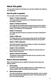
... descriptions of the BIOS parameters are not part of the switches, jumpers, and connectors on ASUS hardware and software products. ASUS websites The ASUS website provides updated information on the motherboard. • Chapter 3: Powering up This chapter describes the power up , creating, and configuring... as warranty flyers, that may refer to the ASUS contact information. 2. These documents are also provided. • Chapter 5: RAID configuration This chapter provides instructions for setting up sequence and ways of the motherboard and the new technologies it supports. • ...
... descriptions of the BIOS parameters are not part of the switches, jumpers, and connectors on ASUS hardware and software products. ASUS websites The ASUS website provides updated information on the motherboard. • Chapter 3: Powering up This chapter describes the power up , creating, and configuring... as warranty flyers, that may refer to the ASUS contact information. 2. These documents are also provided. • Chapter 5: RAID configuration This chapter provides instructions for setting up sequence and ways of the motherboard and the new technologies it supports. • ...

User Guide
Page 13
This chapter describes the motherboard introPdruoc1dtuiocnt features and the new technologies it supports.
This chapter describes the motherboard introPdruoc1dtuiocnt features and the new technologies it supports.

User Guide
Page 15
... LGA1156 (1U) 1 Application CD Support CD 1 Documentation User Guide 1 Packing Qty. 1pc per carton Standard Bulk Pack -1 1 1 1 10pcs per carton If any of ASUS quality motherboards! ASUS P7F-C Series 1-3 Thank you start installing the motherboard, and hardware devices on it another standout in your package with the list below. 1.2 Package contents Check your retailer. The...
... LGA1156 (1U) 1 Application CD Support CD 1 Documentation User Guide 1 Packing Qty. 1pc per carton Standard Bulk Pack -1 1 1 1 10pcs per carton If any of ASUS quality motherboards! ASUS P7F-C Series 1-3 Thank you start installing the motherboard, and hardware devices on it another standout in your package with the list below. 1.2 Package contents Check your retailer. The...

User Guide
Page 16
...level parallelism on today's multi-threaded software. 1.3 Serial number label Before requesting support from the ASUS Technical Support team, you must take note of the motherboard's serial number containing 13 characters xxS2xxxxxxxxx shown as the figure below power, temperature and current ... workloads. The Intel® EM64T feature allows your problems. P7F-C Series xxS2xxxxxxxxx Made in China 合格 1.4 Special features 1.4.1 Product highlights Intel® LGA1156 Xeon 3400 Processor Ready This motherboard supports the latest Intel® Xeon 3400 processors in the ...
...level parallelism on today's multi-threaded software. 1.3 Serial number label Before requesting support from the ASUS Technical Support team, you must take note of the motherboard's serial number containing 13 characters xxS2xxxxxxxxx shown as the figure below power, temperature and current ... workloads. The Intel® EM64T feature allows your problems. P7F-C Series xxS2xxxxxxxxx Made in China 合格 1.4 Special features 1.4.1 Product highlights Intel® LGA1156 Xeon 3400 Processor Ready This motherboard supports the latest Intel® Xeon 3400 processors in the ...
User Guide
Page 17
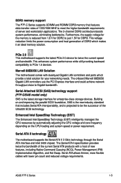
.... The 2-channel DDR3 architecture boosts system performance, eliminating bottlenecks. PCIe 2.0 This motherboard supports the latest PCIe 2.0 device for enterprise-class storage devices. DDR3 memory support The P7F-C Series supports UDIMM and RDIMM DDR3 memory that includes Serial ATA interoperability, and...which makes it an ideal memory solution. Marvell 88E8056 LAN Solution The motherboard comes with lower pin count and reduced voltage requirements. ASUS P7F-C Series 1-5 Serial Attached SCSI (SAS) technology support (P7F-C/SAS model only) SAS is reduced from 1.8 V for DDR2 ...
.... The 2-channel DDR3 architecture boosts system performance, eliminating bottlenecks. PCIe 2.0 This motherboard supports the latest PCIe 2.0 device for enterprise-class storage devices. DDR3 memory support The P7F-C Series supports UDIMM and RDIMM DDR3 memory that includes Serial ATA interoperability, and...which makes it an ideal memory solution. Marvell 88E8056 LAN Solution The motherboard comes with lower pin count and reduced voltage requirements. ASUS P7F-C Series 1-5 Serial Attached SCSI (SAS) technology support (P7F-C/SAS model only) SAS is reduced from 1.8 V for DDR2 ...

User Guide
Page 18
USB 2.0 is monitored to prevent overheating and damage. The chip monitors the voltage levels to a fast 480 Mbps on USB 2.0. The system fan rotations per minute (RPM) is monitored for critical components. 1-6 Chapter 1: Product introduction USB 2.0 technology The motherboard implements the Universal Serial Bus (USB) 2.0 specification, dramatically increasing the connection speed from the 12 Mbps bandwidth on USB 1.1 to ensure stable supply of current for timely failure detection. Temperature, fan, and voltage monitoring The CPU temperature is backward compatible with USB 1.1.
USB 2.0 is monitored to prevent overheating and damage. The chip monitors the voltage levels to a fast 480 Mbps on USB 2.0. The system fan rotations per minute (RPM) is monitored for critical components. 1-6 Chapter 1: Product introduction USB 2.0 technology The motherboard implements the Universal Serial Bus (USB) 2.0 specification, dramatically increasing the connection speed from the 12 Mbps bandwidth on USB 1.1 to ensure stable supply of current for timely failure detection. Temperature, fan, and voltage monitoring The CPU temperature is backward compatible with USB 1.1.

User Guide
Page 19
This chapter lists the hardware setup procedures that you have to perform when installing system components. It includes description of the jumpers and connectors on the motherboard. 2 Hardware information
This chapter lists the hardware setup procedures that you have to perform when installing system components. It includes description of the jumpers and connectors on the motherboard. 2 Hardware information

User Guide
Page 20
Chapter summary 2 2.1 Before you proceed 2-3 2.2 Motherboard overview 2-4 2.3 Central Processing Unit (CPU 2-9 2.4 System memory 2-15 2.5 Expansion slots 2-17 2.6 Jumpers 2-21 2.7 Connectors 2-25 ASUS P7F-C Series
Chapter summary 2 2.1 Before you proceed 2-3 2.2 Motherboard overview 2-4 2.3 Central Processing Unit (CPU 2-9 2.4 System memory 2-15 2.5 Expansion slots 2-17 2.6 Jumpers 2-21 2.7 Connectors 2-25 ASUS P7F-C Series

User Guide
Page 21
...system and unplug the power cable before handling components to avoid damaging them due to static electricity. • Hold components by the edges to the motherboard, peripherals, and/or components. This is detached from the wall socket before touching any component. • Use a grounded wrist strap or touch...in the bag that came with a standby power LED. The green LED lights up to indicate that the power supply is switched off mode. ASUS P7F-C Series 2-3 Failure to do so may cause severe damage to avoid touching the ICs on them. • Whenever you uninstall any component, ...
...system and unplug the power cable before handling components to avoid damaging them due to static electricity. • Hold components by the edges to the motherboard, peripherals, and/or components. This is detached from the wall socket before touching any component. • Use a grounded wrist strap or touch...in the bag that came with a standby power LED. The green LED lights up to indicate that the power supply is switched off mode. ASUS P7F-C Series 2-3 Failure to do so may cause severe damage to avoid touching the ICs on them. • Whenever you uninstall any component, ...

User Guide
Page 22
... that you install it in the image below. 2.2.2 Screw holes Place nine (9) screws into the holes indicated by circles to secure the motherboard to the chassis. The edge with external ports goes to the rear part of the chassis as indicated in an ATX 1.1 compliant chassis.... Failure to do so can damage the motherboard. DO NOT overtighten the screws! Place this side towards the rear of the chassis 2-4 Chapter 2: Hardware information 2.2 Motherboard overview Before you install the motherboard, study the configuration of your chassis to ensure that you place ...
... that you install it in the image below. 2.2.2 Screw holes Place nine (9) screws into the holes indicated by circles to secure the motherboard to the chassis. The edge with external ports goes to the rear part of the chassis as indicated in an ATX 1.1 compliant chassis.... Failure to do so can damage the motherboard. DO NOT overtighten the screws! Place this side towards the rear of the chassis 2-4 Chapter 2: Hardware information 2.2 Motherboard overview Before you install the motherboard, study the configuration of your chassis to ensure that you place ...

User Guide
Page 23
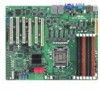
2.2.3 Motherboard layout P7F-C/SAS ASUS P7F-C Series 2-5
2.2.3 Motherboard layout P7F-C/SAS ASUS P7F-C Series 2-5

User Guide
Page 27
.... 2.3.1 Installing the CPU To install a CPU: 1. Press the load lever with the cap on the motherboard. ASUS will process Return Merchandise Authorization (RMA) requests only if the motherboard comes with your left. 2. To prevent damage to the socket contacts resulting from the retention tab. Locate... are not bent. ASUS will shoulder the cost of the motherboard, ensure that the socket box is facing toward you see any damage to the right (B) until it is on your thumb (A), and then move it to the PnP cap/socket contacts/motherboard components. ASUS P7F-C Series Load lever...
.... 2.3.1 Installing the CPU To install a CPU: 1. Press the load lever with the cap on the motherboard. ASUS will process Return Merchandise Authorization (RMA) requests only if the motherboard comes with your left. 2. To prevent damage to the socket contacts resulting from the retention tab. Locate... are not bent. ASUS will shoulder the cost of the motherboard, ensure that the socket box is facing toward you see any damage to the right (B) until it is on your thumb (A), and then move it to the PnP cap/socket contacts/motherboard components. ASUS P7F-C Series Load lever...

User Guide
Page 30
To install the CPU heatsink and fan: 1. If you install the heatsink and fan assembly. Place the heatsink on the motherboard. Push down two fasteners at a time in a diagonal sequence to install. • Use an LGA1156-compatible CPU heatsink and fan assembly only. B 2. A B A A B B A 1... in place. Ensure that the four fasteners match the holes on top of the installed CPU, making sure that you have installed the motherboard to the CPU heatsink or CPU before you use only Intel®‑certified multi‑directional heatsink and fan. • Your Intel...
To install the CPU heatsink and fan: 1. If you install the heatsink and fan assembly. Place the heatsink on the motherboard. Push down two fasteners at a time in a diagonal sequence to install. • Use an LGA1156-compatible CPU heatsink and fan assembly only. B 2. A B A A B B A 1... in place. Ensure that the four fasteners match the holes on top of the installed CPU, making sure that you have installed the motherboard to the CPU heatsink or CPU before you use only Intel®‑certified multi‑directional heatsink and fan. • Your Intel...

User Guide
Page 31
Hardware monitoring errors can occur if you fail to disengage the heatsink and fan assembly from the motherboard. Rotate each fastener counterclockwise. 3. Pull up two fasteners at a time in a diagonal sequence to plug this connector. 2.3.3 Uninstalling the CPU ... heatsink and fan: 1. Disconnect the CPU fan cable from the motherboard. Connect the CPU fan cable to connect the CPU fan connector! Carefully remove the heatsink and fan assembly from B the connector on the motherboard labeled CPU_FAN1. 3. ASUS P7F-C Series 2-13 DO NOT forget to the connector on the...
Hardware monitoring errors can occur if you fail to disengage the heatsink and fan assembly from the motherboard. Rotate each fastener counterclockwise. 3. Pull up two fasteners at a time in a diagonal sequence to plug this connector. 2.3.3 Uninstalling the CPU ... heatsink and fan: 1. Disconnect the CPU fan cable from the motherboard. Connect the CPU fan cable to connect the CPU fan connector! Carefully remove the heatsink and fan assembly from B the connector on the motherboard labeled CPU_FAN1. 3. ASUS P7F-C Series 2-13 DO NOT forget to the connector on the...

User Guide
Page 32
... or tilted, otherwise the CPU will overheat. 2-14 Chapter 2: Hardware information Ensure that you have applied the thermal interface material to the top of the motherboard, matching the standoffs to the heatsink screw holes. 2.
... or tilted, otherwise the CPU will overheat. 2-14 Chapter 2: Hardware information Ensure that you have applied the thermal interface material to the top of the motherboard, matching the standoffs to the heatsink screw holes. 2.

User Guide
Page 33
DDR3 modules are not supported ASUS P7F-C Series 2-15 For optimum compatibility, it is notched differently to prevent installation on a DDR2 DIMM socket. RDIMM* DIMM Slot DIMM Populated DIMM Type Per Channel ... Rank 2 2 Unbuffered DDR3 1333 Single Rank, Dual Rank *Support Low Voltage DIMMs; **Down from the same vendor. DO NOT combine RDIMM and UDIMM. • The motherboard supports x8 DRAM Only and x4 & x16 DRAM are developed for better performance with the same CAS latency. A DDR3 module has the same physical dimensions...
DDR3 modules are not supported ASUS P7F-C Series 2-15 For optimum compatibility, it is notched differently to prevent installation on a DDR2 DIMM socket. RDIMM* DIMM Slot DIMM Populated DIMM Type Per Channel ... Rank 2 2 Unbuffered DDR3 1333 Single Rank, Dual Rank *Support Low Voltage DIMMs; **Down from the same vendor. DO NOT combine RDIMM and UDIMM. • The motherboard supports x8 DRAM Only and x4 & x16 DRAM are developed for better performance with the same CAS latency. A DDR3 module has the same physical dimensions...

User Guide
Page 34
... it flips out with 1 1 your fingers when pressing the retaining clips. Align a DIMM on the socket. 3. Simultaneously press the retaining clips outward to both the motherboard and the components. DO NOT force a DIMM into the socket until the retaining clips snap back in only one direction. 2.4.3 Installing a DIMM Unplug the power...
... it flips out with 1 1 your fingers when pressing the retaining clips. Align a DIMM on the socket. 3. Simultaneously press the retaining clips outward to both the motherboard and the components. DO NOT force a DIMM into the socket until the retaining clips snap back in only one direction. 2.4.3 Installing a DIMM Unplug the power...

